 Anders Helgesson
The GreenPAK keypad scanning design with the new pinout looks like this.
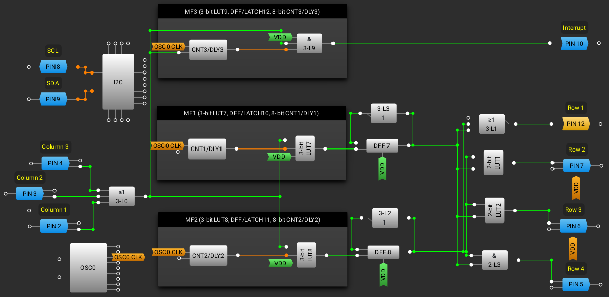
The columns share the same LUT and to keep it simple and just one I2C read to get the key pressed. I'm reading 3 bytes. Byte 0x74, Byte 0x75 and Byte 0x76. These contains the matrix inputs and LUT outputs used.
These are used to determine which key was pressed. Since I don't change the pinout often. I'm just going to update the code with the new pinout, it's just simpler. I updated the bitmask with the new setup for the column pins, for the rows I were reading the LUTs already so nothing have changed here. It now works again. I've flashed the new design onto the GreenPAK.
My erase command doesn't seem to properly erase the device. The new code and pinout works if I write directly to the registers.
If I use my NVRAM erase, flash and then reset the device it doesn't work. I'm guess my erase command does not erase all of the NVRAM properly. I have to go through and get the NVRAM erase to work properly. I have to write some debug features to read and compare the NVRAM and registers.
So it wasn't a problem with the schmitt triggers, so I put them back on the column inputs and tested it. It works perfectly and might even be more robust with the schmitt triggers on the column inputs.
Discussions
Become a Hackaday.io Member
Create an account to leave a comment. Already have an account? Log In.