 Anders Helgesson
To implement my H-Bridge gate driver in the GreenPAK I have to have a test circuit. I've decided to wire it up on a small breadboard.
A 5 Volt PSU will power the 40 Volt PSU and H-Bridge opto-coupler pull-ups. A load-switch will turn on a LED and is a stand in for the 40 Volt PSU. The will opto-couplers are connected to LED's as well. I will be using a pin as output for the fault and it will turn on a LED.
Here is the design for the gate-control in the GreenPAK.
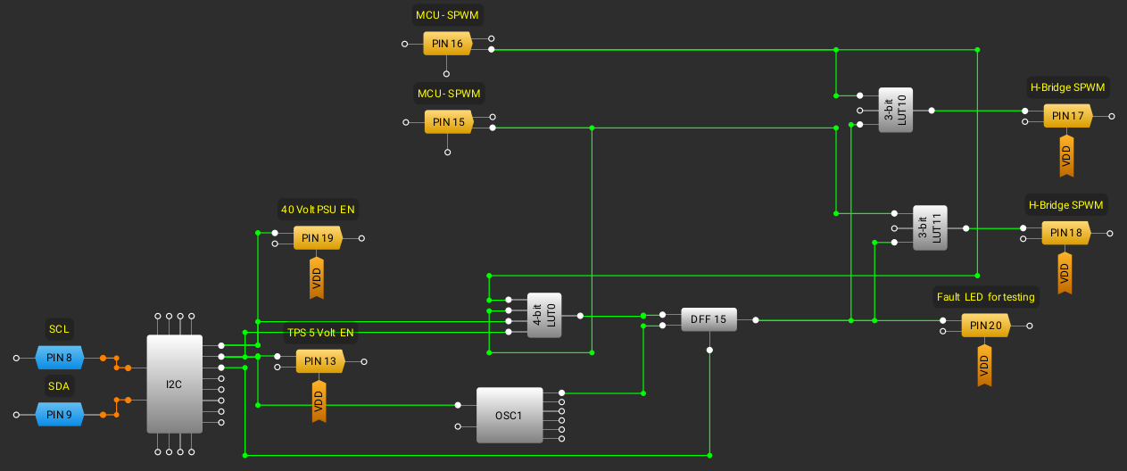
Here is how this should work. The 4-bit LUT checks the output signals, 5 Volt supply EN and 40 Volt PSU EN.
It outputs a 1 if both SPWM channels are on at the same time, it also checks that the 40Volt PSU has been turned on and that the 5 Volt supply is also on. The 40 Volt PSU can not be turned on before the 5 Volt PSU this will also register a fault.
It's latched by the DFF until reset by the MCU via one of the I2C virtual output registers.
The SPWM LUT's inverts the logic and if it has a fault signal locks both channels so they make sure that the H-Bridge is off.
The PSU's are also controlled by the MCU via the I2C virtual output registers.
Now to test this design I have to wire up the test board and do some programming.
I'm going to make used of the command mode of the phone. Fault reset command, would reset the DFF if a fault has occured. Bell ringer test command, when this command is activated and the handset placed back on, a timer starts and executes a simulated call by ringing the bells until the handset is picked up.
With a test circuit there is no risk of something blowing up, while implementing the new Bell Ringer control.
Discussions
Become a Hackaday.io Member
Create an account to leave a comment. Already have an account? Log In.