 Anders Helgesson
I've decided to skip the reading of the voltage from the 40 Volt PSU and use that pin as a fault output for the H-Bridge control. Now all the pins of the GreenPAK(SLG46826V) are in use. I'm now using a virtual input register in the GreenPAK to control the 40 Volt PSU and the MCU pin originally intended for this purpose has become the fault interrupt input.
I connected it all up and it looks like this. The added test circuit breadboard with the LED's and lots of wires.
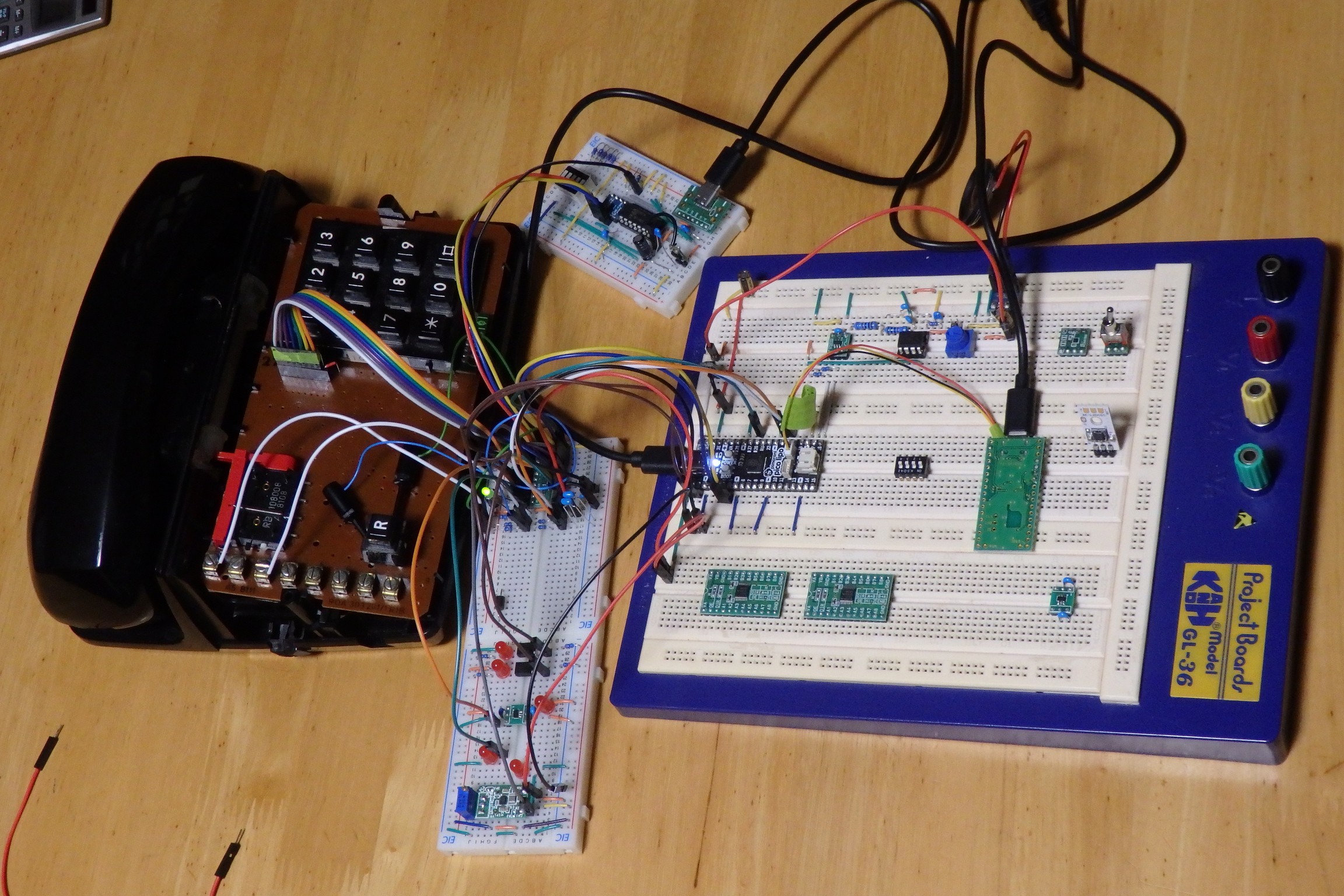
The TPS module is set at 5 volt to power the H-Bridge and 40V PSU.
Opto-couplers with 1k pulls ups are powered from the TPS module. They are controlled by the greenPAK.
The load switch will be a stand in for the 40V PSU with a LED.
Before I mentioned I would use a load switch for the H-bridge but since there is nothing to power there except for the pull ups, I've decided to use the EN pin on the TPS module instead. It's EN is sinked to ground by the GreenPAK to turn it off.
Here is what the H-Bridge gate driver GreenPAK design now looks like.
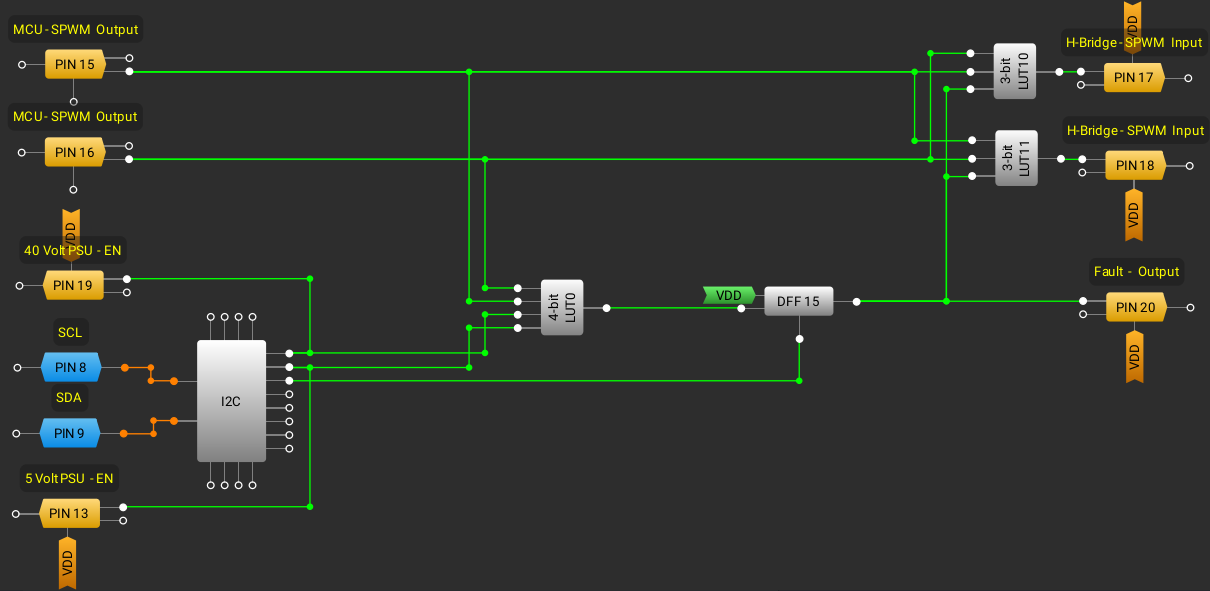
First the two 3-bit LUT's takes the MCU SPWM signals inverts the signals and outputs them to the H-Bridge gates. They also make sure that both signals can not be on at the same time. The fault signal is also sent taken into account as an extra safety, if a fault has been latched it can not drive the gates.
The 4-bit LUT takes both MCU SPWM signals, TPS EN signal and the 40 Volt PSU signal. This makes it not possible to drive the gates without the 40 Volt PSU on. A DFF is connected to the output and if it's HIGH it will latch until cleared using the I2C controlled register.
I noticed that the LED's I used have inbuilt resistors(for 5volts) on the positive side(anode), with the 1K pull up acts as a voltage divider. Using these kind of LED's for breadboarding should probably be avoided, when they make a voltage divider when you don't want one.
Programming the new functionality. I've decided to make a general read_virtual_input_register and write_virtual_input_register. So it's easy to use these registers, there is 8 in total.
I added the new simulate call state and some other code to make that work. I had to debug some code and fix some issues. Commands for resetting the fault condition and simulate a call have been added. I also added so I can access all the virtual input registers as well for testing.
At first it didn't work like it should and it was because I had configured the 4-bit LUT the wrong way. Since I used this test circuit and not the live H-Bridge, no magic smoke event occured. After I reconfigured the 4-Bit LUT it started working as it should.
I tested all the logic of the 4-Bit LUT and Injected 3.3 volts on each of the sPWM signals from the MCU to test the shoot-through protection. The H-Bridge gate driver works like it should and should protect the H-Bridge from blowing up.
Discussions
Become a Hackaday.io Member
Create an account to leave a comment. Already have an account? Log In.