 Anders Helgesson
It kept bugging me that I have no way of knowing if under-voltage occur for the 40 Volt PSU. I could just skip it but the whole reason I'm doing the project is for learning, so I started squeezing the last resources out of the greenPAK to see if I can make it happen.
Here is the new greenPAK design. I were able to get the check for over-voltage in there as well.
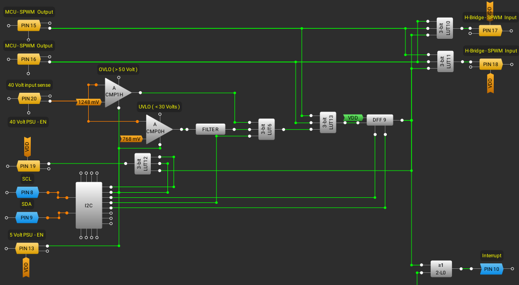
Like before it is not possible for both sPWM channels to be on at the same time. This would also latch the fault DFF. If a fault is latched the sPWM outputs can not drive the gates again until the fault is cleared.
Under or over voltage also latches a fault using the ACMP's to measure the voltage. Both ACMP's are powered by the same signal that enables the 5 Volt rail. The outputs of both ACMP's can be ignored using a I2C register. This is neccessary to not get a fault when turning on or off 40 Volt PSU. During power up/down the outputs will be filtered out using the LUT when the register is set.
The 5 volt EN signal is turned on, it also power the ACMP's, then turn on the 40 Volt PSU, check the UVLO ACMP that power has been established, then clear the acmp signal ignore and it should be ready for sPWM.
To free up the pin needed for the voltage sense, I made the fault interrupt share the keypad matrix interrupt pin. This also have to be addressed in programming by using I2C to check if it's a Fault that triggered it or not.
Using a macrocell with a DFF that has both nRESET and nSET for the fault latch. I can trigger a fault at anytime via the Virtual I2C register. It could be used for testing so I put it in there.
To test the ACMP's I will use a SMPS TPS module set at 4 volts and use a voltage divider to get 1 Volt output. Connect that through a 1k series resistor and have an 0.01uF cap for filtering. I can get the programming right before moving onto the real 40Volt supply and H-Bridge.
I need to order Schottsky diodes to protect the greenPAK input and some other components.
So what is the problem with this design?
Before I had a problem with the first byte of the SLG46826 register, I can not write to it. It controls the matrix outputs for the 2-Bit LUT0. Since I had enough resources I just simply switched to another LUT to get on with the project. Now I need to use that LUT again.
I have to troubleshoot this. I will first solder another SLG46826 module and test if its possible to write to the first byte, just to rule out a problem with the one I'm currently using. Then I have to go through the code for my greenPAK tool. I guess having the offical debug tool would make things easier but I'm learning a lot more this way.
Discussions
Become a Hackaday.io Member
Create an account to leave a comment. Already have an account? Log In.