 Anders Helgesson
I was a bit optimistic that I would get the lab up and running in 1 month... I'm still waiting for stuff to be cleared out of the room so I can use it. If the room was completely empty, it would be up and running by now. It's not in my hands right now, which kinda sucks. I've waited this long I can wait a bit longer.
Let's see where did I left off. I was getting the H-bridge gate driver design ready to ring the bells. I wanted to try to make a UVLO and OVLO by using the last remaining resources in the greenpak.
I've now decided that for the prototype to skip both of those. I'll have to resdesign everything in the end anyway. It's a prototype and if a magic smoke event happens it happens.
I get to see my long lost friend again. No offense but what a mess you are.
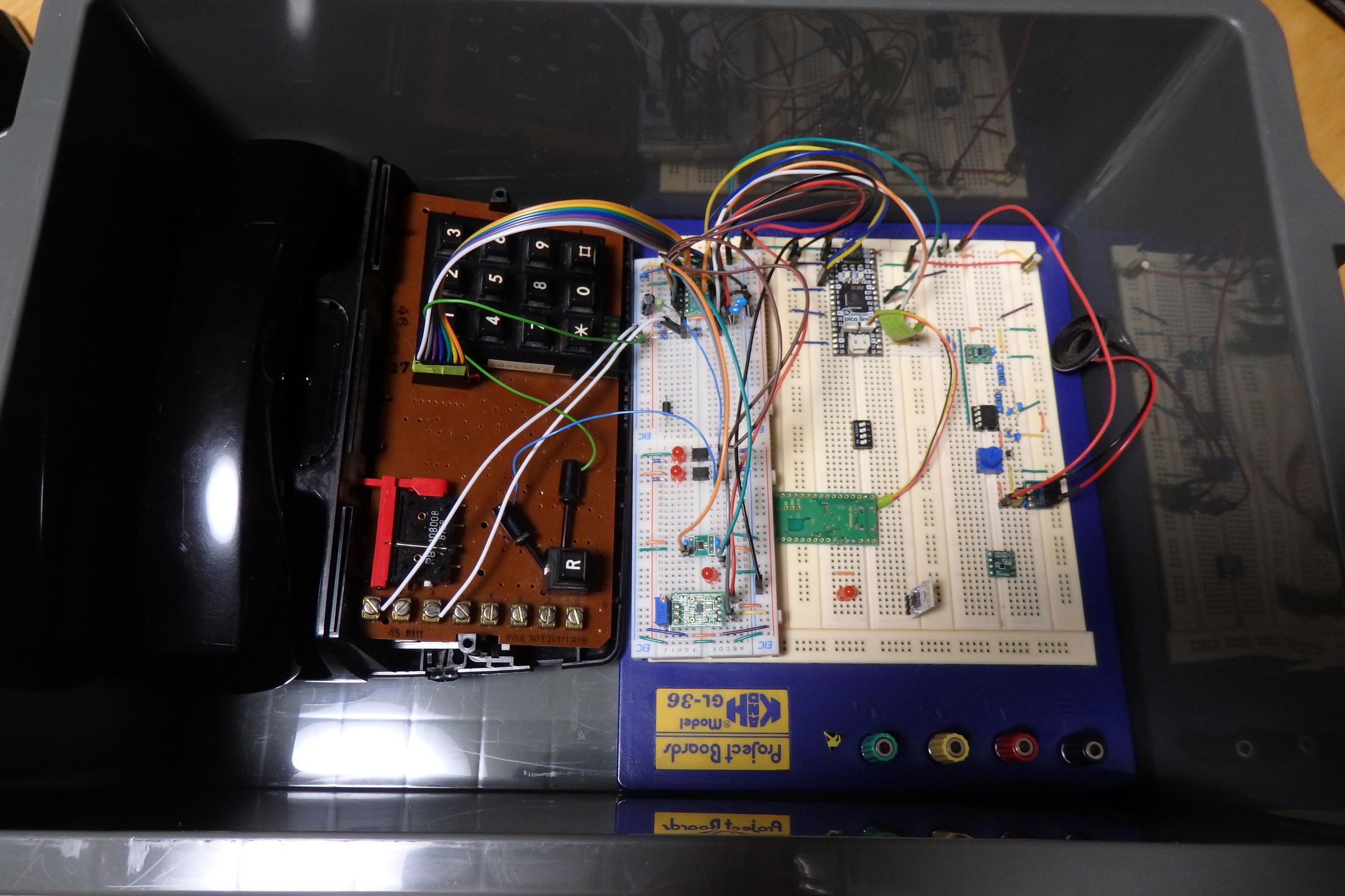
Since I'm just messing around with a purpose I have no schematic. Once I have the prototype working I will redesign it with a schematic. It should probably be done the other way around. :)
After some testing of the current programming I noticed some bugs which have to be fixed.
Bug 1:
If you simulate a call and pick up the handset while the bells are ringing it doesn't cut the bells ringing until after the DMA transfer has completed. If you pickup the handset when it's not activly ringing the bells it goes directly to idle state like it's programmed. I have to take a look at the DMA transfer why it's not cancelled when handset is picked up.
Bug 2:
There is no power on reset in my greenpak design so when I plug it into power it sends a pulse to all the gpio in the greenpak which makes the loadswitch turn on a for breif moment and both gate drivers. This might cause a shoot-through in the h-bridge.
Bug 3:
When you put on the handset while the no connection tone rings it doesn't cut it right away. This probably has to do with the DMA transfer and it's the same type of bug as Bug 1. But this time when the no connection tone is playing. Have to look at the tone playback code.
Bug 4:
When you answer the simulated call the psu is not turned off which means the 40 volt psu would still be powered. I need to take a look at the code handling the 40 volt and 5 Volt psu.
Other than I can not notice anything wrong. Keypad is very responsive and there is no fault when push the keys in any way possible. The handset switch is also very robust it doesn't crash when abused by toggling it as quickly as I can.
The hacked together HS I2C interface using PIO is also holding up fine, no tone playback issues. I'll probably keep using this for the prototype. In the end the MCU I choose will probably have a built in 12-bit DAC.
After thinking a bit ahead a 1.8 Volt MCU is the way to go, that is why I've decided to separate the gate-driver and keypad scanning. This way I can add the power on reset for the gate-driver and also add the handset switch which will cut the opto-coupler pwm outputs to the h-bridge effectively cutting the bell ringing. Of course it has to be fixed in code as well.
The VDD2 of the SLG46826 can do 1.8 volts, using this to my advantage I could run the mcu at 1.8 volts. Use VDD2 pins for connecting to the MCU. Reducing the need of level-shifters to just one I2C level-shifter.
Keypad scanning greenpak now looks like this. VDD2 pins are yellow.
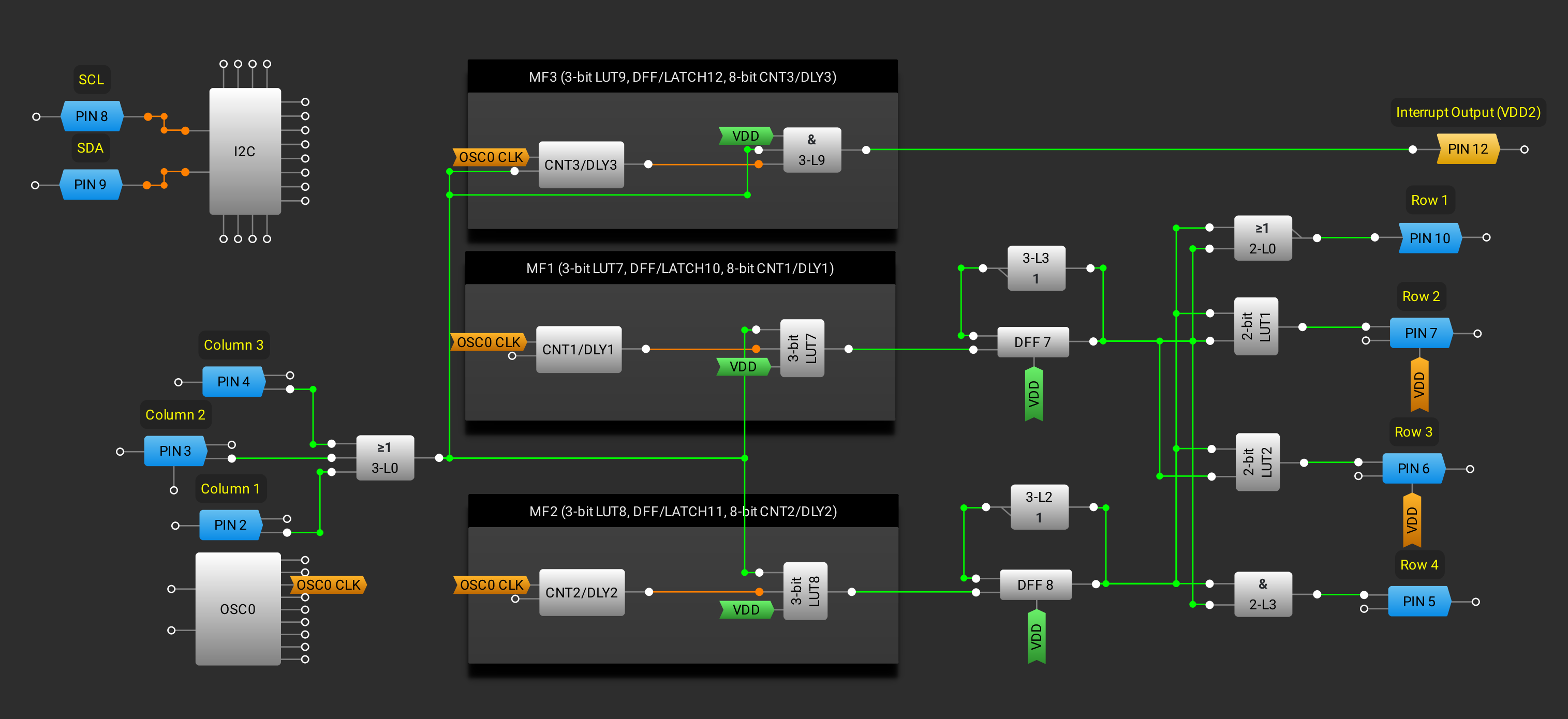
Interrupt pin from the keypad scanning could be set to 1.8 Volts, the row and columns could be 3.3 volts.
The gate-driver greenpak looks like this for now.

The gate-driver PWM inputs and fault output could be 1.8 volts. The h-bridge outputs, handset switch input and so on could be 3.3 volts.
After the prototype is finsihed I can start looking at what MCU to switch to but there is alot of work left to be done. I'll have to rewire the greenpaks and fix the bugs in the code then I can connect the bell ringer stuff. Will it ring?
Discussions
Become a Hackaday.io Member
Create an account to leave a comment. Already have an account? Log In.