 Tony Francis
The Fourier-Transform Infrared (FTIR) spectrometer is an icon of analytical chemistry, offering incredible speed and high-resolution spectral data. Every classic FTIR relies on a Michelson interferometer, and at the core of its precision is a tiny, red Helium-Neon (HeNe) laser acting as the ultimate, unmoving yardstick.
But what happens when your project demands optics that block that trusty red light? We faced this exact problem using Zinc Selenide (ZnSe) optics for specialized IR range work. Since ZnSe is opaque to visible light, the 632.8nm HeNe beam is useless. We must switch to a Near-Infrared (NIR) diode laser, which brings a major headache: instability.
A diode laser's wavelength shifts dramatically with temperature and current fluctuations. If the "ruler" you're using to measure the mirror's position changes size mid-scan, your spectral data is useless. Here is the hack—a way to precisely measure an unknown, unstable wavelength by first using a second, known laser to perfectly map the mirror's movement.
The HeNe Foundation: Position is Everything
In FTIR, the entire analysis depends on the computer knowing the exact mirror displacement ∆x when the IR signal is sampled.
The HeNe laser achieves this by producing an interference signal ∆x that cycles with the distance moved:
Since the HeNe wavelength λHeNe = 632.8nm is stable and known to extreme precision, every single fringe (cycle) corresponds to a mirror movement of exactly λHeNe /2 ≈ 316.4 nm. This stability is why the HeNe has been the Grandfather of FTIR; it converts a noisy, unpredictable motor movement into a perfectly known, equidistant sampling grid.
🛠️ The DIY Calibration Hack: Two Lasers, One Ruler
To solve the unstable NIR diode problem, we introduce a known, stable reference laser (let's call it the Red Laser, λRed). We monitor this stable reference simultaneously with the unknown measurement laser to account for both motor speed variation and the diode's mid-scan wavelength drift.
This hack breaks the complex problem (Unknown λ and v) into two manageable steps.
Step 1: Establish the Perfect Ruler (Mirror Position)
The mirror's instantaneous velocity v is the primary unknown. We eliminate it by using the known, stable λRed signal.
- Digitizing the Red Signal: We constantly monitor the fringes from the stable Red Laser with a dedicated detector.
- Mapping Displacement: We count the time ∆t between two adjacent maxima (fringes) in the Red signal. This movement corresponds to a mirror displacement of exactly ∆x = λRed / 2.
- Calculating Velocity (If Needed): While the ultimate goal is position, this process simultaneously reveals the instantaneous velocity: v = ∆x / ∆t
By tracking this process for every fringe, the digitized Red signal generates a high-precision, time-resolved map of the mirror's absolute position ∆x. Crucially, this position data is based only on the known λRed, making it independent of any motor speed instability.
Step 2: Calculate the Unknown Wavelength λGreen
With the mirror's position precisely mapped by λRed, we can now use that map to determine the wavelength of the unstable measurement laser, λGreen, from its simultaneously recorded fringe pattern.
- Set a Distance: Define a precise, calculated distance, ∆xTotal, mapped by a certain number of Red fringes (e.g., 1000 Red fringes, ∆xTotal = 1000 . λRed /2).
- Count Unknown Fringes: Over that exact same time interval and mirror distance ∆xTotal, we count the total number of fringes NGreen generated by the Green Laser.
- Solve for Wavelength: The distance ∆xTotal must also equal the total number of green fringes multiplied by the green half-wavelength:
Rearranging this formula gives us the instantaneous, precisely calibrated wavelength for the measurement laser:
📈 Conclusion: Precision Through Differential Measurement
By employing this dual-laser system, we achieve the accuracy of a HeNe-based system even with an unstable diode laser and ZnSe optics. The known reference laser (λRed) acts as the ruler to measure the mirror position (∆x), and that position measurement is then immediately used to measure the unknown laser's wavelength (λGreen).
This technique is a perfect example of how clever optical hacking and computation can overcome hardware limitations, allowing our DIY FTIR to deliver laboratory-grade wavenumber accuracy—no perfect HeNe required!
Seeing the distinct interference fringes from the green measurement laser and the red reference laser provides immediate visual proof of the system's ability to monitor both wavelengths simultaneously
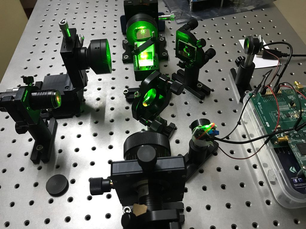
Michelson Interferometer with Green Laser

Michelson Interferometer with Red Laser
Discussions
Become a Hackaday.io Member
Create an account to leave a comment. Already have an account? Log In.