Now that we've got a delay line, it's time to set up the voltage booster! I figured running a neon bulb would be a nice demo, and super simple since it doesn't need an output rectifier. The neon lamp that I used is an A1B type, which should light at 70V.
For driving the delay line, a half-bridge or something along those lines would be a good idea. Maybe build with GaN devices for the frequencies at hand? But out of sheer laziness, and disregard for its intended use, I grabbed a high speed gate driver IC (UC27524D) and connected the cable connected to its outputs. While not very robust, it has the benefit of extreme simplicity. Here's the whole schematic.
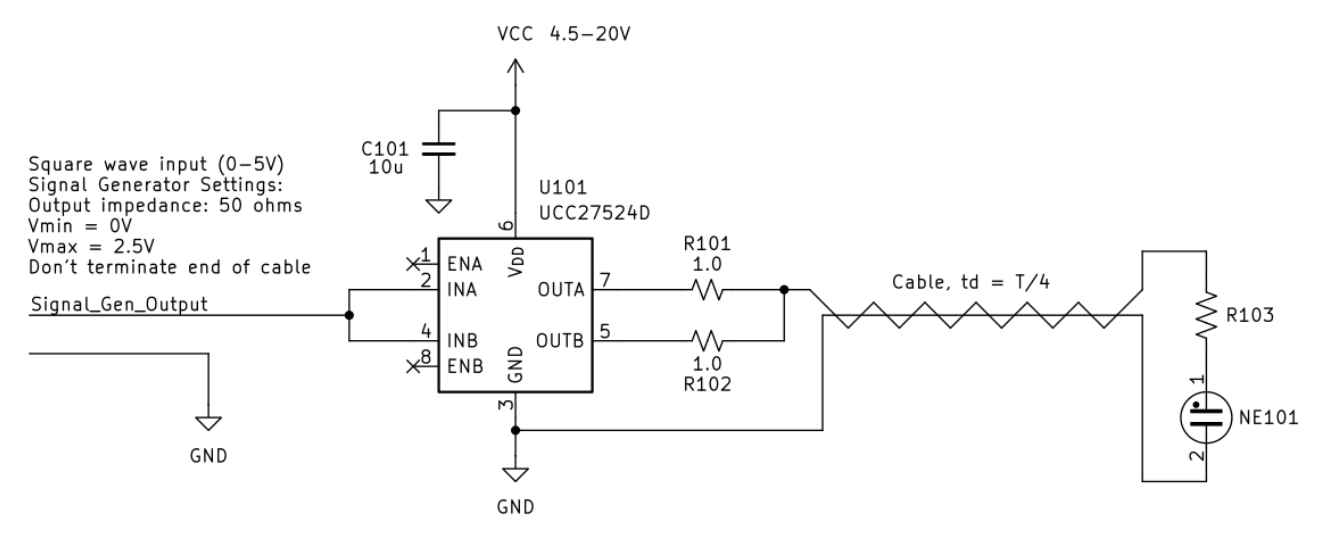
According to analysis and simulation, I should be able to run the neon lamp with a large series resistor - 100k. But that didn't work on the bench. However, I was able to get the lamp to light with a smaller or no series resistor. By cranking the supply to 15V, I was able to light two neon lamps in series. By that time, I had burnt up one of the chip's outputs, and just moved both resistors to the lone working output.

Discussions
Become a Hackaday.io Member
Create an account to leave a comment. Already have an account? Log In.