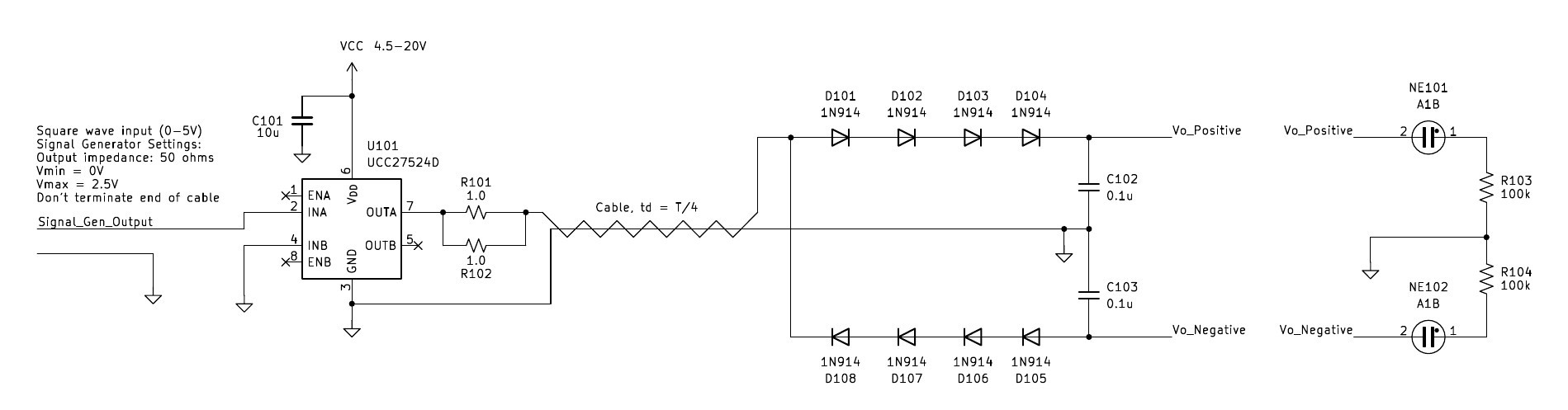
We can make our power converter more practical by rectifying the output. Further, with the output being bipolar, we can easily create a bipolar DC output voltage. One thing to be careful about is capacitive loading from the rectifier diodes, which the circuit can be rather sensitive to. I had a bunch of 1N914 diodes lying around, which have 4pF. This capacitance is a bit high, but can circumvented by stringing several in series. I used a voltage doubler rectifier to create the bipolar DC outputs. The upper string of diodes charges the upper capacitor to when the cable's output is positive, and the lower string charges the lower capacitor when the cable output is negative.
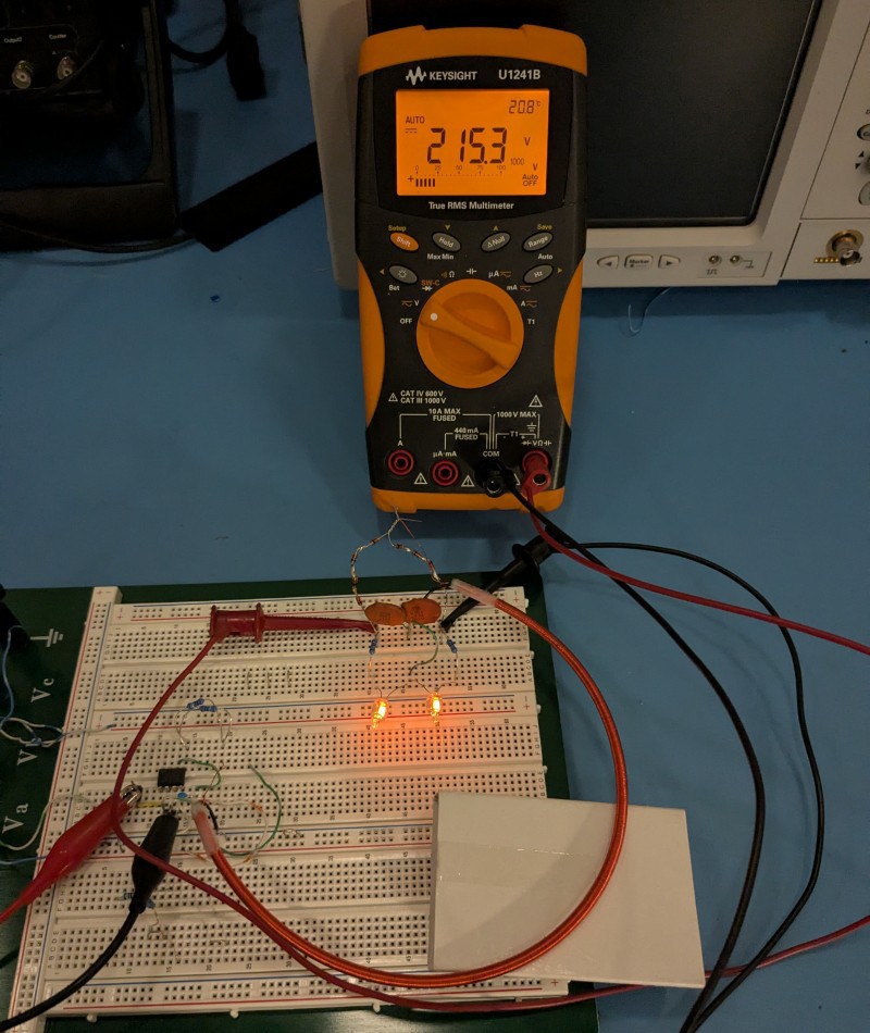
The converter was much less finicky with the rectified output. I was able to easily power two neon lamps with 100k series resistors. The DMM is hooked up to measure the total voltage, from Vo_positive to Vo_negative. The driver (U101)'s power supply was set to 10V. I adjusted the frequency for maximum voltage. The optimal frequency was 10.3MHz. Note that the input ends of the diode strings are "air wired" to the cable's output to avoid adding capacitance from the breadboard.
Discussions
Become a Hackaday.io Member
Create an account to leave a comment. Already have an account? Log In.