Close
0%
0%

IOTA STATION- A Mini PC with Giant Rotary Knob

A Mini PC powered by Lattepanda IOTA SBC

Similar projects worth following
0 followers
Greetings everyone, and welcome back.
Meet IOTA STATION, a super-compact mini PC built completely from scratch, featuring a giant rotary knob used to control system volume as well as page scrolling up and down.

At the heart of this mini PC is the LattePanda IOTA, powered by an Intel N150 4-core processor, capable of handling far more than just basic tasks. By using the LattePanda IOTA’s onboard RP2040 co-processor, we were able to implement the HID-based volume control and scrolling encoder functionality.

The entire project was modeled in Fusion 360, then 3D printed and assembled.

HARDWARE- LATTEPANDA IOTA

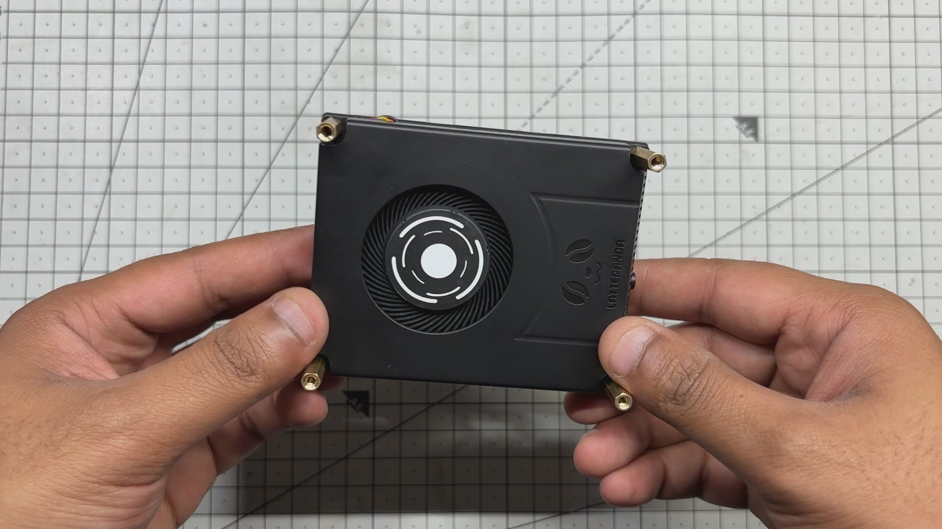
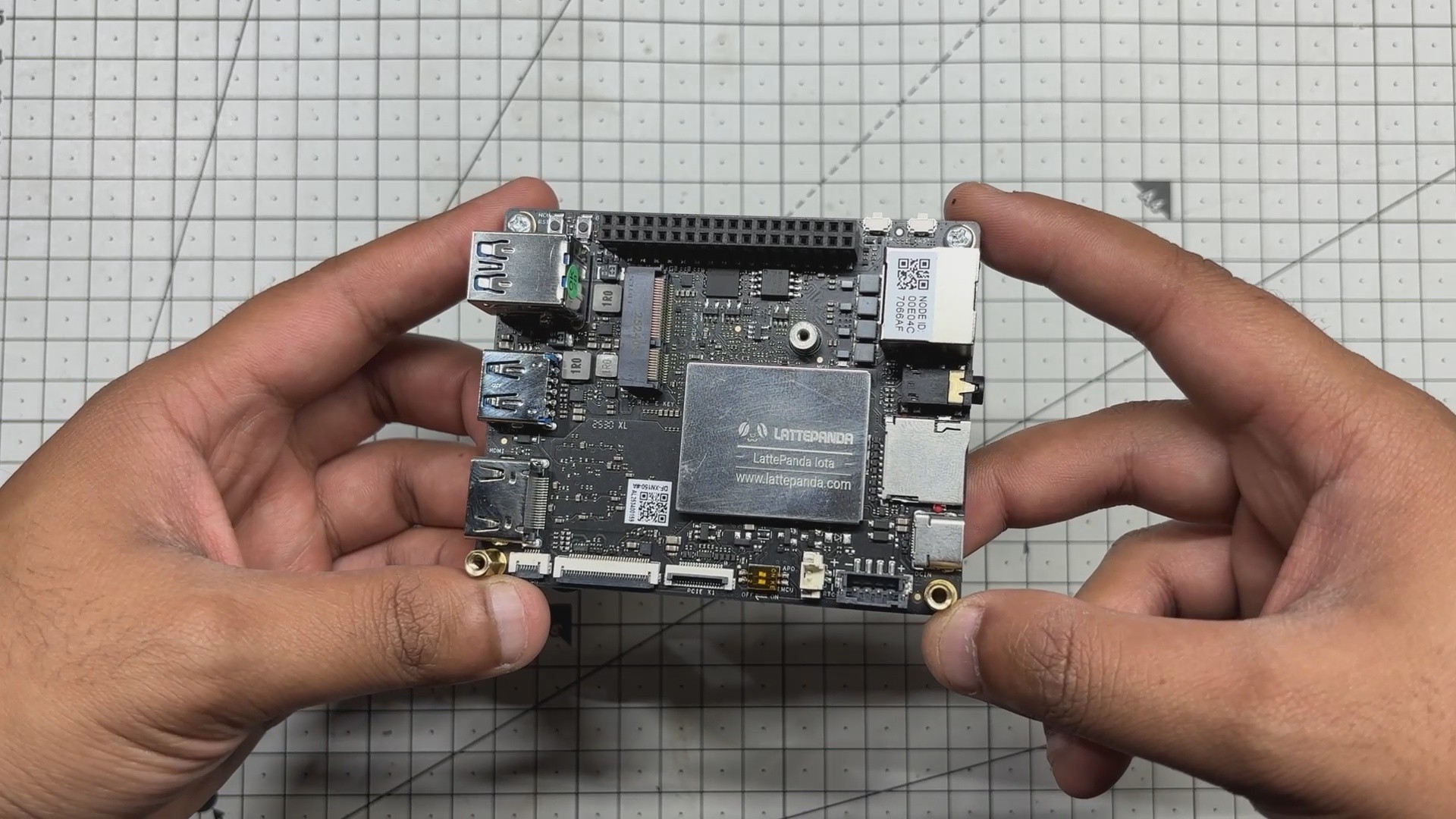
At the heart of this project is the LattePanda IOTA, a compact yet powerful x86 single-board computer designed for edge computing, embedded applications, and serious maker projects. I’m using the 16 GB RAM variant, which provides significantly more headroom than most SBCs of this size.

The LattePanda IOTA shares the same form factor as the original LattePanda V1, but thanks to its newer Intel N150 processor with 4 cores and 4 threads, it can handle much heavier workloads. I even experimented with running Bazzite on it, effectively turning it into a low-power Steam Machine.

We selected the IOTA for this project to build a super-compact mini PC capable of running Windows, making it suitable for general-purpose tasks such as web browsing.

Key Specifications (16 GB Variant)

  • Processor: Intel x86 CPU (energy-efficient, PC-class architecture)
  • Memory: 16 GB LPDDR4 RAM
  • Storage: Onboard eMMC (expandable via M.2 Port)
  • Connectivity: USB ports for peripherals, HDMI for display output, Ethernet + Wi-Fi (model dependent)

You can check out more about this board from Lattepanda's wiki page.

https://docs.lattepanda.com/content/iota_edition/get_started/

DESIGN

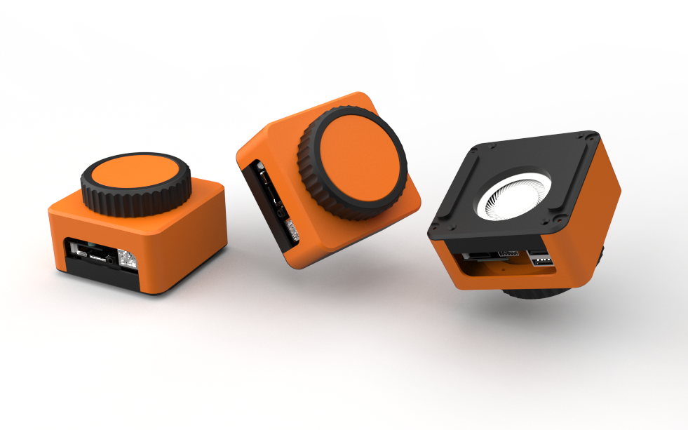
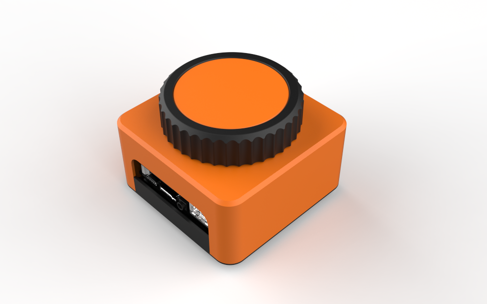
The main idea behind the design of this mini PC was simple: we wanted a giant rotary knob that actually houses the PC inside it.

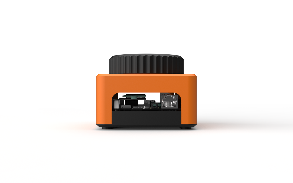
We started by creating a 3D model of the LattePanda, and around it we designed a cuboid-shaped enclosure with a large rotary knob mounted on the top. Openings were added on the left and right sides to allow easy access to the LattePanda’s I/O ports.

To ensure that all parts could be 3D printed without support material, the rotary knob mechanism was designed as a detachable assembly. This mechanism is connected to the main body using five M2 screws. The holder-like internal structure is secured to the main body from the inside, and the rotary knob is mounted on top of this holder.

The rotary knob itself is made from two separate parts that are pressure-fitted together. Printing the knob in two different colors gives it a dual-tone black and orange finish, inspired by our mechanical keyboard, which is also used later in the demo. Inside the enclosure, the rotary encoder is positioned and held securely using a retaining bracket.

The main body is attached to the base using four M2 screws inserted from the bottom. The LattePanda itself is mounted to the base using the provided mounting holes, secured with M2.5 bolts.

Since the base includes an opening for the LattePanda’s heatsink air intake, we also designed two small lift parts that raise the entire PC a few millimeters off the ground to improve airflow. These parts are secured using alignment pins modeled on their backside. Matching holes were added to the base, allowing the parts to be aligned and pressure-fitted into place.

3D PARTS

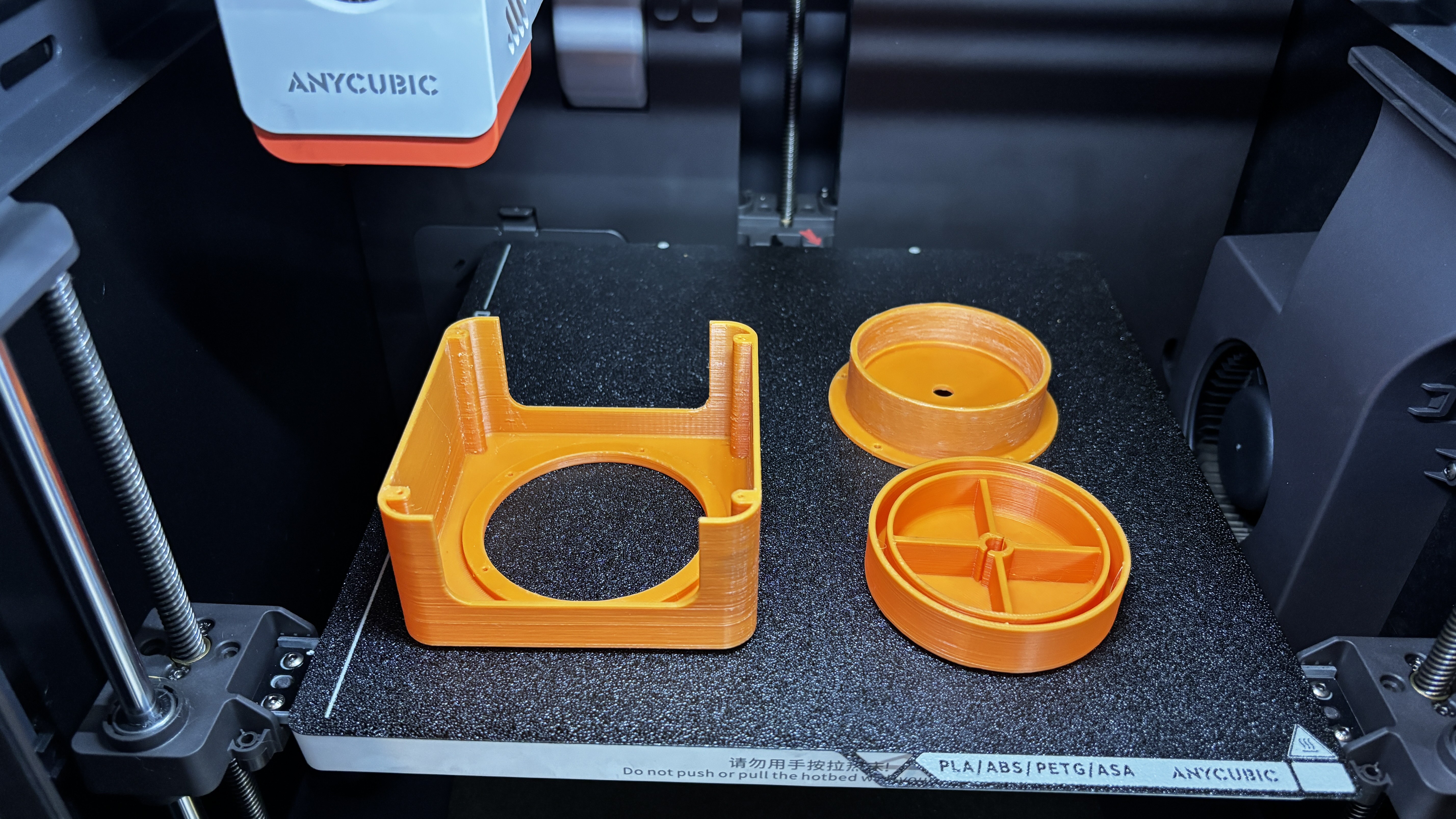
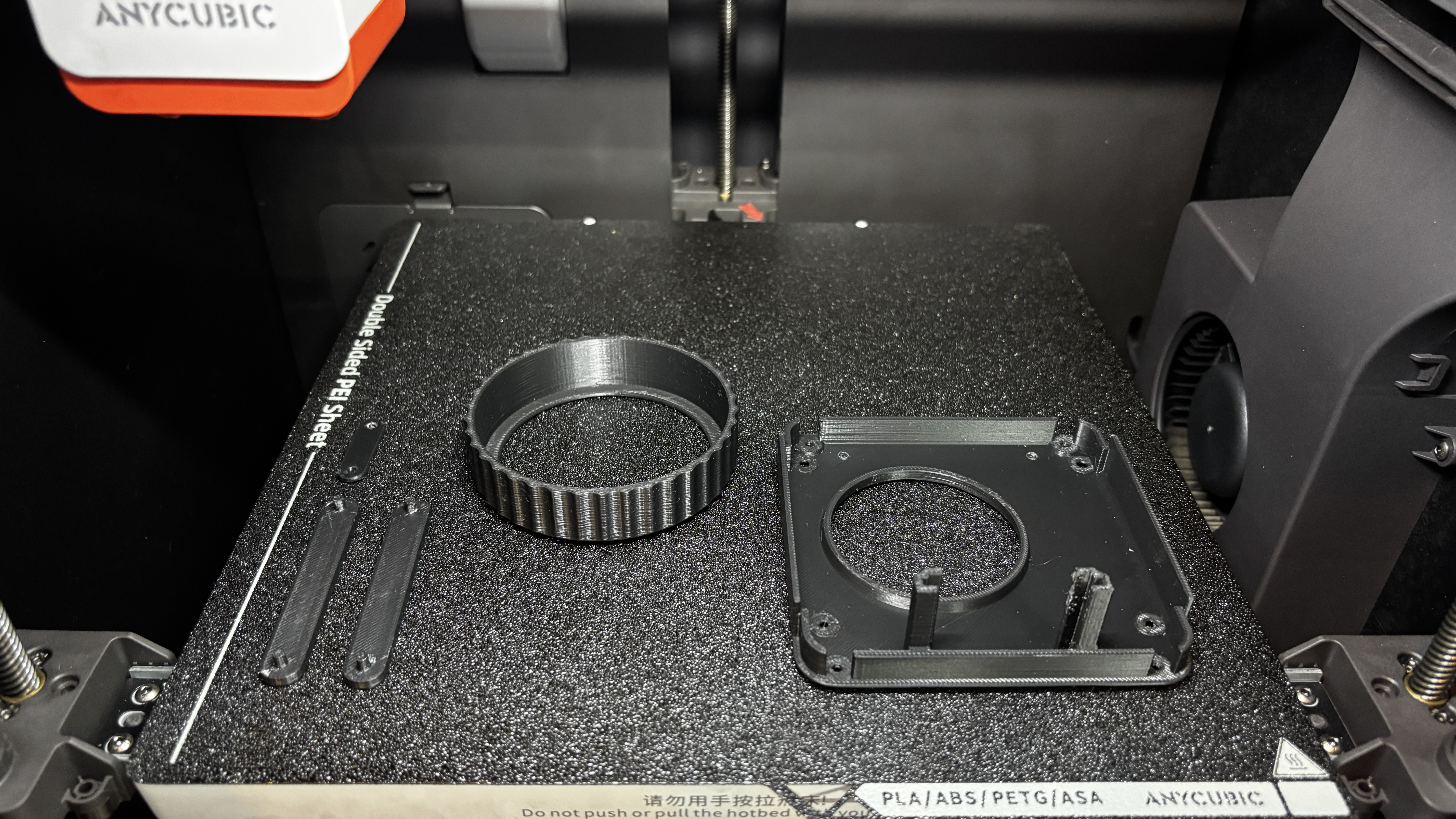
All parts were exported as mesh files before printing. We first 3D printed the outer part of the knob using black Hyper PLA, along with the base, two base resting parts, and the encoder holder. Orange Hyper PLA was used to print the encoder knob and its fixture, as well as the main body.

All components were printed with a 0.16 mm layer height and 25% infill, using my Anycubic Kobra S1 for printing all the parts.

PCB DESIGN

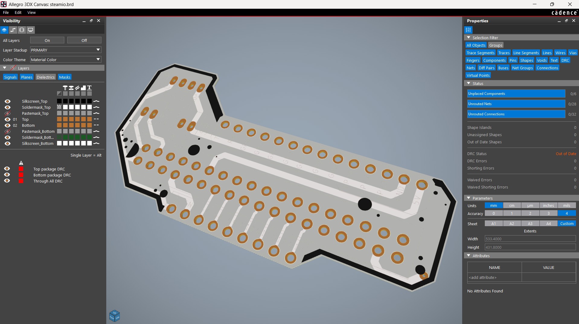
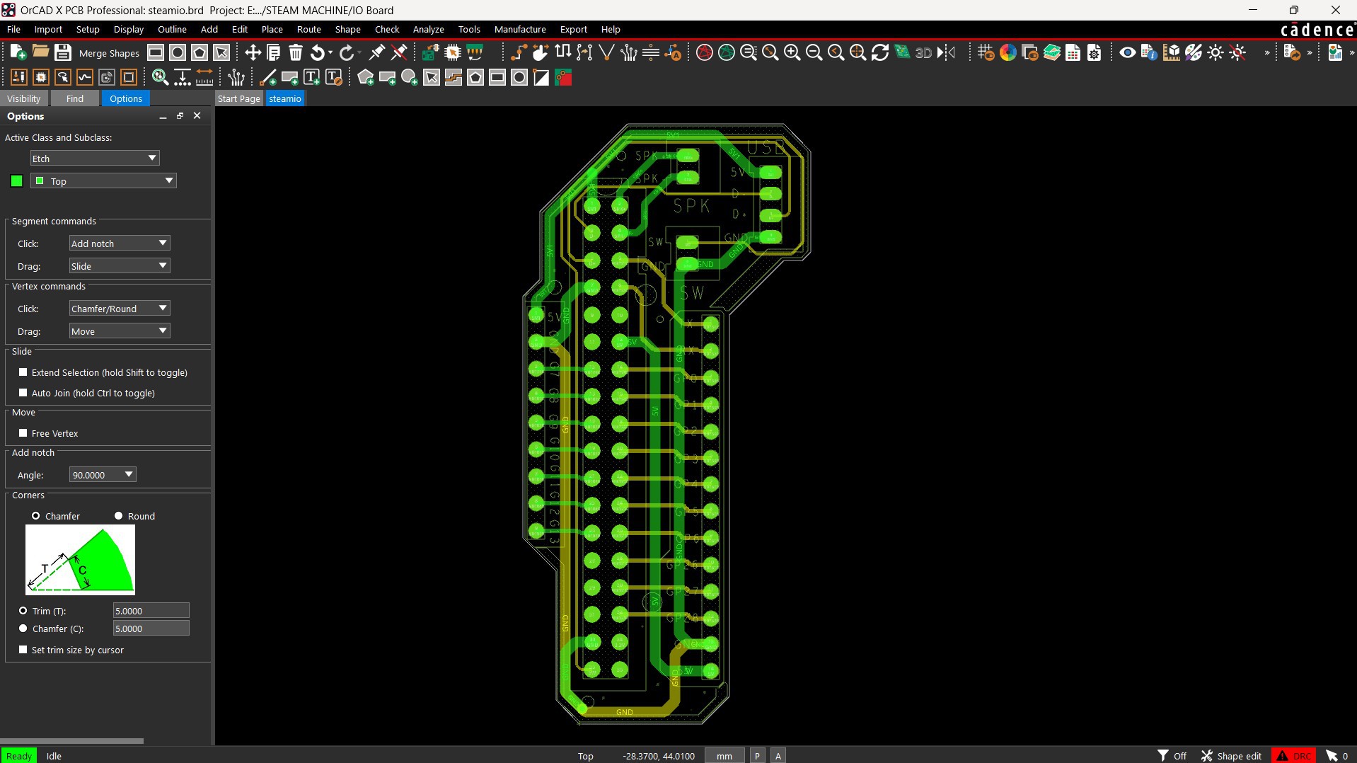
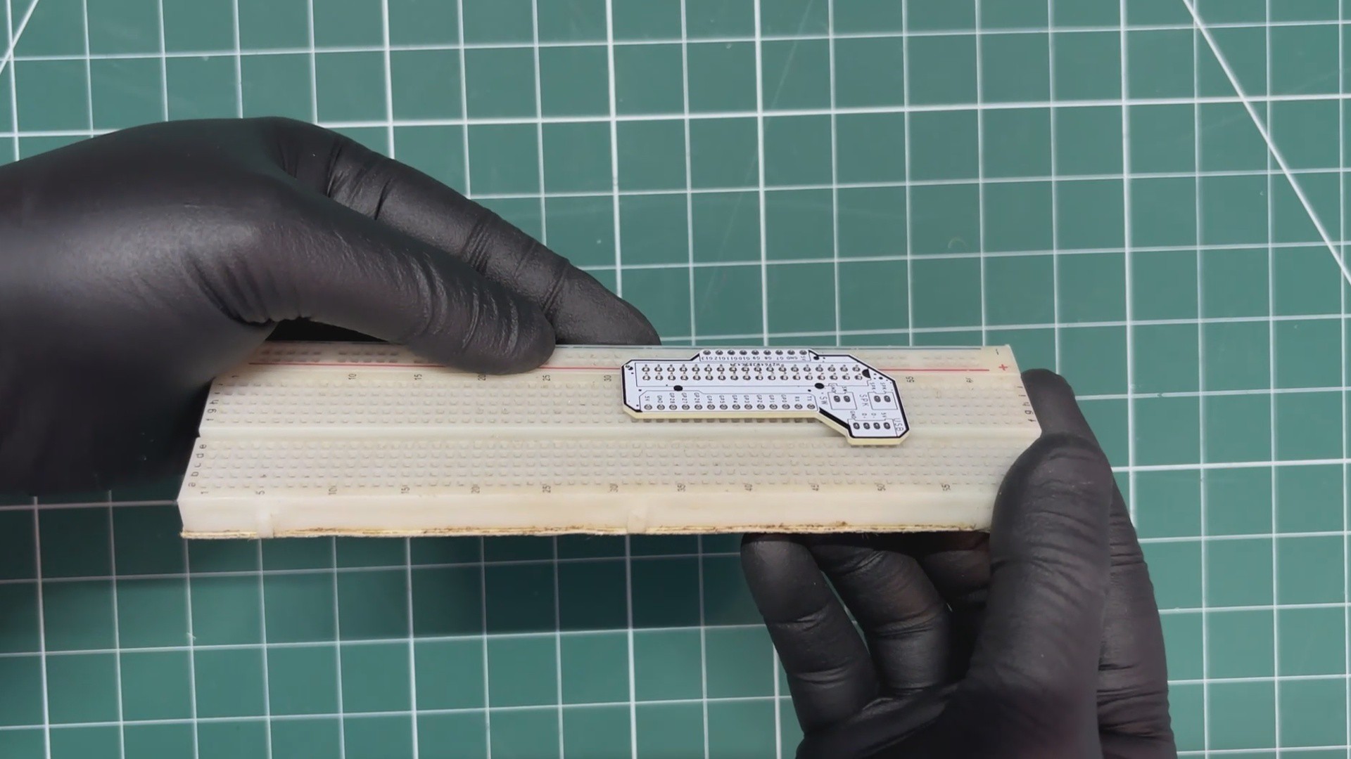
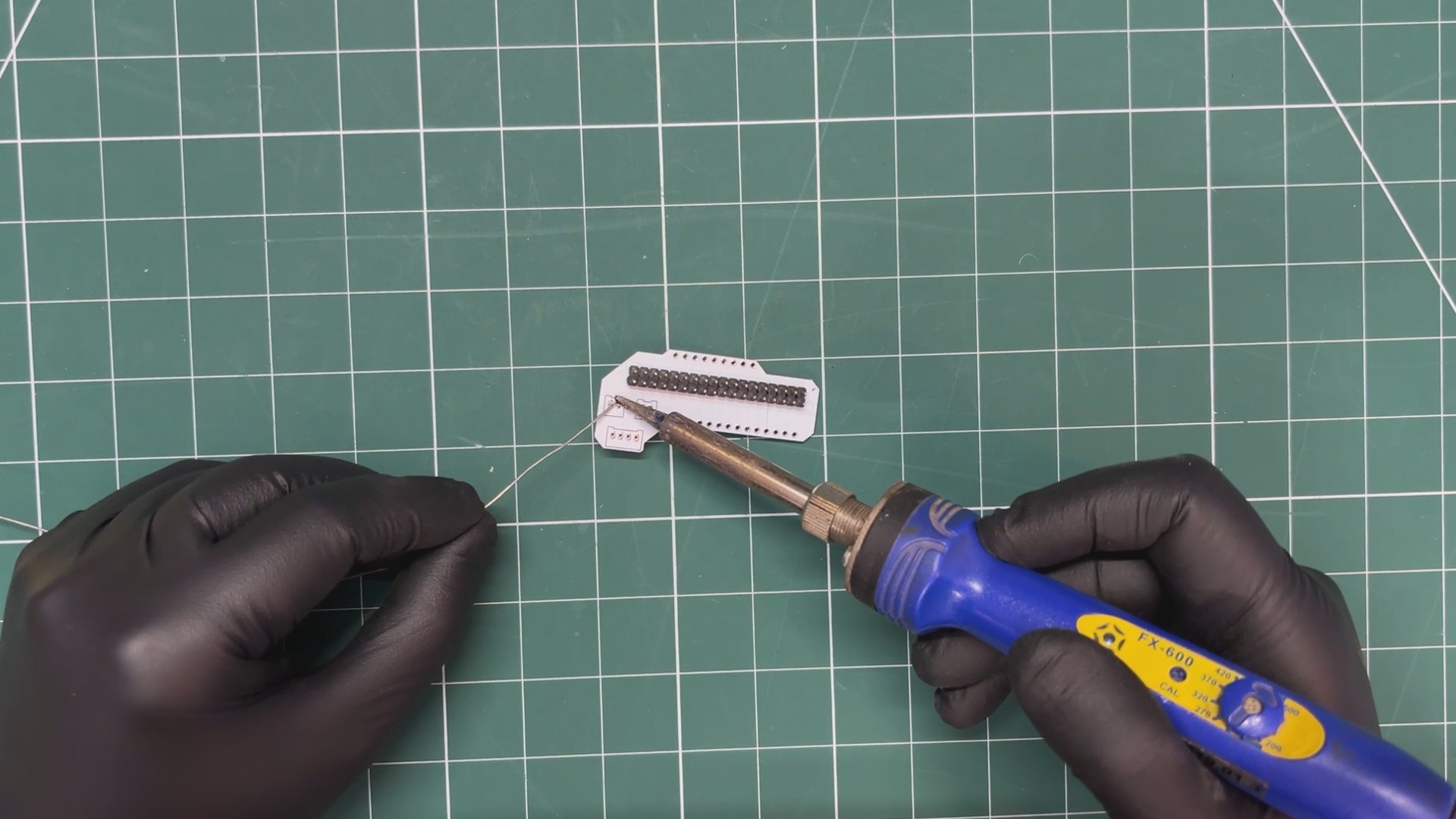
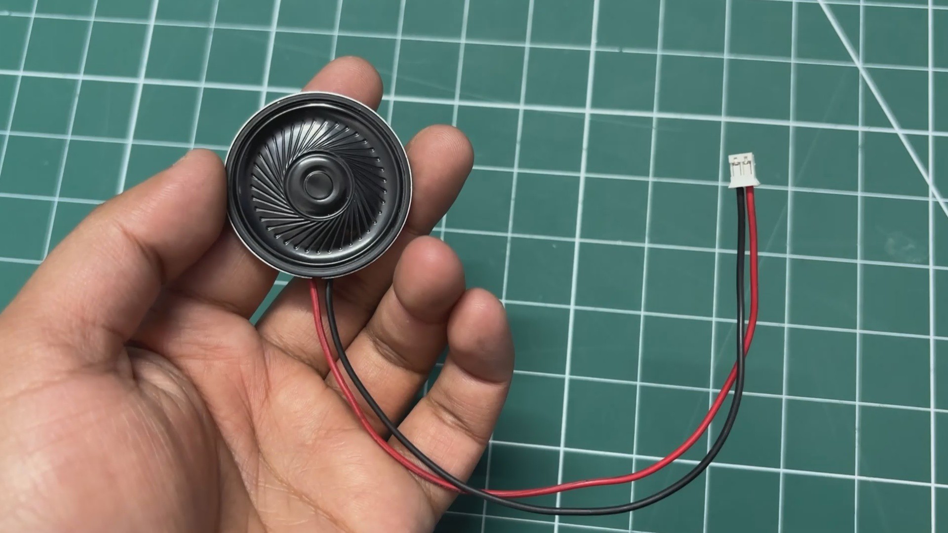
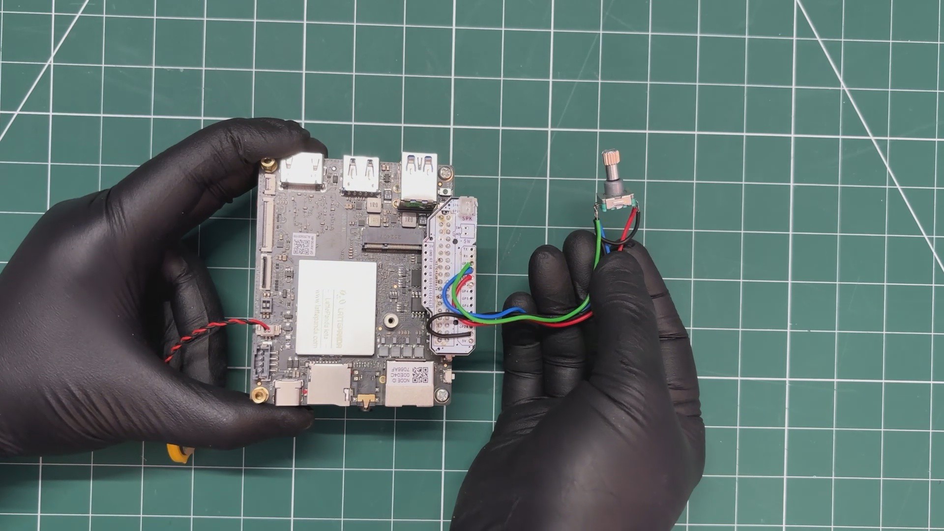
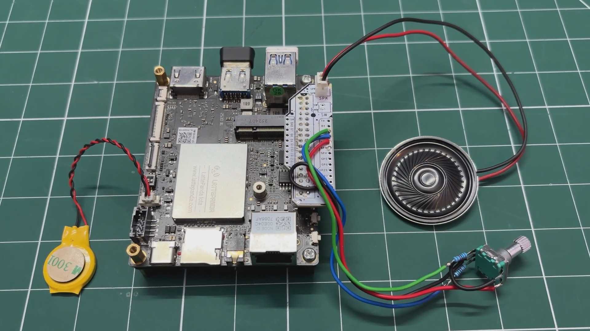
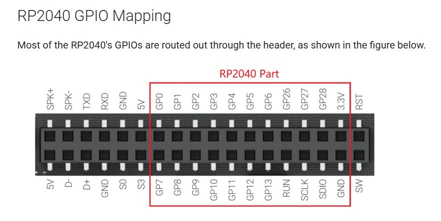
The PCB design for this project was super simple. We just needed a cleaner and more organized way to use the LattePanda’s GPIO pins for connecting the encoder and the speaker output. So the best solution was to design a breakout board that brings out all the I/O pins of the LattePanda.

We made this PCB in a way that it can also be reused in future projects, making it a handy and practical addition beyond this build.

PCBWAY SERVICE

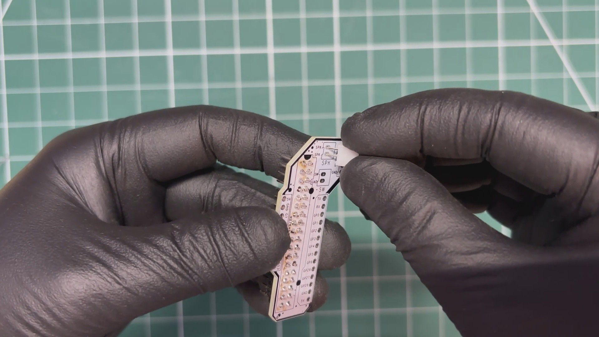
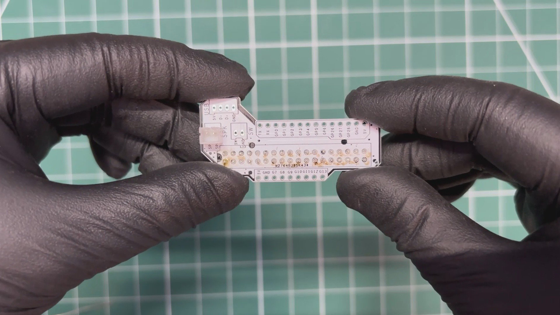
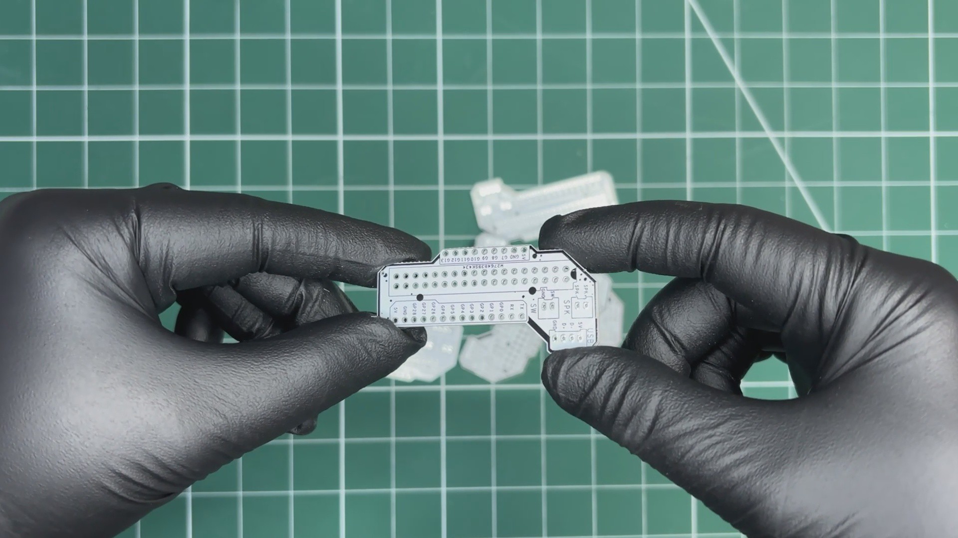
We uploaded the Gerber files to PCBWay’s quote page and placed an order for a white solder mask PCB with black silkscreen.

PCBs were received within a week, and the PCB quality was outstanding. Here, we added a few design elements on the board's silkscreen layer to...

Read more »

Lattepanda Mini PC v4.step

step - 25.95 MB - 02/20/2026 at 17:20

Download

Lattepanda Mini PC v4.f3d

fusion - 20.06 MB - 02/20/2026 at 17:20

Download

INNER.stl

Standard Tesselated Geometry - 2.24 MB - 02/20/2026 at 17:19

Download

Upper Body.stl

Standard Tesselated Geometry - 1.31 MB - 02/20/2026 at 17:19

Download

BASE.stl

Standard Tesselated Geometry - 1.71 MB - 02/20/2026 at 17:19

Download

View all 9 files

  • 1
    PCB ASSEMBLY
    • We begin the assembly process by placing two CON18 male header pins side by side on a breadboard.
    • The PCB is then placed over the header pins, and the connections are secured by soldering the leads using a soldering iron. This is a clever and reliable method for soldering breakout boards or modules, as the breadboard helps keep the header pins perfectly straight while soldering.
    • Next, we place a CON2 connector onto the speaker pads on the breakout board.
    • After flipping the board over, we solder the connector in place.
  • 2
    ENCODER WIRING
    • We connected GPIO 0 and GPIO 1 to the encoder’s A and B pins through 10 kΩ resistors placed in series.
    • The middle pin of the encoder, along with one pin of the encoder’s push button, was connected to the GND of the LattePanda.
    • The remaining encoder switch pin was connected to GPIO 3.
    • For sound output, we connected an 8-ohm, 0.5-watt round speaker to our setup using the onboard JST connector, simply plugging the speaker directly into it.
    • We used single-core jumper wires for all the connections, and once the wiring was complete, we moved on to the code uploading process.
  • 3
    MAIN CODE
    • Before uploading the code, we first set up the RP2040 in the Arduino IDE. We navigated to File>Preferences and added the below JSON URL to the Additional Boards Manager URLs.

    https://github.com/earlephilhower/arduino-pico/releases/download/global/package_rp2040_index.json

    • Next, we opened the Boards Manager, searched for Raspberry Pi Pico, and installed the board package by Earle Philhower.
    • After installing the Raspberry Pi Pico core for the Arduino IDE, we uploaded our main code to the onboard RP2040 co-processor.
    • To put the RP2040 into boot mode, we pressed and held the BOOTSEL button, then pressed and released the RST button, and finally released the BOOTSEL button. The operating system then detected the RP2040 as a new USB Mass Storage Device.

    We uploaded the below code into our coprocessor.

    #include <Adafruit_TinyUSB.h>
    // ================== PINS ==================
    #define ENC_A   0
    #define ENC_B   1
    #define ENC_BTN 2
    // ================== HID ===================
    Adafruit_USBD_HID hid_consumer;
    Adafruit_USBD_HID hid_keyboard;
    uint8_t const consumer_desc[] = {
    TUD_HID_REPORT_DESC_CONSUMER()
    };
    uint8_t const keyboard_desc[] = {
    TUD_HID_REPORT_DESC_KEYBOARD()
    };
    // ================== MODE ==================
    bool volumeMode = true;
    bool lastBtn = HIGH;
    // ================== ENCODER (DETENT LOCK) ==================
    int8_t readEncoder() {
    static uint8_t last = 0b11;
    static int8_t count = 0;
    uint8_t now = 0;
    if (digitalRead(ENC_A)) now |= 1;
    if (digitalRead(ENC_B)) now |= 2;
    if (now != last) {
    if ((last == 0b11 && now == 0b01) ||
    (last == 0b01 && now == 0b00) ||
    (last == 0b00 && now == 0b10) ||
    (last == 0b10 && now == 0b11))
    count++;
    if ((last == 0b11 && now == 0b10) ||
    (last == 0b10 && now == 0b00) ||
    (last == 0b00 && now == 0b01) ||
    (last == 0b01 && now == 0b11))
    count--;
    last = now;
    }
    if (now == 0b11) {
    if (count >= 4) { count = 0; return +1; }
    if (count <= -4) { count = 0; return -1; }
    count = 0;
    }
    return 0;
    }
    // ================== HID SEND ==================
    void sendVolume(uint16_t key) {
    hid_consumer.sendReport(0, &key, sizeof(key));
    delay(2);
    uint16_t zero = 0;
    hid_consumer.sendReport(0, &zero, sizeof(zero));
    }
    void sendKey(uint8_t keycode) {
    uint8_t press[8] = {0};
    uint8_t release[8] = {0};
    press[2] = keycode;
    hid_keyboard.sendReport(0, press, sizeof(press));
    delay(2);
    hid_keyboard.sendReport(0, release, sizeof(release));
    }
    // ================== SETUP ==================
    void setup() {
    pinMode(ENC_A, INPUT_PULLUP);
    pinMode(ENC_B, INPUT_PULLUP);
    pinMode(ENC_BTN, INPUT_PULLUP);
    hid_consumer.setReportDescriptor(consumer_desc, sizeof(consumer_desc));
    hid_consumer.begin();
    hid_keyboard.setReportDescriptor(keyboard_desc, sizeof(keyboard_desc));
    hid_keyboard.begin();
    while (!TinyUSBDevice.mounted()) delay(10);
    }
    // ================== LOOP ==================
    void loop() {
    // Button toggle
    bool btn = digitalRead(ENC_BTN);
    if (lastBtn == HIGH && btn == LOW) {
    volumeMode = !volumeMode;
    delay(300);
    }
    lastBtn = btn;
    // Encoder
    int8_t move = readEncoder();
    if (move != 0) {
    if (volumeMode) {
    if (move > 0)
    sendVolume(HID_USAGE_CONSUMER_VOLUME_INCREMENT);
    else
    sendVolume(HID_USAGE_CONSUMER_VOLUME_DECREMENT);
    } else {
    if (move > 0)
    sendKey(HID_KEY_PAGE_DOWN);
    else
    sendKey(HID_KEY_PAGE_UP);
    }
    }
    }

    Before using this sketch, we installed adafruit TinyUSB library before uploading, after uploading our RP2040 coprocessor turns into a USB HID device that can function as both a media controller and a keyboard input.

    The rotary encoder is read using a detent-locked quadrature decoding method, ensuring that each physical click of the encoder results in only one action. By default, the encoder controls system volume, and pressing the encoder button toggles the mode between volume control and page scrolling.

    In volume mode, rotating the encoder sends USB consumer control commands to increase or decrease the system volume, while in scroll mode, it sends keyboard Page Up and Page Down key events.

View all 9 instructions

Enjoy this project?

Share

Discussions

Does this project spark your interest?

Become a member to follow this project and never miss any updates