 Aaron Qian
Overview
This project aims to transform cheap SG90/MG90S-class servos into fully networked smart actuators by adding:
- sensor feedback
- cascade control loops (current → velocity → position)
- a DYNAMIXEL-style serial protocol
- a bare-metal Rust firmware stack
Rather than relying on expensive commercial smart servos, this platform provides a low-cost, open, and hackable alternative. It gives students, hobbyists, and resource-limited builders the tools to explore:
- Cheaper way to build higher end robotics projects
- motor current and voltage sensing
- system identification and model building
- PID tuning and control theory
- bus protocols and multi-servo networking
To ground it in numbers:
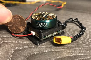
- A small 4-legged robot with 12 smart servos built from commercial DYNAMIXEL-style actuators can easily cost $300–$400+ just in servos.
- The same robot built on this platform, using MG90S clones from AliExpress (≈ $2.50 each) plus a custom smart-servo board in the $2–$4 range per joint, brings the per-actuator cost down to roughly $4.50–$6.50.
- For 12 joints, that’s on the order of $55–$80 in actuators instead of several hundred dollars — making it an accessible option for students, hobbyists, and resource-limited builders.
By upgrading a $2–$3 servo into a capable, addressable actuator, this project works toward democratizing robotics for everyone, especially builders who can’t casually sink a few hundred dollars into “just the servos.”
Spec
High-level target spec for the v0.x platform:
Mechanical / Base Servo
- Base mechanism: SG90/MG90S-class micro servos
- Metal gears preferred (survivability during experiments)
- No mechanical modifications beyond swapping the control board
Electronics
- MCU: small RISC-V CH32V006 ($0.22 a piece)
- Motor driver: H-bridge (DRV8xxx class)
- Feedback options:
- stock potentiometer
- onboard current sensor
- future: internal reflective IR encoder for position detection
- Current sensing: shunt + MCU OPA & PGA
- Communications bus:
- Phase 1: half-duplex UART, DYNAMIXEL-style (TTL)
- Future: RS-485 and/or CAN-FD variants
Firmware / Control
- Language: Rust — bare-metal, PAC-level drivers
- Control structure: cascade control
- outer loop: position
- middle loop: velocity
- inner loop: current/torque (where hardware allows)
- Features:
- addressable servos on a shared bus
- register read/write (pos, vel, temp, voltage, etc.)
- basic homing / calibration
- soft limits and error reporting
Protocol
- Packet-based, inspired by DYNAMIXEL 2.0:
- header → ID → length → instruction → params → checksum
- instructions: PING, READ, WRITE, SYNC_WRITE, BULK_READ
- “Backwards-inspired,” not backwards-compatible
- Designed so a PC, microcontroller, or SBC can control many servos over one UART
Architecture
The Smart Servo project is organized into mechanical, hardware, firmware, protocol, and tooling layers. Only components inside the servo belong to the core architecture. External sensors and rigs for system identification live under Tooling & Measurement Rigs.
1. Mechanical & Enclosure Layer
Planned
- Stock hobby servo housing and gear train
- Standard spline and servo horn
Future
- 3D-printed internal brackets for future sensing modules
This layer governs physical constraints, gear clearance, and mechanical integration.
2. Hardware Layer (Servo Electronics)
The smart control board replaces the stock PCB and becomes the electrical core of the servo:
- MCU: CH32V006
- H-bridge: DRV8xxx or similar
- Feedback: stock rotary potentiometer
- Current sensing: low-side shunt
- Communications: half-duplex UART (DYNAMIXEL-style), future RS-485 / CAN-FD
- Power: 3.3V - 8.4V range for 1S - 2S LiPo battery.
3. Feedback & Sensing Layer
Planned
- Rotary potentiometer (primary feedback)
- Current sensor via low side shunt
- Motor terminal voltage sensing (voltage divider)
- Input Voltage sensing (voltage divider)
- NTC...

 Christopher Xu
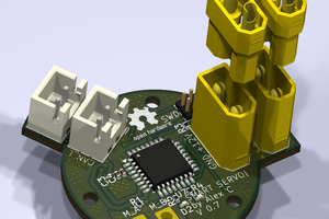
 Gabriel-Alexandru Constantinescu
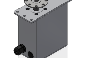
 patchartrand
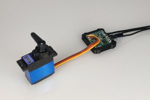
 pat92fr