Close
0%
0%

AranyaLink

An open-source, $10 forest fire detection mesh network using ESP32 & ESP-NOW. Autonomous, infrastructure-free, and self-healing.

Similar projects worth following
0 followers
AranyaLink is a decentralized, low-cost wildfire early-warning ecosystem built for communities exposed to high environmental risk but lacking access to multi-million dollar infrastructure budgets.
The system relies on a flat, peer-to-peer mesh architecture built with standard ESP32 microcontrollers running the ESP-NOW protocol. Instead of routing to a central internet gateway or cellular base station—vulnerable points of failure likely to get consumed by an advancing fire front—every independent node functions simultaneously as an ambient detector and a routing repeater.

Introduction

Every year, wildfires cost the United States between $394 billion and $893 billion. Globally, the 2024–25 fire season burned an area larger than India and released 8 billion tonnes of CO₂. The 2025 Southern California fires alone caused $140 billion in economic damage in a matter of weeks.
The technology to catch fires early exists. A professional IoT sensor mesh can detect a smoldering fire in under 3 minutes. A single air tanker dispatched at minute two costs $14,000 per hour. A fire crew deployed at hour three costs $1.3 million per week in wages alone. The math is not complicated — early detection saves everything downstream.
The problem is access. A state-wide sensor network costs $36 million. A single AI camera station runs $50,000 per year. Satellite subscriptions start at $12,000 annually per municipality. The communities living closest to fire-prone forests — in India, Indonesia, Brazil, rural Africa — have none of it. Roughly 30% of forest fires go undetected in their incipient stages, not because the science is hard, but because the price tag is prohibitive.

AranyaLink: Open-Source Forest Fire Detection Mesh Network

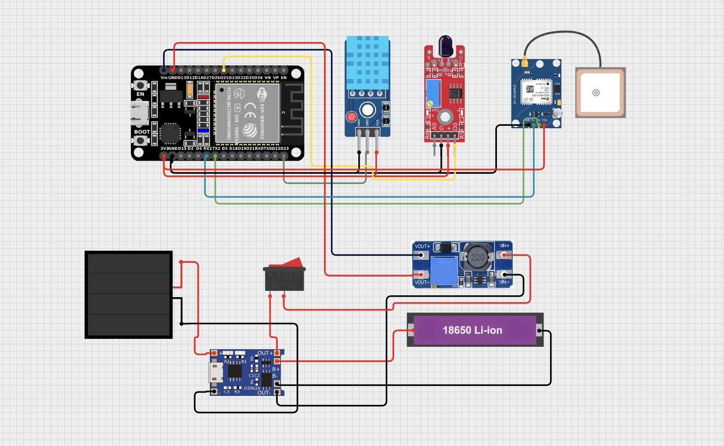
Aranya (अरण्य) is the Sanskrit word for forest. In the ancient world, it represented a philosophy of radical environmental interdependence—the core truth that when you protect the forest, you protect everything the forest sustains. AranyaLink is an infrastructure-free, low-cost wildfire early-warning platform designed to democratize conservation technology. Built on standard ESP32 microcontrollers, each fully autonomous node costs less than $10 to manufacture and requires absolutely zero cellular network connections, internet routers, central clouds, or subscription fees.

System Architecture & Network Logic


Traditional early-warning deployments rely on a standard hub-and-spoke configuration, where every remote element pushes telemetry up to a central gateway. In a massive wildfire, that central gateway is the exact piece of tracking infrastructure most likely to be overrun and destroyed by the expanding fire front, killing the entire network instantly.
AranyaLink completely removes the central coordinator. It utilizes a completely flat, decentralized, peer-to-peer routing topology running over the ESP-NOW radio protocol. Every node functions simultaneously as a localized detection terminal and an independent repeater node.

[ Ignition Event ] 
       │
       ▼
 [ Node 1 (Detect) ] ──(ESP-NOW Broadcast)──► [ Node 2 (Verify & Relay) ]
                                                      │
                                             (ESP-NOW Multi-Hop Link)
                                                      │
                                                      ▼
                                           [ Node 3 (Verify & Relay) ]
                                                      │
                                             (Canopy Perimeter Exit)
                       ...
Read more »

Wiring_diagram .jpg

Connection diagram of the node

JPEG Image - 564.15 kB - 06/09/2026 at 05:58

Preview

  • 2 × Esp32 devkit v1 Main microcontroller of the project
  • 1 × Dht11 For sensing temperature
  • 1 × IR flame sensor For sensing infrared heat signature for flames
  • 1 × 18650 lipo battery To power the whole circuit electronics
  • 1 × 1-2w mini solar panel Keeping the battery charged

View all 6 components

  • 1
    Step 1: Wiring the Sensor Node

    Follow the system connection matrix to wire your sensory peripherals directly to a 30-pin ESP32 DevKit v1. All peripherals operate natively at 3.3V logic levels:

     DHT11 VCC connects directly to the ESP32 3V3 power rail.

     DHT11 DATA connects to GPIO 23.

     DHT11 GND connects to the common system GND plane.

     IR Flame Sensor VCC connects directly to the ESP32 3V3 power rail.

     IR Flame Sensor DO connects to GPIO 25. This digital signaling output pin drops to an active LOW state whenever infrared radiation from an open flame is verified.

     IR Flame Sensor GND connects to the common system GND plane.

     Neo-6M GPS VCC connects to 3V3.

     Neo-6M GPS TX connects directly to GPIO 16 (mapped to hardware Serial2 RX).

     Neo-6M GPS RX connects directly to GPIO 17 (mapped to hardware Serial2 TX).

     Neo-6M GPS GND connects to the common system GND plane.

    Note: The primary Ground Control Station (GCS) base unit requires no sensor wiring layouts; it operates as a standalone bare ESP32 linked directly to a laptop via its USB interface connection.

  • 2
    Step 2: Setting Up the IDE Environment & Libraries
    1. Open your Arduino IDE application interface.
    2. Navigate directly to File > Preferences and add the official Espressif development link to your Additional Boards Manager URLs field:

    https://raw.githubusercontent.com/espressif/arduino-esp32/gh-pages/package_esp32_index.json

     3. Open Tools > Board > Boards Manager, run a targeted search for esp32 by  Espressif Systems, and initialize the download. This framework provides native, underlying libraries for both WiFi.h and esp_now.h.

     4. Access Sketch > Include Library > Manage Libraries and install the following toolkits:

    • DHT sensor library (distributed by Adafruit)
    • Adafruit Unified Sensor (underlying dependency layer)
    • TinyGPS++ (distributed by Mikal Hart)

     5. Connect your device to a data port, select Tools > Board > ESP32 Dev Module, and establish the mapped active COM Port link.

  • 3
    Step 3: Configuring & Flashing Firmware Nodes

    Download the complete core codebase files directly from the repository index. For every independent sensor node deployed into your canopy grid, you must manually iterate the variables inside the configuration block at the top of the AranyaLink_Node.ino file before hitting upload.

    // Change these parameters sequentially for every individual hardware node deployed
    
    #define NODE_ID 1 // Unique integer tracking index per node: 1, 2, 3, 4...
    
    #define NODE_LAT_FALLBACK 12.345678 // Default deployment latitude coordinate quadrant
    
    #define NODE_LON_FALLBACK 98.765432 // Default deployment longitude coordinate quadrant
    
    #define TEMP_THRESHOLD 50.0f // Trigger target in °C (raise to 55.0f-60.0f in extreme summer environments)
    
    #define FLAME_ACTIVE LOW // Low setting matches standard KY-026 active outputs
    
    
    •   NODE_ID: Every independent field module must carry its own standalone sequence integer to map verification traces accurately across data packets .
    •  Fallback Coordinates: These values function as geometric placeholders during initialization loops until the active Neo-6M module gains a satellite fix, which automatically overrides fallback telemetry with live streaming coordinate flags.

    To prepare your receiver base station, open AranyaLink_GCS.ino and upload the firmware directly to your baseline ESP32 module with zero software parameter alterations required.

View all 6 instructions

Enjoy this project?

Share

Discussions

Similar Projects

Does this project spark your interest?

Become a member to follow this project and never miss any updates