 Dan Maloney
 Hi Duncan, welcome! We'll get started in just a couple minutes
![]() Thank you! Excited to be here everyone
Thank you! Excited to be here everyone
Hey everyone, welcome to the last Hack Chat of the year! I'm Dan and I'll be moderating along with Dusan today as we welcome Duncan Lowder from FixturFab. We're going to talk about Design for Test, plus whatever other hardware testing topics we can come up with.
 Hi Duncan and Joe! (Mark from TeachMePCB)
 Hi Duncun, Dan!
Welcome everyone!
Hey Mark, welcome aboard!
Duncan, please kick things off by telling us a little about yourself
![]() Hi Everyone!
Hi Everyone!
Hi Dan!
![]() I've been deep in the world of test engineering for most of my career and have helped bring up production lines for quite a few products at both Sphero and Glowforge.
I've been deep in the world of test engineering for most of my career and have helped bring up production lines for quite a few products at both Sphero and Glowforge.
![]() Outside of engineering, I'm a huge mountain biker and love skiing.
Outside of engineering, I'm a huge mountain biker and love skiing.
So Colorado is a good fit then, right?
![]() It was! I'm actually living in Seattle (which I think Washington actually has better skiing than Colorado ;))
It was! I'm actually living in Seattle (which I think Washington actually has better skiing than Colorado ;))
*Looks up FixturFab, realizes it's not in Colorado* D'oh!
![]() hahaha, no worries! Joe is actually in Colorado, but the main shop for FixturFab is in Seattle
hahaha, no worries! Joe is actually in Colorado, but the main shop for FixturFab is in Seattle
 This chat is good timing - I'm working on designing my first medium-scale PCB! First question - I'm pretty self-taught, are there any books, talks, blogs, etc on designing for test that you'd recommend?
I think Joe is here too, so Hello Joe!
 how did you get involved in test engineering?
 Hi Dan!
I'm Joe Selvik, the Co-Founder of FixturFab and live in Denver
@Adam Demuri Joe and Duncan gave a talk last year for us -- hugely informative:
![]() @Adam Demuri We have a very basic DFT guide here: https://fixturfab.com/articles/basic-pcba-design-test-dft-guide/ and the Youtube video Mark shared is a great resource as well!
@Adam Demuri We have a very basic DFT guide here: https://fixturfab.com/articles/basic-pcba-design-test-dft-guide/ and the Youtube video Mark shared is a great resource as well!
![]() I'm also a huge fan of Bunnies blog: https://www.bunniestudios.com/, he has some great articles on design-for-test and manufacturing in general
I'm also a huge fan of Bunnies blog: https://www.bunniestudios.com/, he has some great articles on design-for-test and manufacturing in general
 Hope you haven't blown away @joe, I'm in Longmont. ;)
Most excellent, thanks!
![]() I was originally more of an embedded systems engineer, but transitioned to test engineering since there was a need at the company I was at, and I was able to do everything! (Mechanical/Electrical/Software),
I was originally more of an embedded systems engineer, but transitioned to test engineering since there was a need at the company I was at, and I was able to do everything! (Mechanical/Electrical/Software),
I've been following the development of the Index PNP machine, and they had a nice overview of their testing setup recently:

But is it as cool looking as Duncan and Joe's test setup? I don't think so.

 I worked on a bluetooth thingy that we had 10k manufactured in China - It took longer to design the test jig and test software than the actual product! I'm very excited to make this process faster and easier.
![]() That video looks great!
That video looks great!
Aargh -- I can't upload images....nooooooooo!!!!!
@duncan.lowder cool! That's my role at my company rn, but I feel so lost with the electrical / PCB design part. Did you have an EE background already?
Okay -- it just didn't like .png
For boards with buttons, switches, pots, etc, how do you typically test those? I was thinking something semi-automated - e.g. prompt user to turn the pots across the full range, but I'm not sure how important testing those elements is.
![]() I did originally have an EE background, although almost all of my PCB design experience was self taught
I did originally have an EE background, although almost all of my PCB design experience was self taught
 Mark is stuck in a loop?
@Mark J Hughes yes, you can, three times now :P
Anyways -- their test jigs are the coolest looking test jigs around.
Ah -- on my end I'm getting an error "Failed to load the image" Sorry about that.
![]() @Adam Demuri for low to medium volume runs we would typically have an operator actuate the buttons/switches/pots, but for larger volumes start looking towards automated solutions
@Adam Demuri for low to medium volume runs we would typically have an operator actuate the buttons/switches/pots, but for larger volumes start looking towards automated solutions
Coming from a software background, I think of testing mainly in terms of unit tests. Is there a "moral equivalent" of unit testing in the hardware world? IOW, testing to make sure a small part of the final product does its job?
How do you align the boards in an automated setup?
![]() Pots are hard, but we've built button/switch actuators using linear actuators
Pots are hard, but we've built button/switch actuators using linear actuators
![]() @Dan Maloney Yes! This exactly how we develop a test plan, when we approach testing a new board we almost always do the following sets of tests:
@Dan Maloney Yes! This exactly how we develop a test plan, when we approach testing a new board we almost always do the following sets of tests:
- Short Circuits and Continuity Tests
- Voltage Rail Tests
- Programming Firmware
- Functional Tests
![]() within each of those categories we try and break down additional test cases to verify each functional block on the PCB design
within each of those categories we try and break down additional test cases to verify each functional block on the PCB design
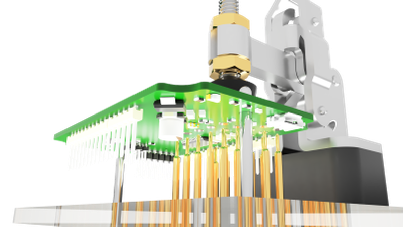
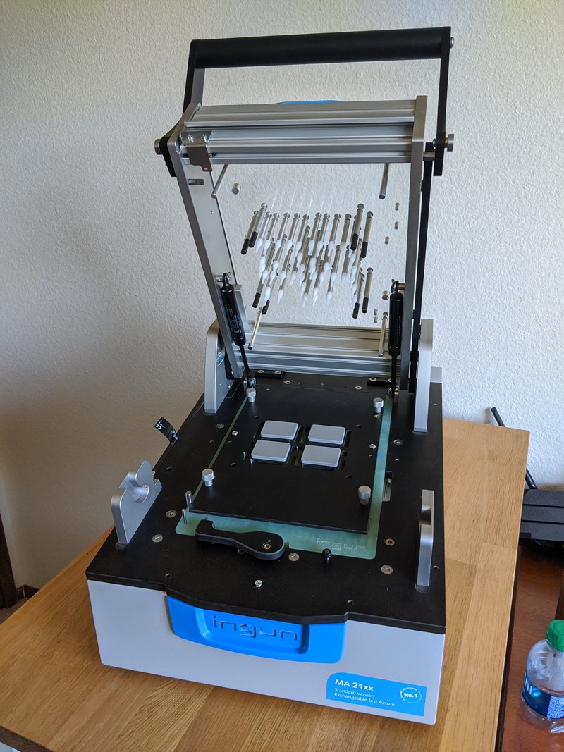
![]() For testing PCB's, we almost always use a Bed of Nails fixture, our favorite fixture bases are from Ingun.
For testing PCB's, we almost always use a Bed of Nails fixture, our favorite fixture bases are from Ingun.
![]()
How do you intercept high speed signals for test (e.g. diff pair, crystal)?
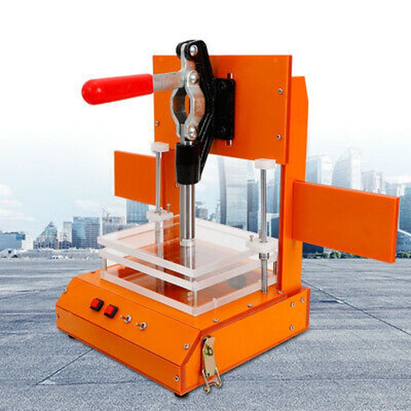
![]() But there are also much lower cost fixtures, like the Aliexpress Bakelite Fixture
But there are also much lower cost fixtures, like the Aliexpress Bakelite Fixture
![]()
![]() Probing high-speed signals can be difficult (looking at your MIPI), but our approach is to typically use standard probes and the shortest signal runs possible within the fixture.
Probing high-speed signals can be difficult (looking at your MIPI), but our approach is to typically use standard probes and the shortest signal runs possible within the fixture.
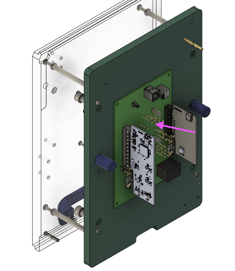
We design a Test Point Carrier Board that solders to the test probe receptacles so that we can route the high-speed signal a short distance to whatever is measuring it.
![]()
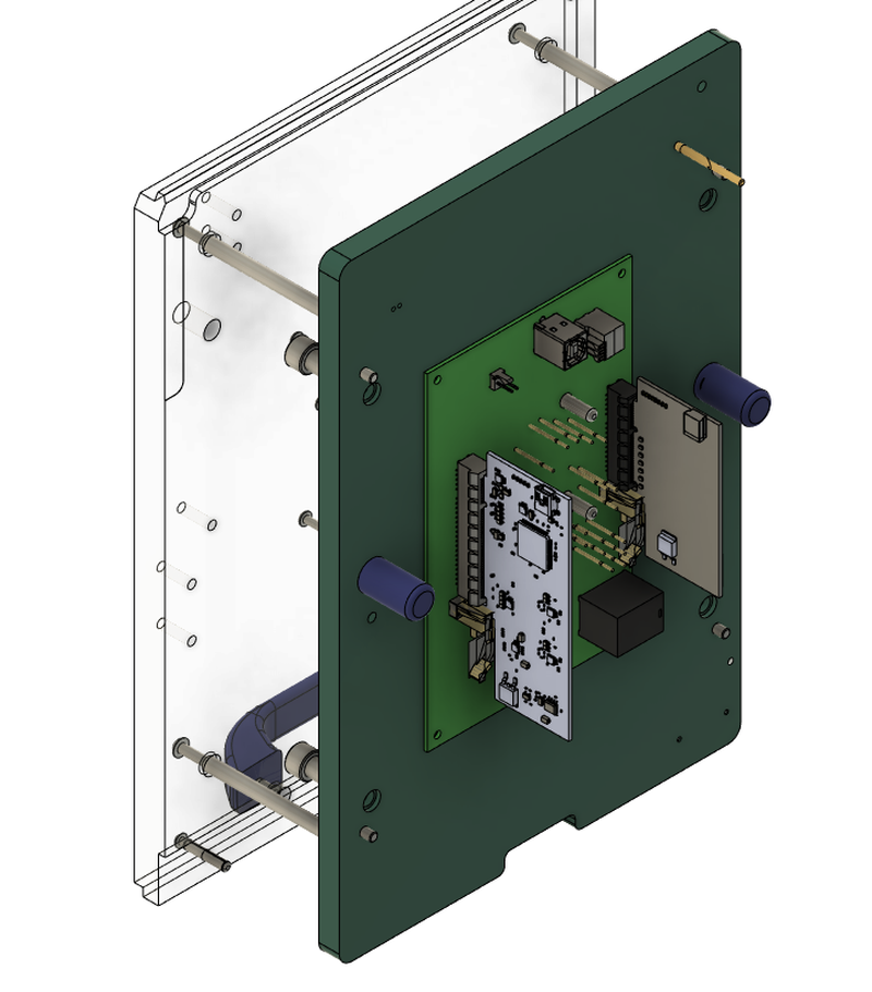
![]() Here's an example of an Ingun test fixture cartridge, the Green Plate is Fiberglass (FR4, same material the circuit boards are made from) and Test Point Carrier Board (TPCB) is mounted below it
Here's an example of an Ingun test fixture cartridge, the Green Plate is Fiberglass (FR4, same material the circuit boards are made from) and Test Point Carrier Board (TPCB) is mounted below it
Cool!
Have you tested audio or other analog outputs on boards before? What was your approach?
![]() I'm planning my first test fixture at the moment. Which brand of test points / pogo pins do you recommend?
I'm planning my first test fixture at the moment. Which brand of test points / pogo pins do you recommend?
![]() Audio is one of those areas where you can as deep as you want in terms of test!
Audio is one of those areas where you can as deep as you want in terms of test!
We've done everything from just using a scope to measure the electrical signal generated from an amp, to using calibrated microphones and audio interfaces to validate hi-fidelity devices
Are those the backs of the pogo pins coming through both boards?
![]() My preferred approach is checking the electrical signal, unless the speaker is part of the PCB assembly
My preferred approach is checking the electrical signal, unless the speaker is part of the PCB assembly
![]() @Friedrich Our favorite probe supplier is Ingun
@Friedrich Our favorite probe supplier is Ingun
 @duncan.lowder Do you make your own KTP and ADP plates(blank with no TP socket holes) or do you source them from INGUN?
![]() https://ingun.com/, and we also use Centalic probes for our Development Fixtures https://centalic.com/
https://ingun.com/, and we also use Centalic probes for our Development Fixtures https://centalic.com/
![]() @skot those are the test probe receptacles, they're a metal sleeve that the spring probe is held by, this allows for the test probes to be easily swapped out when they wear out
@skot those are the test probe receptacles, they're a metal sleeve that the spring probe is held by, this allows for the test probes to be easily swapped out when they wear out
Yeah that makes sense, thanks!
oh, that's genius!
![]() @duncan.lowder Thanks a lot!
@duncan.lowder Thanks a lot!
![]() @Mile We source most parts from Ingun, this makes it really easy for us to machine in 1 operation
@Mile We source most parts from Ingun, this makes it really easy for us to machine in 1 operation
![]() We have also machined our own parts when their lead time is too long.
We have also machined our own parts when their lead time is too long.
Do you by any chance know out of what material ADP plate is made?
![]() We have a Shapeoko and then a Roland MDX50 that we use for most of our machining, we contract out more difficult parts to a local CNC shop.
We have a Shapeoko and then a Roland MDX50 that we use for most of our machining, we contract out more difficult parts to a local CNC shop.
![]() @Mile It's a ESD FR4/G10 material, we've just used standard G10 plate from McMaster or Eplastics
@Mile It's a ESD FR4/G10 material, we've just used standard G10 plate from McMaster or Eplastics
![]() Here's a DFT guide that we have as well
Here's a DFT guide that we have as well
![]()
FixturFab_DFT_Guide_v01 (2).pdf
6 MB
Possibly naive question: are there any standards for laying out PCBs that would make designing test fixtures easier? Like, say, making sure test points land on a 1-mm x 1-mm grid? Seems like that would make it possible to at least design a universal TPCB that could be quickly reconfigured for different boards.
![]() Here are some basics for layout that make it easy to test:
Here are some basics for layout that make it easy to test:
1. Place Test Points on only ONE layer (All on the top or bottom, not both)
2. Place them a grid (1.91mm/75mil is great, 2.54mm/100mil is better)
3. Place Test Points at least 1mm away from other components (farther if the component is tall)
4. Have Mounting Holes and/or Tooling Holes on the PCB to help with locating it
How often do you see "bathtub curve"-type failures, where a board passes testing, but then fails soon after the end user gets it? Do you ever include stress testing?
![]() @Dan Maloney We tried using a "universal" TPCB design, but ended up building some automation that helps us with the TPCB layout (places the receptacle footprints at the correct location) which eliminated the need for a universal design. Especially with how cheap you can get PCBs today.
@Dan Maloney We tried using a "universal" TPCB design, but ended up building some automation that helps us with the TPCB layout (places the receptacle footprints at the correct location) which eliminated the need for a universal design. Especially with how cheap you can get PCBs today.
"Place Test Points on only ONE layer (All on the top or bottom, not both)" -- I feel targeted by that comment Duncan. ;)
![]() @Adam Demuri Depending on the device, doing some "Burn-In" or Stress Testing is key (had some horrible experiences with Motor Driver ICs...)
@Adam Demuri Depending on the device, doing some "Burn-In" or Stress Testing is key (had some horrible experiences with Motor Driver ICs...)
![]() One of the biggest factors with burn-in testing is cycle-time, since it can vastly increase the amount of time needed to test the device. Definitely something to think of when looking into implementing a test like this
One of the biggest factors with burn-in testing is cycle-time, since it can vastly increase the amount of time needed to test the device. Definitely something to think of when looking into implementing a test like this
Yeah, that's definitely a trade-off.
Would you then recommend to separate testing and stress testing?
any pro tips on testing boards with RF; like BLE, WiFi, etc?
![]() @Nicolas Tremblay I'd say yes, you typically want a very fast functional test (may include In-Circuit Testing as well) to verify that the device works correctly, and then dedicated stress-test fixtures that only do the longer stress testing.
@Nicolas Tremblay I'd say yes, you typically want a very fast functional test (may include In-Circuit Testing as well) to verify that the device works correctly, and then dedicated stress-test fixtures that only do the longer stress testing.
![]() @skot We have two approaches:
@skot We have two approaches:
- Cheap and Easy RSSI Testing
Check the RSSI for WiFi and/or BLE to verify signal strength from the device under test (can use a USB WiFi/BLE dongle and some software tools)
Connection tests, verify that the DUT can connect to a WiFi Hot Spot or BLE device
- Signal Integrity
Use Scopes and Network Analyzers to actually measure and verify that you are receiving the expected signal
![]() We typically lean on the RSSI/Connection testing in production
We typically lean on the RSSI/Connection testing in production
 say the device under test has an lcd that maybe displays certain symbols under certain conditions, would you ever use a camera and test for certain things optically?
![]() @anf
@anf
![]() @anfractuosity Definitely! We've used open-cv to test both displays as well as LEDs
@anfractuosity Definitely! We've used open-cv to test both displays as well as LEDs
So does that mean it might make sense to build some kind of wireless capability (BLE/WiFi/etc) into a test jig? Or is it best to just ad hoc that kind of testing rather than integrate it?
neat, cool :)
I've had some luck with the BLED112 USB dongle. it provides a nice python scriptable interface
![]() @anfractuosity Keep in mind ambient light if you ever implement a system like that, factory lighting can cause havoc if you trained your models using images taken in a dark lab...
@anfractuosity Keep in mind ambient light if you ever implement a system like that, factory lighting can cause havoc if you trained your models using images taken in a dark lab...
mm, that's a very good point
![]() @Dan Maloney It definitely makes some sense to build this into the fixture. We still approach it on a case by case basis, but leverage WiFi Access Points and/or USB devices to help with this testing and we will then integrate them within the fixture
@Dan Maloney It definitely makes some sense to build this into the fixture. We still approach it on a case by case basis, but leverage WiFi Access Points and/or USB devices to help with this testing and we will then integrate them within the fixture
Cool. In fact, this all seems so much cooler than testing has a right to be ;-)
similar to the ambient light issue, it always seems like factories are miserable RF environments. make sure to take that into account when you're looking for a specific RSSI

Discussions
Become a Hackaday.io Member
Create an account to leave a comment. Already have an account? Log In.