 Dan Maloney
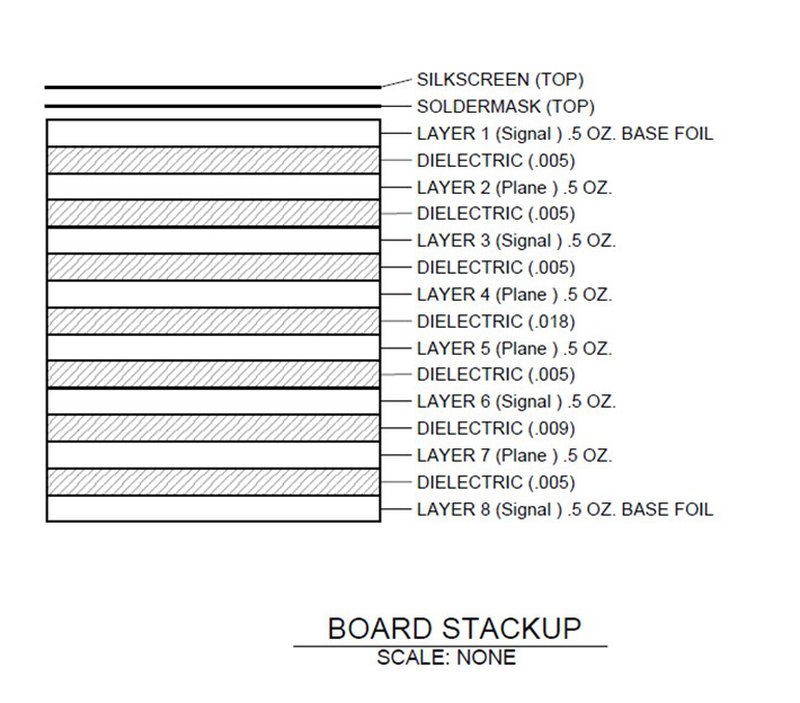
Ok, here is the board stack up
![]() OK, thank you very much.
OK, thank you very much.
Your links are already helping me!
Do you know any surface mountabe heatsinks manufacturers, too?
So far I used some BGA-heat sinks and mounted them to the PCB with some custom made metal frame.
But that is quite labour intensive and complex. A simpler approach would be appreciated (like those "standard" heatsinks with M3-drill holes and a rail for the mounting clips?
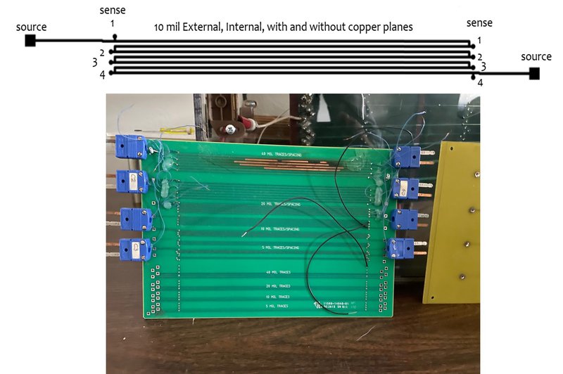
Here is one of the trace configurations on top of the image
It's a serpentine configuration so we would know that same current is in all the traces
Source wires at the beginning and end, along with sense wires at various traces.
We had four copper planes in one configuration and the no traces in the other.
This data has no planes
The board is suspended in air, same as in IPC-2152. We follow the test procedure in IPC-TM-650 2.5.4.1a

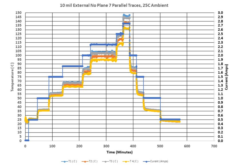
This data is for the board with copper planes.
 That's interesting -- almost like there's two equations to fit the transitions to steady state...
Current is on the right side axis and the blue lines are current.
![]() If I'm understanding this correctly, the current still still only being applied through the layer 1 serpentine 10 mil trace but there is an added electrically isolated plane in the PCB for the second chart?
If I'm understanding this correctly, the current still still only being applied through the layer 1 serpentine 10 mil trace but there is an added electrically isolated plane in the PCB for the second chart?
![]() Why thermocouples and not thermal imaging?
Why thermocouples and not thermal imaging?
I will be adding content back to my website soon at www.thermalman.com. I have already added my papers used to create the charts in IPC-2152.
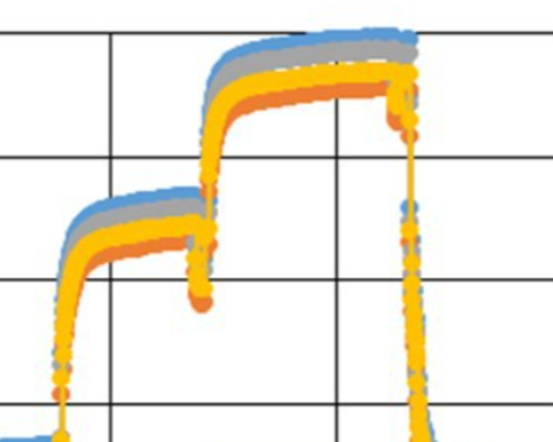
What's happening -- the transition peaks as I'd expect when the current rises. But then as you let it go for a long period of time, the rate of heat transfer looks almost linear.
No thermocouples
![]() Random thought... could the resistivity-temperature dependence of copper be used to employ the traces themselves as temperature sensors? Could be handy for assessing the inaccessible ones in the internal layers of the boards.
Random thought... could the resistivity-temperature dependence of copper be used to employ the traces themselves as temperature sensors? Could be handy for assessing the inaccessible ones in the internal layers of the boards.
The method uses the resistance of the trace.
![]() ...ah!
...ah!
![]() Was confused by the blue connectors on the board.
Was confused by the blue connectors on the board.
 We're at the end of our normally allotted hour now, but it seems like the discussion is still plenty active. I say keep going if you have the time, Mike.
Random thought... could the resistivity-temperature dependence of copper be used to employ the traces themselves as temperature sensors? Could be handy for assessing the inaccessible ones in the internal layers of the boards. Yes, as long as you know the resistance of the trace before heating, then the temperature can be calculated
Hey Mike -- didn't you say you're looking for a company to sponsor your continuation with the work?
I'm looking for a new home for all the software, data, hardware that my company created.
 I frequently find myself with very short power traces. Like < 25mm. I am paranoid about thermals, often ending up in ABS enclosures. I'll tend to throw 3oz and wide AF at everything, but i wonder how much I'm over-compensating
throwing layer after layer of 0.5oz isn't really in the cards for most of the designs I deal with
I join your paranoid feelings about thermals. It was an area of study that I have yet to complete
3oz external 2 layer or 4layer w/ 3oz external / 0.5oz internal is typically all I can get made
![]() "Overcompensating" is an ugly name. Better say "enhanced margins".
"Overcompensating" is an ugly name. Better say "enhanced margins".
I used to design up to 24 layers of 2oz, and didn't have a choice
![]() There's no kill like overkill!
There's no kill like overkill!
I wonder if I have a picture of the baord I soldered square copper stock to....
it had to do 100A
It was never overkill in the designs I worked on.
100 A is a bugger
I gave up on doing it with just the PCB so I sodlered 10mm square copper bar to the PCB for bus bar
![]() Do you have any good rules of thumbs on the thermal capacity of a PCB? I'm usually unsure on how to handle higher current pulses of say a DC motor starting from standstill.
Do you have any good rules of thumbs on the thermal capacity of a PCB? I'm usually unsure on how to handle higher current pulses of say a DC motor starting from standstill.
All about reducing the delta T from Source to sink
what about MCPCB?
![]() Here's a somewhat off topic question: I just saw a big Sun server teardown and they had screwed the device PCB to bus bars coming from the power supplies. I always thought you shouldn't run screws through a PCB because the PCB substrate would "flow" overtime and so the screws would never maintain their pressure. Is that just a myth?
Here's a somewhat off topic question: I just saw a big Sun server teardown and they had screwed the device PCB to bus bars coming from the power supplies. I always thought you shouldn't run screws through a PCB because the PCB substrate would "flow" overtime and so the screws would never maintain their pressure. Is that just a myth?
It's starting to get easier to get
I've seen "single layer" MCPCB as well as metal core 2 layer as well as metal prepreg copper prepreg copper 2layer
Do you have any good rules of thumbs on the thermal capacity of a PCB? I'm usually unsure on how to handle higher current pulses of say a DC motor starting from standstill. I assess the pulse using a lumped parameter representation of the physical geometry. It is discussed in the book we showed earlier from Steinberg
@tinfever If it's a concern for you, you can always include spring washers in your design.
I'd always wanted to get a manufacturer to connect to the metal layer wth vias for thermal transfer but none of the PCB board houses seem to want to do that
@Dave Blundell Yeah -- the copper won't bond. It'll fail after a few thermal cycles.
I was always able to get by with internal copper planes, but I didn't have to deal with 100A in a pcb.
how much heat transfer can you get into the MC layer without connecting thermal vias?
I always wondered about that
evidently, it's a shitload based on the LED lighting designs I see
![]() I haven't had any need to do secure screws through a PCB but that myth always kind of worried me. Those issues where "it might work in the short term but could fail in a year" always concern me because it wouldn't show up in normal testing. A spring washer would make sense though.
I haven't had any need to do secure screws through a PCB but that myth always kind of worried me. Those issues where "it might work in the short term but could fail in a year" always concern me because it wouldn't show up in normal testing. A spring washer would make sense though.
Anyone designing with Lithium ion batteries? If so, account for the power when they are charging as well as discharging. Lesson learned with Mars Orbiter
![]() Here's the video in case anyone was curious:
Here's the video in case anyone was curious:
@tinfever Take a look at the springs used in your motherboard heat sink application. I guess they're probably not called spring-washers. Those are something else.
![]() Great thx
Great thx
![]() @tinfever I have been curious about that too. One variant I have seen is to use vias around the mounting hole as that would prevent flow? Not been able to find anything to back that up with actual testing though
@tinfever I have been curious about that too. One variant I have seen is to use vias around the mounting hole as that would prevent flow? Not been able to find anything to back that up with actual testing though
Well, I think it's time for me to hit the road. There were a few questions that are difficult to answer in this format. i hope I provided some help to those of you that asked questions
![]() Thank you !!!
Thank you !!!
![]() Batteries, yes, do you have a link to the Mars orbiter?
Batteries, yes, do you have a link to the Mars orbiter?
![]() Thanks!
Thanks!
Thanks Mike!
![]() Thanks!
Thanks!
![]() Hmm. Yeah, I wonder if those spring screws provide enough pressure to maintain good electrical contact. I bet NASA has written some papers on the exact subject if I bothered to do any research.
Hmm. Yeah, I wonder if those spring screws provide enough pressure to maintain good electrical contact. I bet NASA has written some papers on the exact subject if I bothered to do any research.
![]() Thanks!
Thanks!
OK, things have slowed down a bit, so I'm going to call time "officially" and say our thanks to Mike for his time today. Feel free to keep the chat going, though -- the Hack Chat is always open.
The lithium batteries were actually on the landers.
Good day all! Cheers!
And thanks to everyone for all the questions. Great discussion today! I'll pull a transcript in a few minutes in case anyone needs to refer back to something.
https://photos.app.goo.gl/rhG8gccedMz1yHE27

New item by Dave B.
Thanks Mike! And thanks to Mark for helping set this up!
that was a prototype from hell
Discussions
Become a Hackaday.io Member
Create an account to leave a comment. Already have an account? Log In.