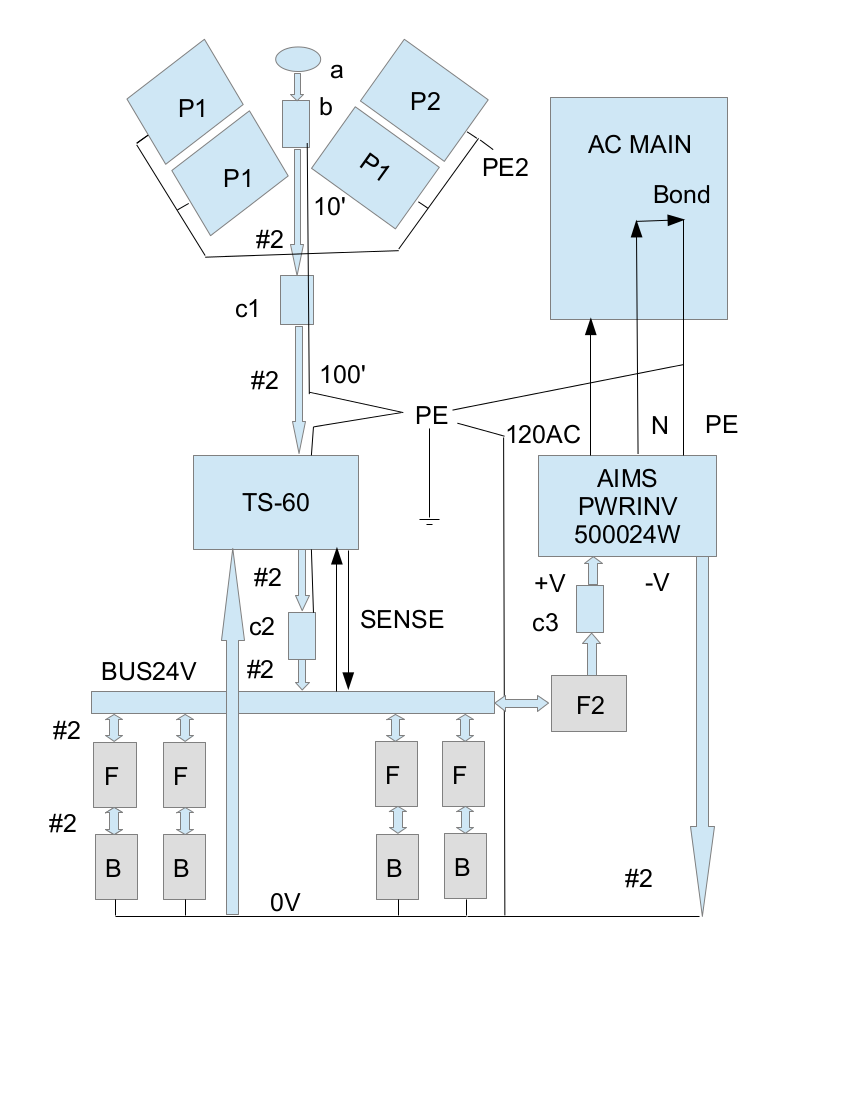
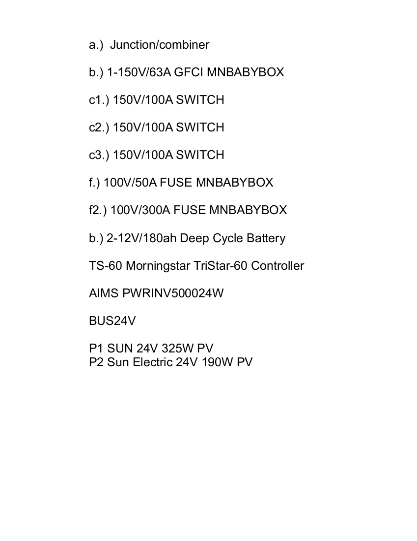
Block Diagram

Three safety disconnects are required. A fuse in series with each 24V battery, as well as a fuse in series with the inverter disconnect switch. Home Depot offers a reasonably priced selection of switches DC rated, usable for this application. Locking is a requirement for the array disconnect, preventing tampering/disconnection. It must be rated for outdoor use. Otherwise, the controller to battery disconnect is inexpensive 30A 2-pole. However switch c3, to disconnect the batteries from the inverter, is ideally rated for 200A. Home Depot offers a suitable 2-pole 100A switch for less than $100. With ratings upward of 100A, switches become expensive. NEC inspection is likely to find these DC-rated switch components acceptable (my system voltage is 28.)
Beyond this, there is requirement for battery interconnection to be of stranded type. I plan to use two MNBABYBOX enclosures. One with the battery fuses. The other at the array with a 150V/63A GCFI breaker. The disconnect switch must be within 10-feet of the array. All switches require labeling.
I plan to use AWG#2 aluminum wherever possible, but may find it optimal to use #6 copper in some places.
All this, and I could decide to put the 28-volt conductor entering my basement into flex steel conduit. After everything, it is a reasonable cost to add this protection, same as required for conductors entering from the well.
It is difficult to decipher everything and filter what is needed for my installation, much of NEC regulation intended for larger, higher voltage installations. It should not be impossible. for me to apply common sense, and then solve compliance issues, one at a time.

 C. Prichard
Discussions
Become a Hackaday.io Member
Create an account to leave a comment. Already have an account? Log In.