Hardware
Since my project is centred around the audible frequency spectrum, I am using "speakers" (sound emitters) and simple microphones.
Transmitters:
- Ultrasound transmitter from SR04. They are cheap and works in the 35-45kHz range.
- Speakers and amplifier from an old gaming-setup I don't use anymore. They can send sound in the audible spectrum from around 50Hz to 18kHz. Actually, it does transmit 30kHz and even 40kHz, but signal is really weak, but not too weak, as my microphones can pick up the signal.
Receivers:
- I use cheap MAX9814 Electret Microphone Amplifier Module. I remove the microphone and use the microphones in an array setup. The amplifier is used to feed sound into my audio interface.
- I have designed a very simple 8-channel PCB that wires power, GND and out to the mini-jack connectors. I can then use the boards in 8 channel configurations. 3x boards = 24 channels.
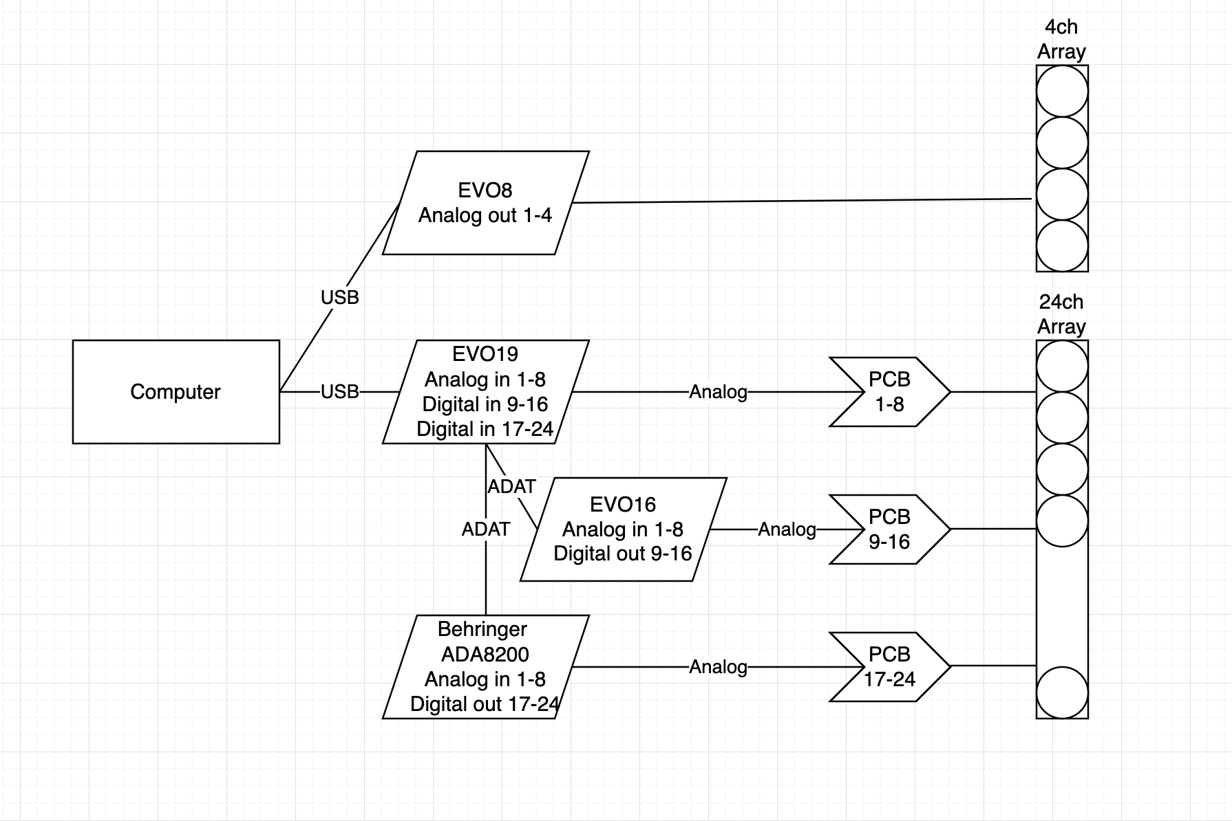
- Audio interface is a bit of a mess. I use two EVO16's, one master and one more as a slave. Each one can record 8 channels. The 3rd is just a Behringer ADA-8200 preamp that sends digital audio via the optical connection to the master EVO16. In total I have 24 channels, if I run at 48kHz sampling. I can do 16 channels at 96kHz sampling rate.
- The master EVO is connected to my computer, where my processing software is running. Processing is computational heavy. My computer has a Nvidia CUDA processor, so I use the CUDA for heavy lifting the FFT's required to beamform.
- At some point, I might replace the expensive audio-interfaces with cheaper analog-digital converters.
- Using professional studio quality ADA's gives me more focus on the arrays. and the software. They are low noise, hum-free, have great software with them and interfaces very nicely with computers audio-interfaces.
The custom PCB was designed, only to help reduce wiring of power, ground and out for each of the MAX9814. Also, the preamp has a gain option that needed a wire. So doing this using wires I would need 4 wires per pre-amp times the number of channels, currently 16 but will 24. Thats almost 100 wires, just for connecting the pre-amp to the sampling units.
Below schematics is handling 8 channels. Output ends in a minijack connector so I can use standard audio cables (high quality) to lead to the sampling units.
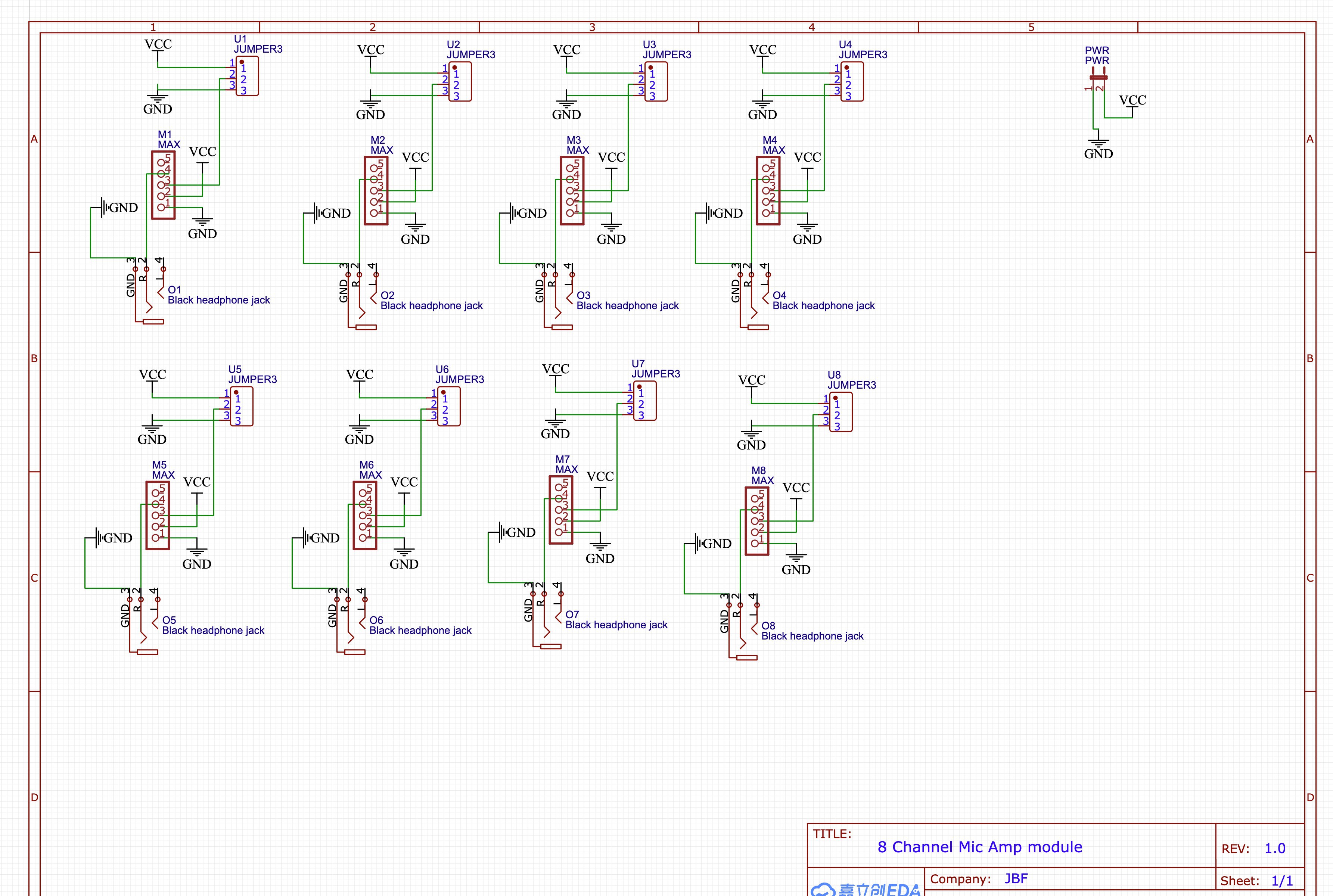
I used EasyEDA service.
- Draw the schematics
- Layout the PCB
- Select components (the minijack connector), jumper connectors
- Order the PCB. Minimum order size i 5. I needed 3 for my project and the remaining two, I used for prototyping and other experiments.
5 days after I submitted my schematics, I received it by currier
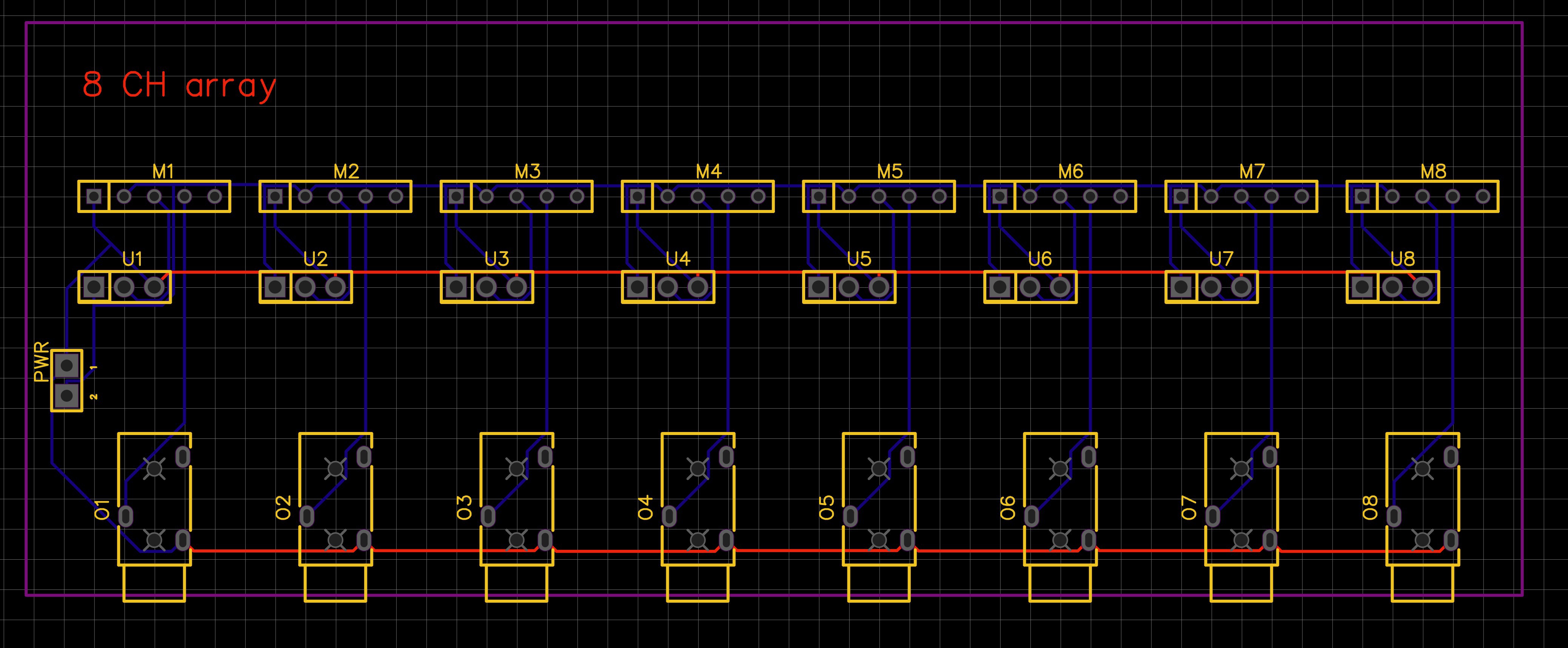
PCB layout.
Assembled 8 channel receiver.

The pins on top of the pre-amps are for connecting the microphone arrays. This way, microphone arrays can easily be swapped around.
Audio interfaces and connection to computer
Discussions
Become a Hackaday.io Member
Create an account to leave a comment. Already have an account? Log In.