Part one. Basic functionality
If you drive a car, it's very likely that you've come across an uncomfortable situation involving a cyclist at least once or twice in your life. Bikes can be quite unpredictable on the road and you often have to guess what maneuver they'll pull next. Electrically-powered bicycles and scooters are especially erratic when it comes to sharing the road. And once it gets dark out, the situation worsens twofold.
Recently, I started dabbling in electric biking myself. However, I would say that factory reflectors on it aren't the best way to make your electric steed easily noticeable on a bike path. Therefore, it's time to unholster my trusty soldering iron and make this world brighter put together some LED turn signals.
I really like the dynamic LED turn signals that come pre-installed on some modern cars. I wish I had something like that on my bike. The most obvious solution would be to use an Arduino and LEDs with a WS2812 chip. Nowadays you can find a microcontroller with its own firmware in something as mundane as a teapot and no one would be surprised by it. However, the fact that this can be realized by just using some "hard" logic and without a microcontroller can really leave some modern electronics engineers scratching their collective heads. Unsurprisingly, that's exactly what I found myself doing when I came across the "RF74xxID The Multifunction Passive 7400 RFID Tag" project on the interwebs.
At the time I was so absorbed by microcontrollers that I didn't even think about the fact that just a couple of decades ago, electronics engineers somehow managed to get by without them, and even launched rockets into space.
Anyway, at some point this became an obsession for me, and I decided to design a dynamic turn indicator circuit using only 7400-series integrated circuit. And with that, I welcome you to dive a little bit into retro electronics with me.
The proposed dynamic turn indicator control circuit doesn't involve any expensive or scarce components. It's easy to reproduce and it works immediately after assembly (if everything is soldered properly).
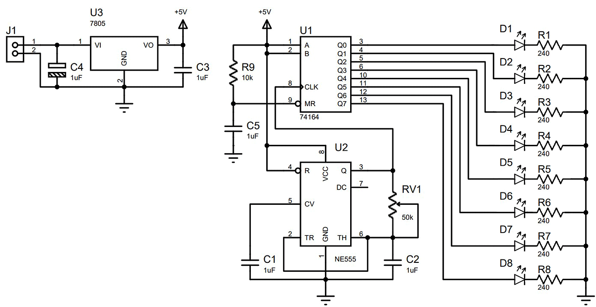
The circuit lights the LEDs in a strip one by one immediately after the power supply voltage is applied to the J1 connector. Once all the LEDs are lit, they will continue to stay lit as long as the power supply voltage is present. If you power this circuit from a car turn signal relay, you get a dynamic turn signal effect as a result.
The speed at which the LEDs in the strip gradually light up is set with the RV1 variable resistor at 50kΩ. Thus, you can pick a speed that's to your liking. At the maximum resistance of the variable resistor, all 8 LEDs will light up in about 0.6 seconds after power is applied. You can choose a position for the resistor that makes all the LEDs stay lit for a little bit after the strip is fully powered, but that's up to you.
If your turn signal relay flashes once per second, you can replace the RV1 variable resistor with a regular 43kΩ resistor.
The standards for rear turn signals are a bit of a mess right now. On some cars they're red, while others have yellow ones. Therefore, the selected R1-R8 resistors are for red and yellow LEDs with an operating voltage drop of about 2.2V. The operating current should be about 10mA. But remember that the maximum output current for the 74HC164 per output is 25mA. This value should not be exceeded. Choose whichever turn signal color you like more.
If you believe that 8 LEDs are too many for your liking, you can reduce their number down from the bottom to the top, i.e. first remove D8, then D7, and so on until you have the desirable number of LEDs left.
Conversely, if 8 LEDs aren't enough, you can safely scale this circuit without any problems or catastrophic price spikes. All you need to do is add the necessary number of shift registers, as shown in the following diagram.
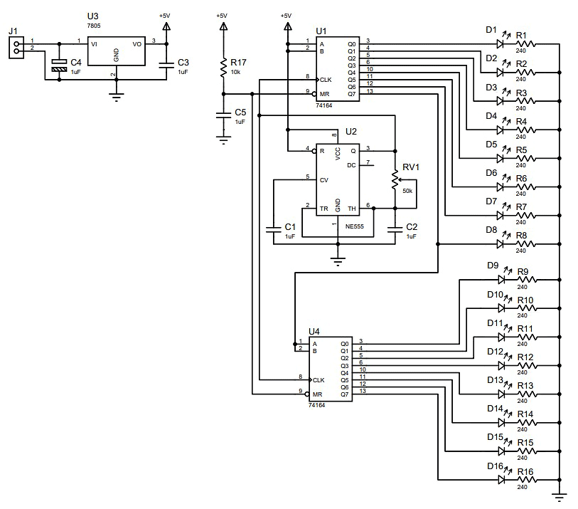
The high output of the first shift register is connected to the data input of the second register. You can also connect the data input of the third register from the high output of the second register. Then you can just keep going with this chain pretty much endlessly.
When adding another circuit, you should immediately add a trim resistor with a lower resistance. I recommend using 20kΩ.
Now let's talk a little bit about powering the circuit. The 7805 voltage regulator allows you to get +5V to power the circuit. The input voltage can vary from +7.5V to 15V. But don't forget that the 7805 can heat up quite a bit, in which case you should use it with a heat sink. The 7805, like any other radio component, also has an operating current limit. Take this into account when selecting the operating current for the LEDs. The total simultaneous current consumption of all the LEDs must not exceed the maximum operating current of the voltage regulator. It would be even better to have a safety margin of about 20 percent.
Do not use this circuit to modify a car! Personally, I'm against modifying cars from their factory state. But you can very well implement this circuit on something like a children's electric car, for example.
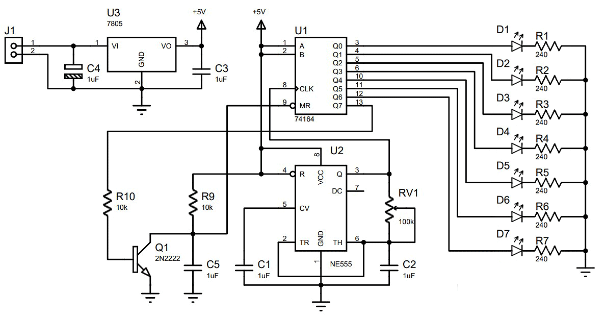
If you really want to use this circuit to modify a bicycle or kid's electric car, a turn signal relay is not an absolutely essential component. The circuit can flash on its own as long as there's a supply voltage. For this, all you need to do is connect a transistor instead of the D8 LED. The Q1 transistor will reset the outputs of the shift register after all the lights are activated. For this setup, I recommend using an RV1 variable resistor with a resistance of 100kΩ.
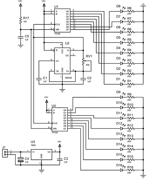
If you cross the first two circuits and replace the yellow LEDs with red ones, you get a dynamic brake light. You could simply connect the second strip of LEDs in parallel to the first one, but it is better to use a second circuit board. Firstly, it won't overload the current outputs of the shift registers, and secondly, it will be much easier to trace the board in the form of a narrow strip.
Part two. Cool device :)
Even at the design phase of the previous dynamic turn indicator circuit, I realized that its functionality wasn't enough for me. I decided to pack both the right and left turn signal functions into a single strip of LEDs. The dynamic way in which LEDs light up is very good at indicating my intended turn direction. I also decided to add some functionality to the circuit to allow for a "sidelight/parking light" mode.
I don't usually ride very fast, so I thought that having brake lights seemed excessive. Besides, it would mean that I have to add additional sensors and wires to the system.
The "challenge" is also supplemented by some rather strict conditions. The device must be built around eight 5050 RGB LEDs which will dynamically light up to indicate right and left turns, and it has to include a parking light/sidelights mode. An important condition was that the circuit had to be made on a single-sided printed circuit board with the LEDs placed in the center of the board.
In the end, I formulated the following requirements for the circuit's functionality:
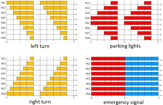
1. When power is supplied, the parking light/sidelight mode is immediately activated. The indication is performed by switching on the red LEDs. The switching intervals of the LEDs have equal values and the total repetition rate is about 1Hz.
2. The turn signals are activated by closing the "Button_Left" and "Button_Right" contacts with the common wire, i.e. closing the common wire with the "Button_Left" contact for a left turn indication and with the "Button_Right" contact to indicate a right turn. The indication is performed by simultaneously switching on the red and green LEDs. The switching intervals of the LEDs also have equal values, with a total repetition rate of about 1Hz.
Simultaneously closing the "Button_Left" and "Button_Right" contacts with the common wire is an unacceptable combination and is mechanically prohibited by the design of the bike's handlebar buttons.
3. To prevent the blue diodes of the RGB LEDs from being neglected, I decided to add an emergency signal to the circuit. But that idea came to me a little later. I only implemented it in the second version of the board.
The emergency signal mode is activated when the "Button_Strobe" contact is closed with the common wire of the circuit. The indication should be performed by alternately switching on the red and blue LEDs. The switching intervals should also be approximately 1Hz.
The previous turn signal circuit was realized using a shift register. It only had the function of indicating a turn in a single direction. But now I need to have the same dynamic lighting effect, but to show turns in either direction using the same strip of LEDs. However, doing this with shift registers and a diode matrix seemed like overkill even to me. But there had to be some kind of special feature in the circuit.
The basis of the circuit is a block of comparators, which control a line of 8 LEDs. The comparator compares the linear rising voltage from the LRVG (Linear-Ramp Voltage Generator) with the reference voltage from the RVS (Reference Voltage Source) also known simply as a voltage reference. The RVS generates 8 trigger thresholds to control each individual LED. The LED control scenario depends on how the control logic switches the RVS.
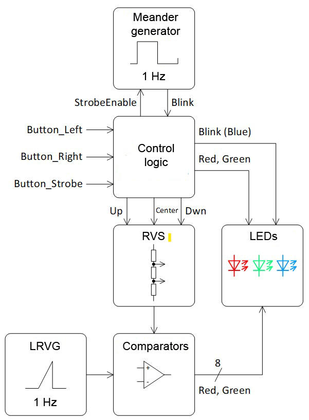
The RVS is a voltage divider made with resistors. There are voltage leads between the resistors that connect to the inverting inputs of the comparators. The voltage divider also has three special lines: "Up", "Center", and "Dwn". The reference voltages at the comparator inputs can change depending on how these lines are connected to the power circuits.The control logic can switch the RVS in the following ways:1. The "Center" line is disconnected from the power supply circuits, the "Up" line is connected to the positive power supply, and the "Dwn" line is connected to the common wire. With this switching scenario, the voltage at the outputs of the voltage divider increases from the lower "Dwn" lead to the upper "Up" lead. This corresponds to switching the LEDs to the left turn mode.2. The "Center" line is disconnected from the power supply circuits, the "Up" line is connected to the common wire, and the "Dwn" line is connected to the positive power supply. In this case the voltage at the outputs of the divider will be distributed in the opposite manner: maximum voltage on the lower "Dwn" lead, minimum voltage on the upper "Up" lead, and the voltage will decrease from the lower to the upper lead. This corresponds to switching the LEDs to the right turn mode.3. To control the LEDs so that they are in the parking light mode, the "Center" line connects the center of the voltage divider to the positive power supply, and the "Up" and "Down" lines are connected simultaneously to the common wire. This divides the voltage divider into two halves, and the reference voltage will decrease from the center to the upper and lower leads of the divider.4. In the emergency signal mode, the "Center" line is also disconnected. Meanwhile, the "Up" and "Down" lines are simultaneously connected to the positive power supply or to the common wire. If a connection is made to the positive power supply, the positive power appears on all the leads of the voltage divider at once, and the outputs of all the comparators will be open at the same time. If "Up" and "Dwn" lines are connected to the common wire, the outputs of all the comparators will be simultaneously closed.The first version of the circuit turned out to be even simpler than I could have imagined. I double- and triple-checked the circuit several times in the simulator and analyzed it empirically. According to my estimation, everything should work. However, this circuit didn't make it to the prototyping stage.
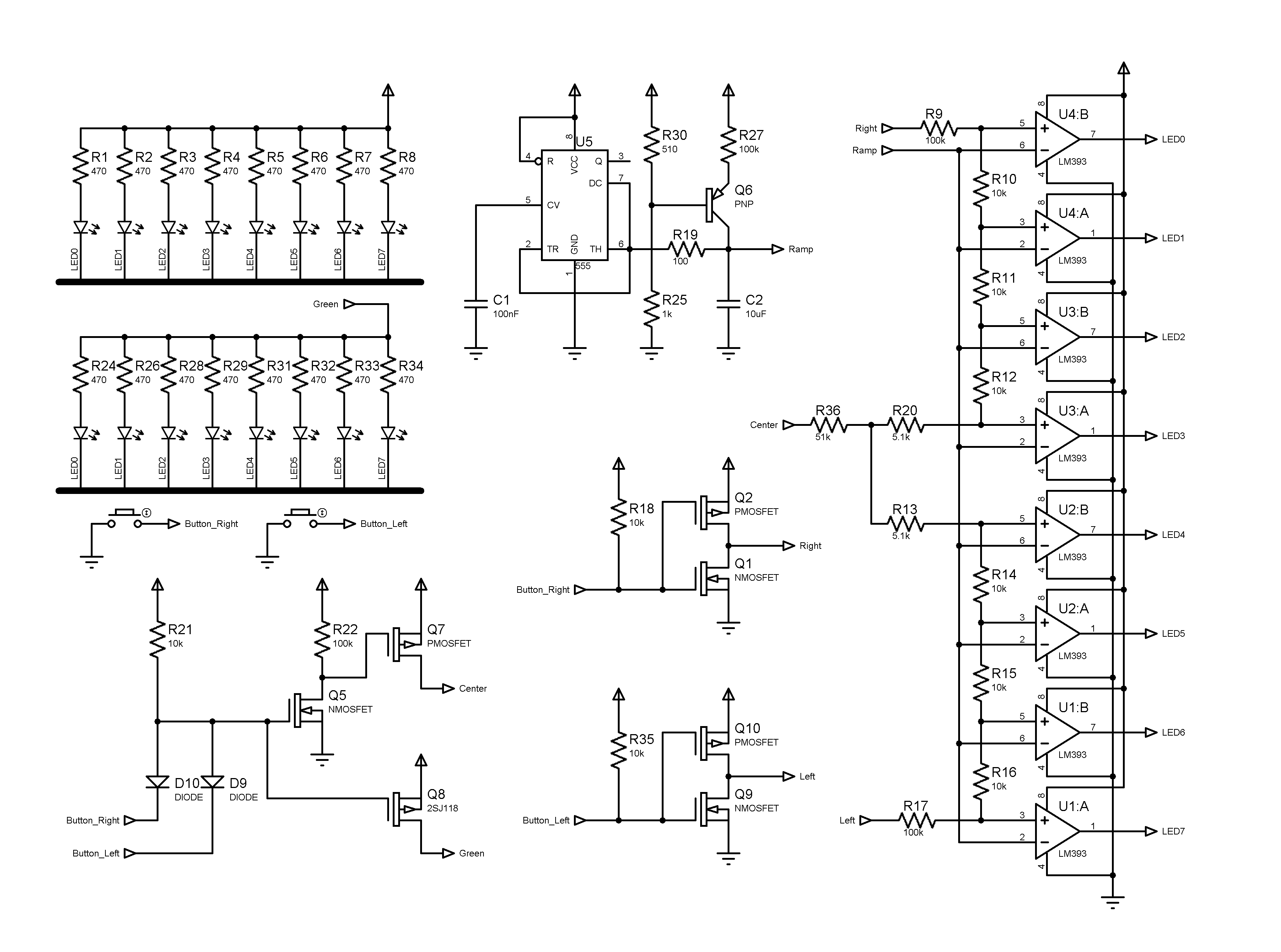
To facilitate installation to the bike, the right and left turn buttons are closed to ground. There is an OR circuit on the D9D10 diodes and the R21 resistor. The Q5 transistor inverts the button signal to control the Q7 transistor. The Q7 transistor closes when either button is closed and disconnects the "Center" lead from the positive power supply. At the same time, one of the half-bridges (Q1Q2 or Q9Q10) diverts its side of the voltage divider to the positive power supply. The other side remains diverted to ground.
The NE555 timer generates the sawtooth pulses. The Q6 transistor provides a linear charge to the C2 capacitor. The C2 capacitor is charged to 2/3 of the supply voltage. Then the timer switches and the capacitor is discharged through the R19 resistor. The resistor limits the discharge current of the capacitor. This also allows the timer to trip when C2 discharges to 1/3 of the supply voltage. Thus, the sawtooth pulse has a range of 1/3 to 2/3 of the supply and has a rising shape.
The R9, R17, and R36 resistors have a higher resistance than the other elements of the voltage divider reference. This is necessary so that the divider's voltages are in the same range as the sawtooth pulses.
The complete circuit differs from the previous one in that it has slightly more complex logic for controlling the LEDs. I decided not to mess around and make it on CD4000 series logic chips. Compared to the 74NS00 series, the CD4000 has an extended supply voltage range. Thus, the circuit works from 2.7V to 9V.
Another NE555 oscillator has been added to the circuit for the emergency signal mode. Its pulses determine the timing of the red and blue flashes. The rest of the circuit works in the same way as the previous one.
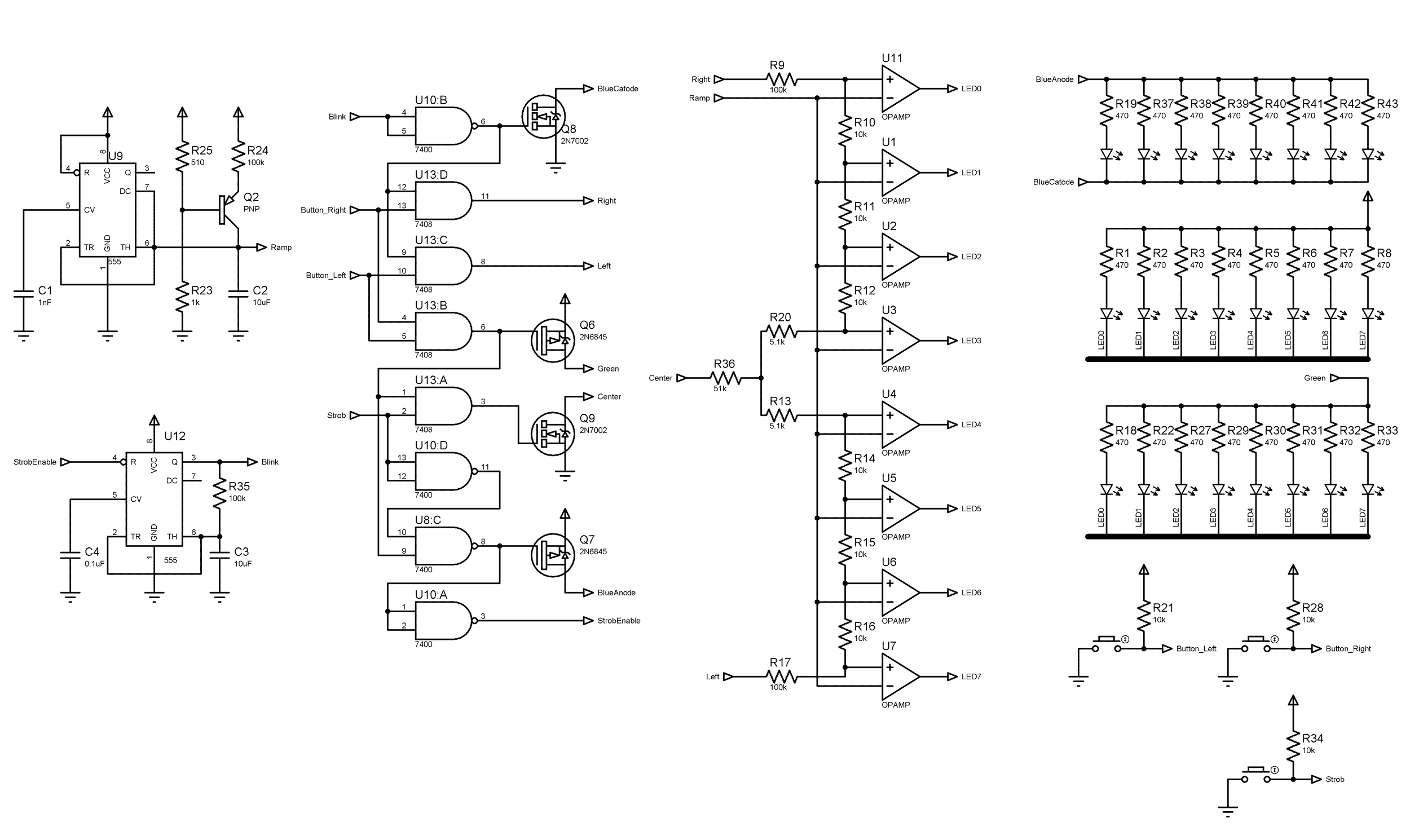
I once again double-checked everything. The circuit turned to be incredibly simple, which is probably why I continued to doubt up to the very last moment that it would work when put to the hardware. With the help of an iron, I quickly assembled the prototype and everything worked as it was supposed to on the first try.
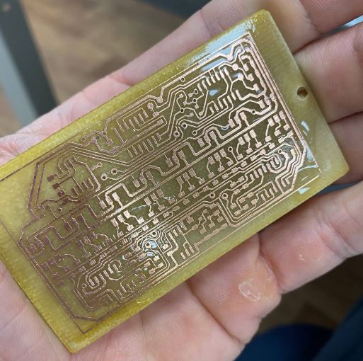
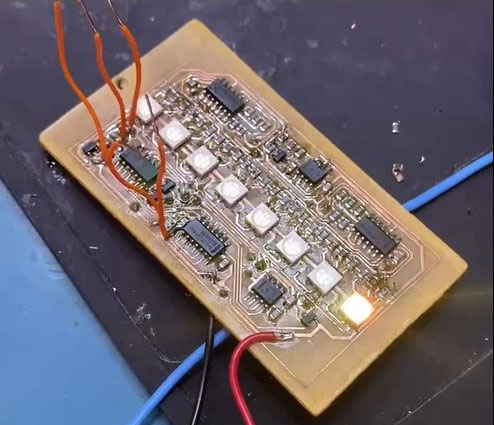
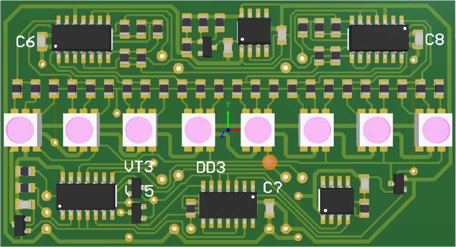
The board looked excellent when it was printed in green! All it took was six simple microchips and a handful of passive components, and there you go – another puzzle is solved.
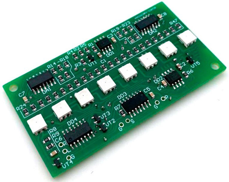
The results of the work can be found in the video.
 teardownit
Discussions
Become a Hackaday.io Member
Create an account to leave a comment. Already have an account? Log In.