 teardownit
Measurement description
I measured the LED chips' temperature and the strip base hanging in the air in the last experiment. Now i simulated mounting the strip under the cabinet in a groove ½" deep.
- At the bottom of the groove. Direct contact between the LED strip and the chipboard. Without an optical diffuser.
- At the bottom of the groove. Direct contact between the LED strip and the chipboard. Additionally, i install a diffuser. The diffuser/shield closes the ambient air access and blocks the heat dissipation from the LED chips through the air. I do the temperature measurement immediately after removing the diffuser to access the measuring device.
Test bench and measuring instruments
I created a special test bench.
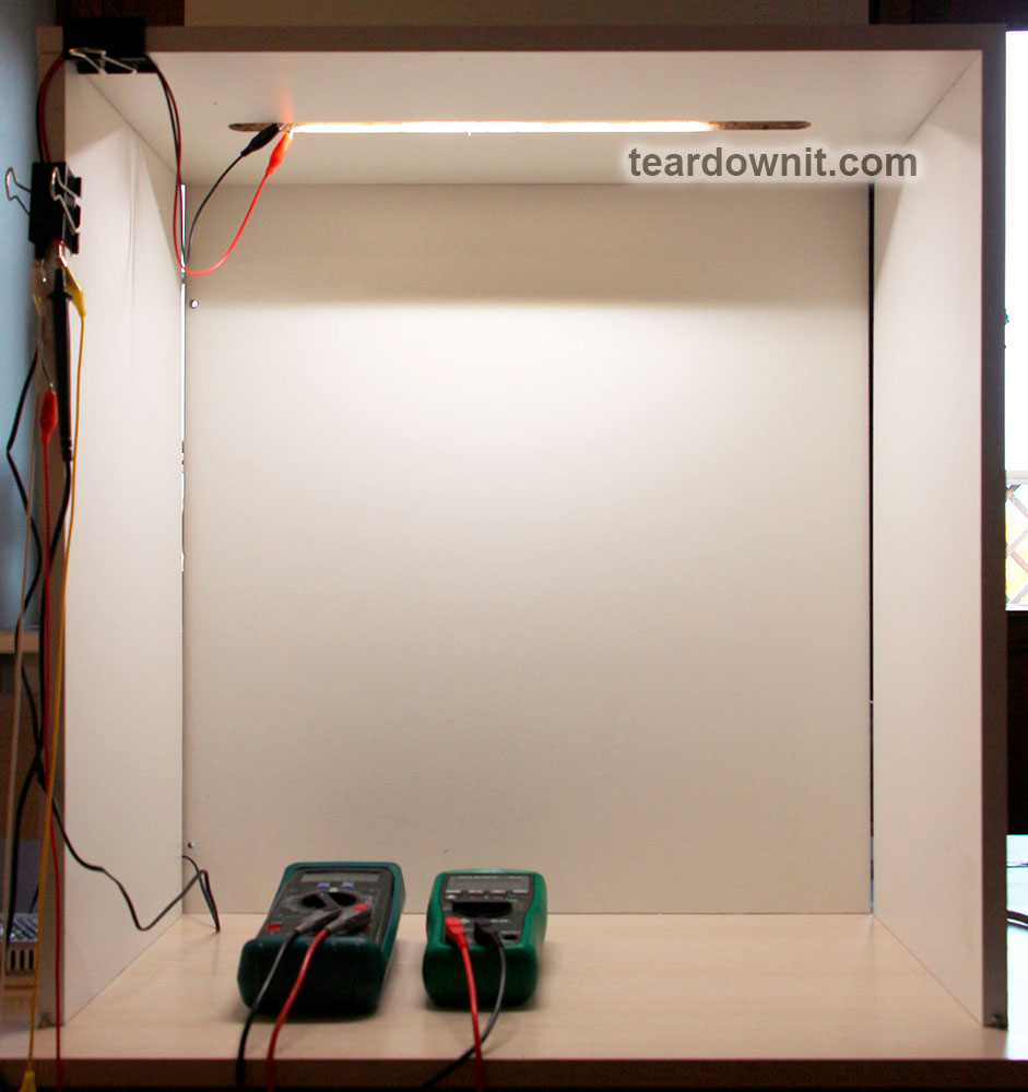
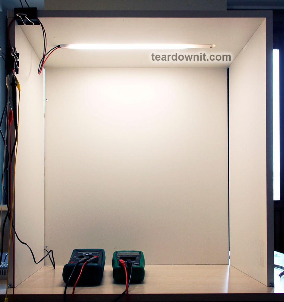
I measured the temperature of each sample after 30 minutes of operation. During this time, the LED strip is fully warmed up and its temperature stabilizes.

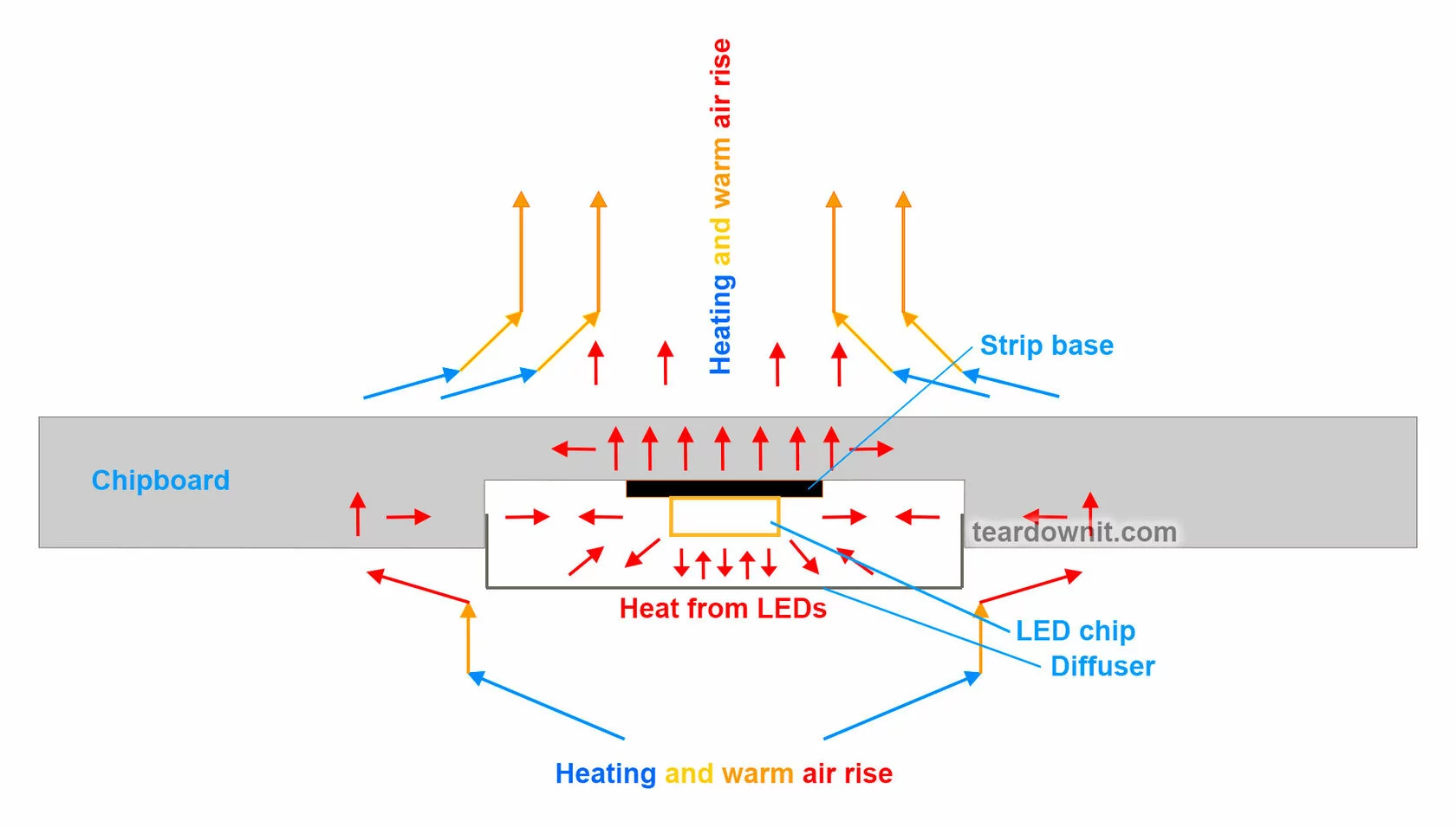
I make sure that the 24V power supply voltage remains constant and i measure the temperature of the LED strip chips in a room with an air temperature of 73 °F.
I use a professional Fluke TiS65 thermal imager (accuracy for temperatures 80-160 °F < 3 °F).
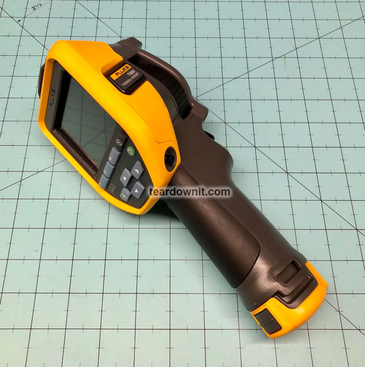
Fluke TiS65
This device records the temperature of the hottest chips in the central part of the field of view.
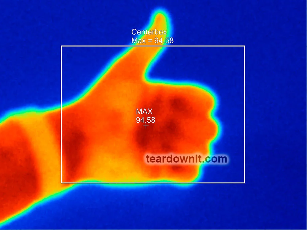
I also record the heating of the chipboard on the back side. I evaluate the effects of the chipboard's thermal conductivity and the danger of heat to objects inside the cabinet.
Results of chip temperature measurements of LED strips on chipboard
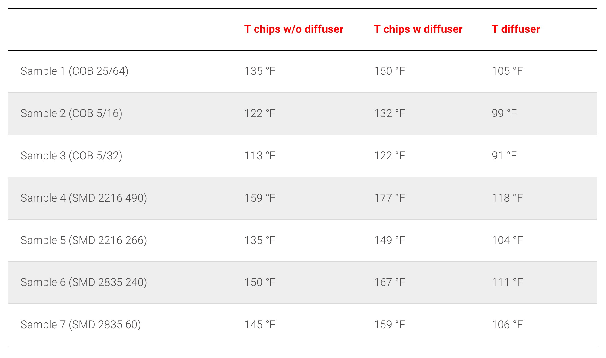
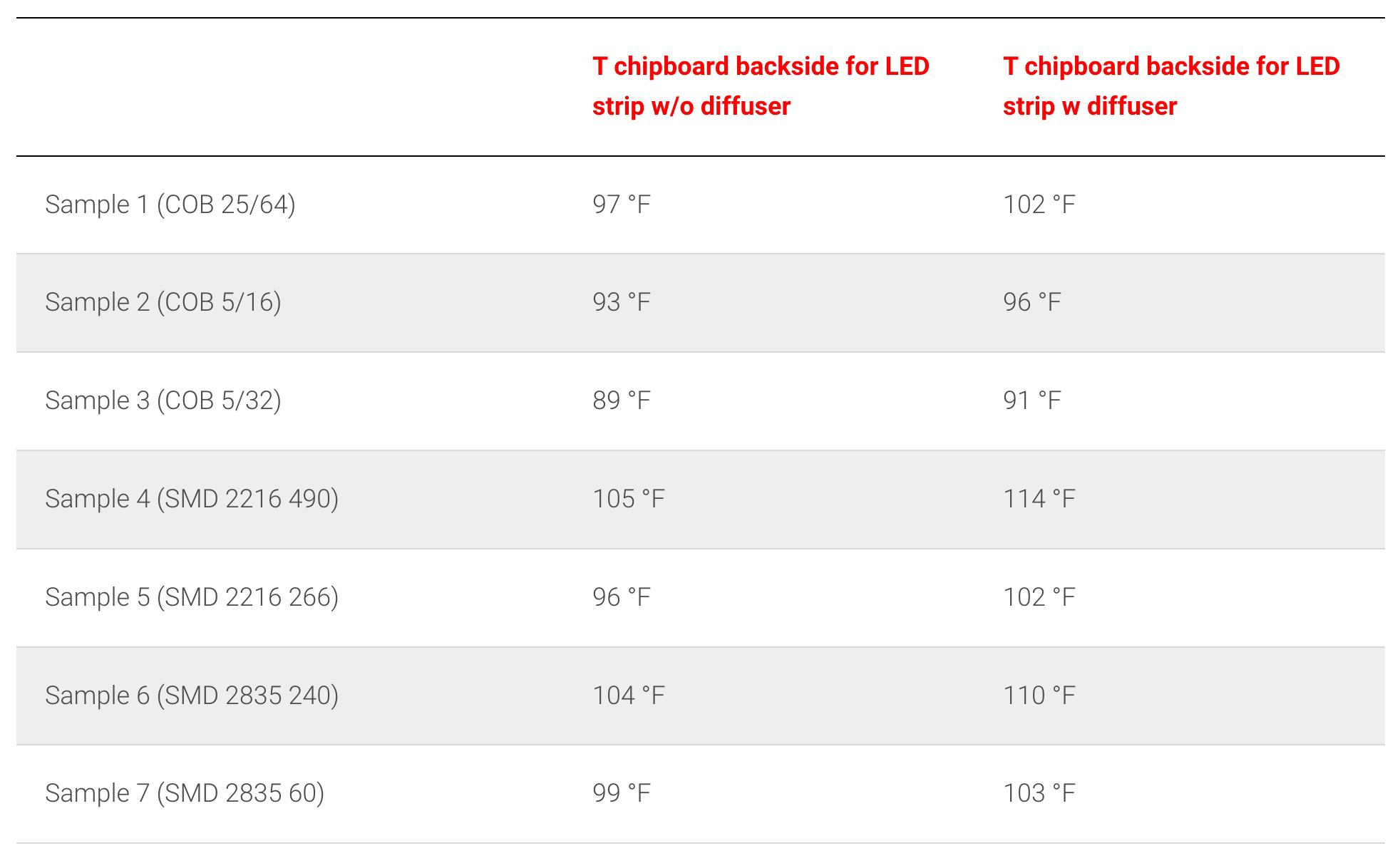
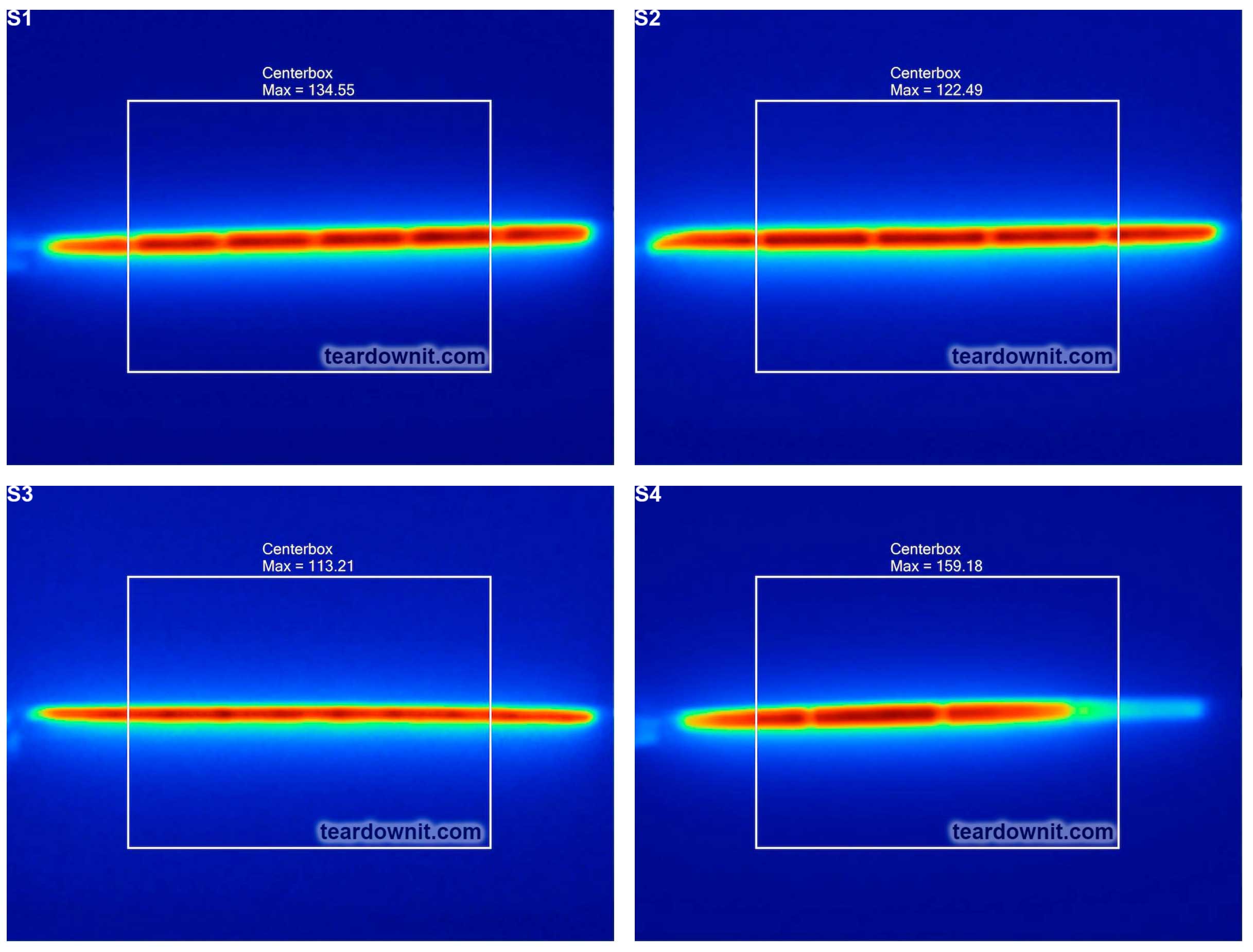
THERMAL IMAGES. LED CHIPS ON CHIPBOARD WITHOUT THE DIFFUSER
THERMAL IMAGES. LED CHIPS ON CHIPBOARD WITH DIFFUSER
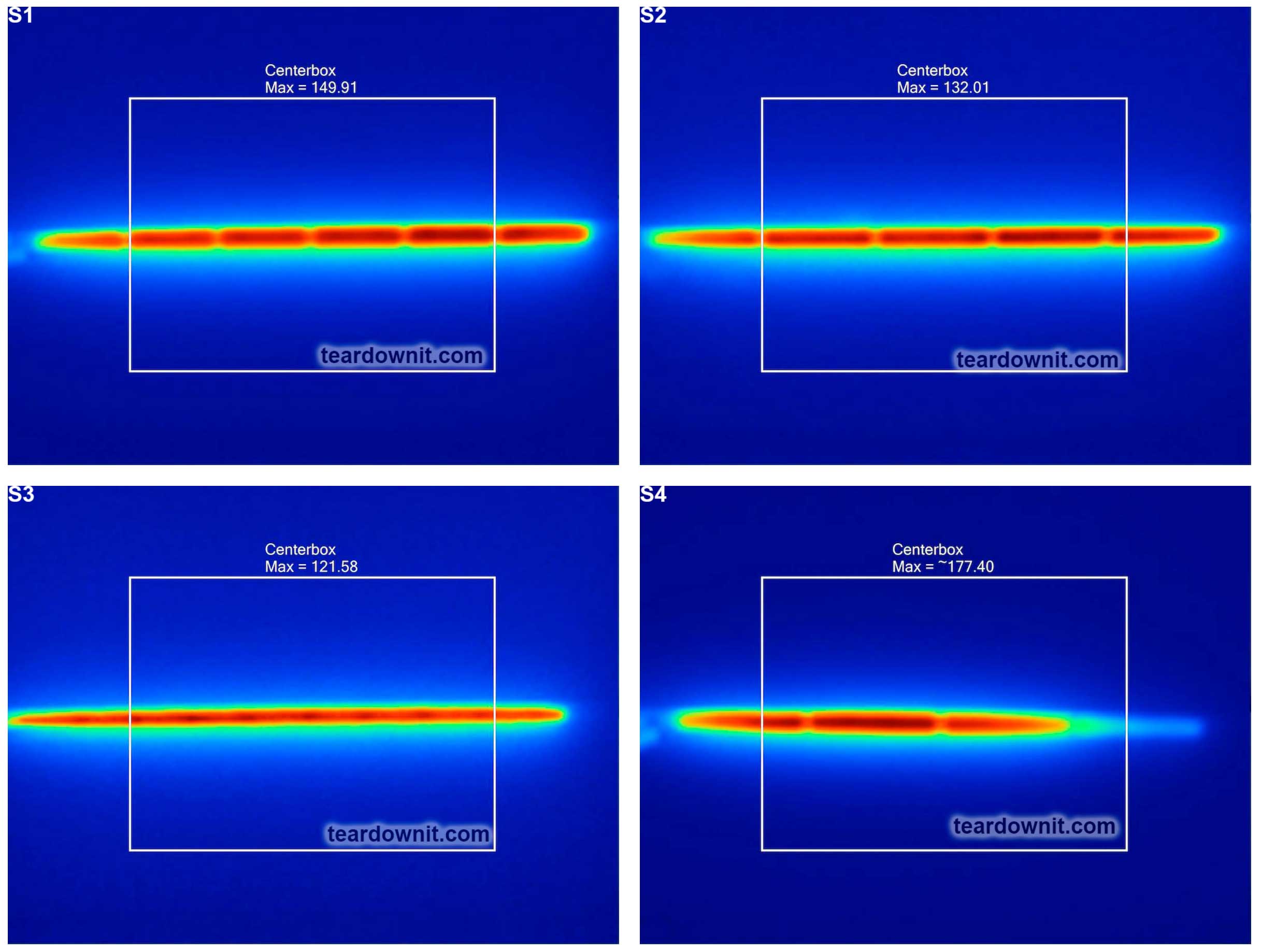
THERMAL IMAGES. DIFFUSER OUTSIDE
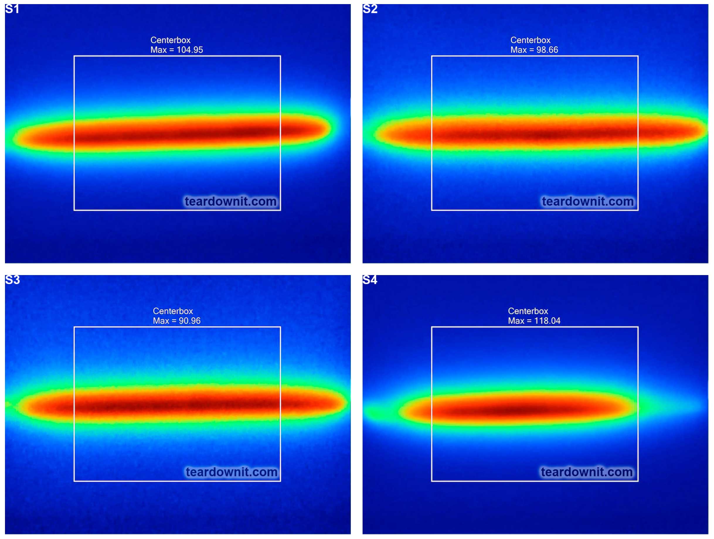
THERMAL IMAGES. CHIPBOARD BACKSIDE WITH LED STRIP WITHOUT A DIFFUSER
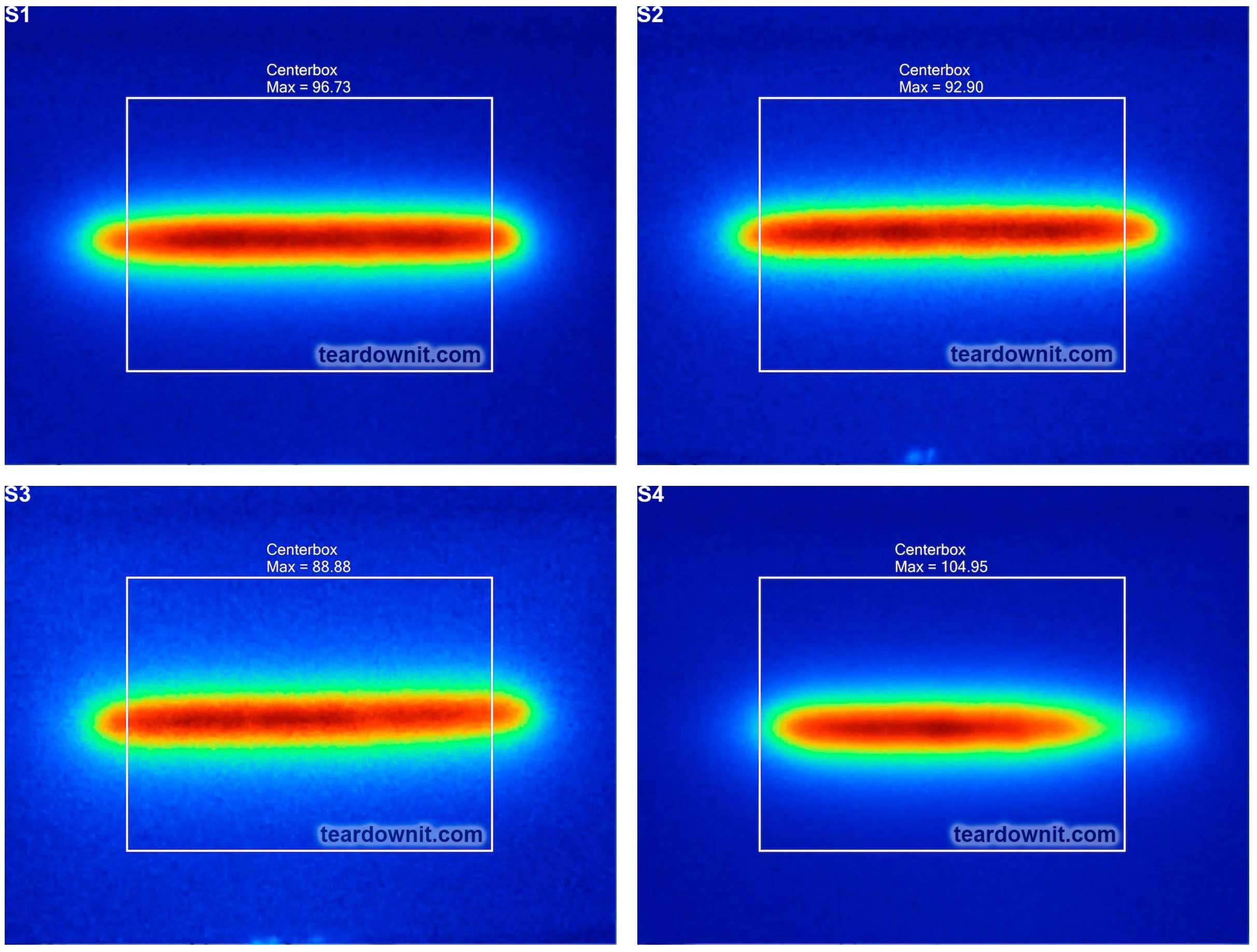
Discussions
Become a Hackaday.io Member
Create an account to leave a comment. Already have an account? Log In.