 oshpark
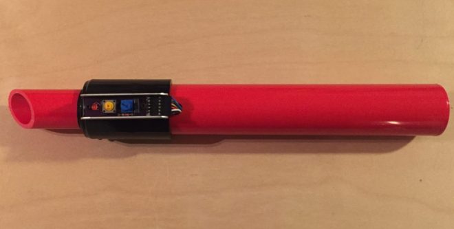
Carlos Vadillo and Bx Dawes created the GlowSaber project to help kids in Alameda learn about physics, engineering and programming:

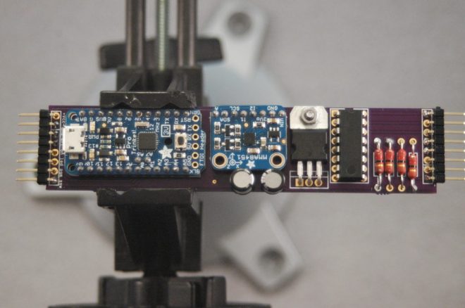
Building the GlowSaber main board
All the logic, sound and light effects of the GlowSaber are performed by a small microprocessor board. In this tutorial I will explain, step by step how to put together the main board of a GlowSaber.
One premise that I had while designing the GlowSaber was that I should be able to build all of it with tools that I already have. That limited the materials I could choose to those that I could cut, drill and glue with just the basic tools:
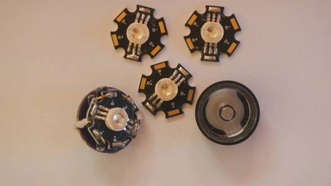
The GlowSaber uses a Vollong 3 watts RGB LED. It is very bright and more than enough to light the length of the blade. When designing the GlowSaber I found that I needed a way to connect the LED to the main PCB and I designed a LED break out
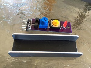
How to use a potentiometer to change the behavior
The GlowSaber has a switch assembly, that controls the on/off functions. It also has a LED to show that the GlowSaber is ready to start, and finally has a small 1 kΩ potentiometer. The following is a schematic of the switch assembly:
cvadillo has shared the board on OSH Park:
GlowSaber
![]()
Discussions
Become a Hackaday.io Member
Create an account to leave a comment. Already have an account? Log In.