I recent acquired some Audio Voltmeters that we're going to be throw out. One was working and one was going nuts, so I had a tinker prior to attempting to repair. I tried looking for some user manuals, but got no where without signing my life away on old.dodgy looking sites.
Figuring out how it works
Overview
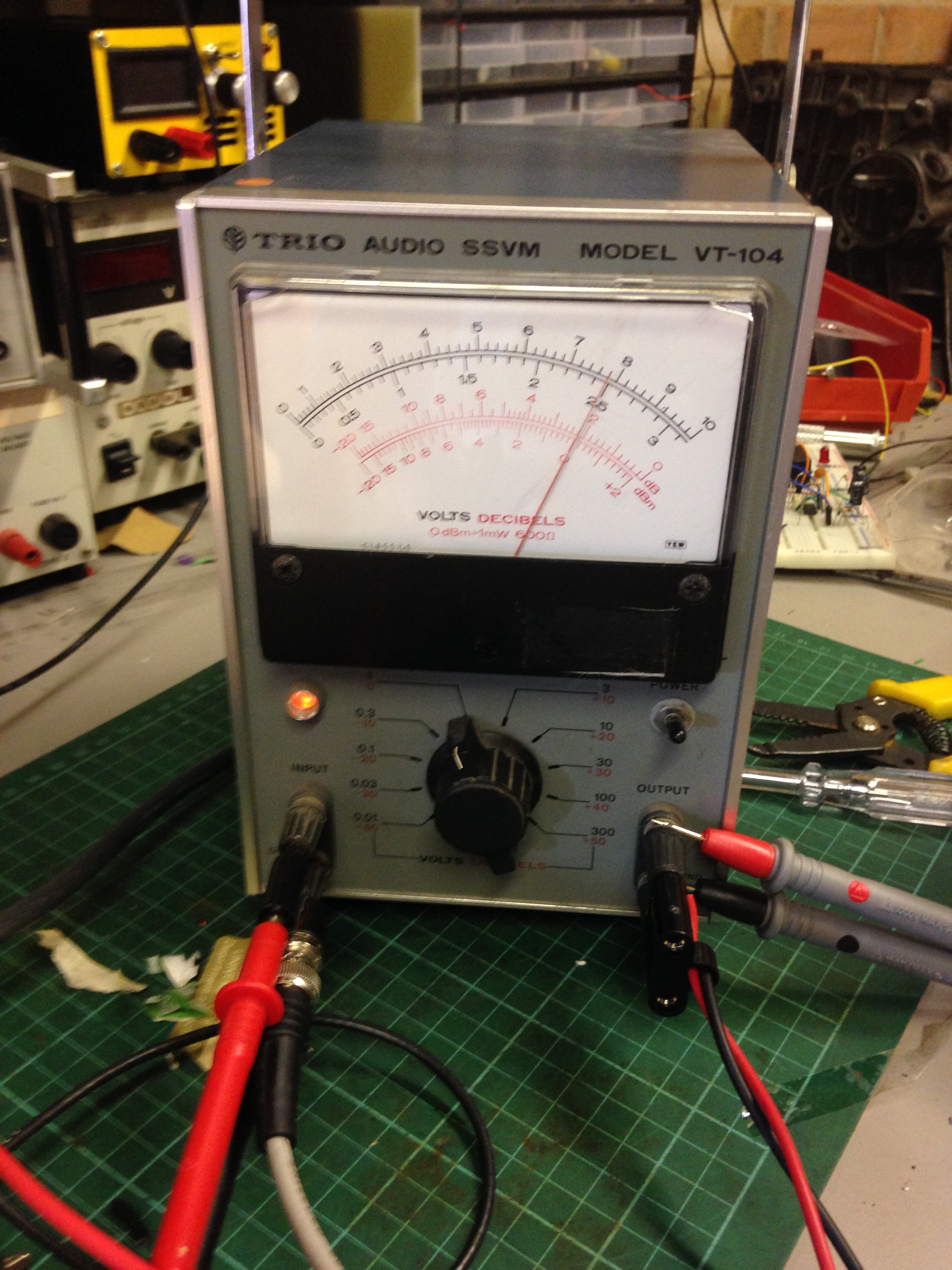
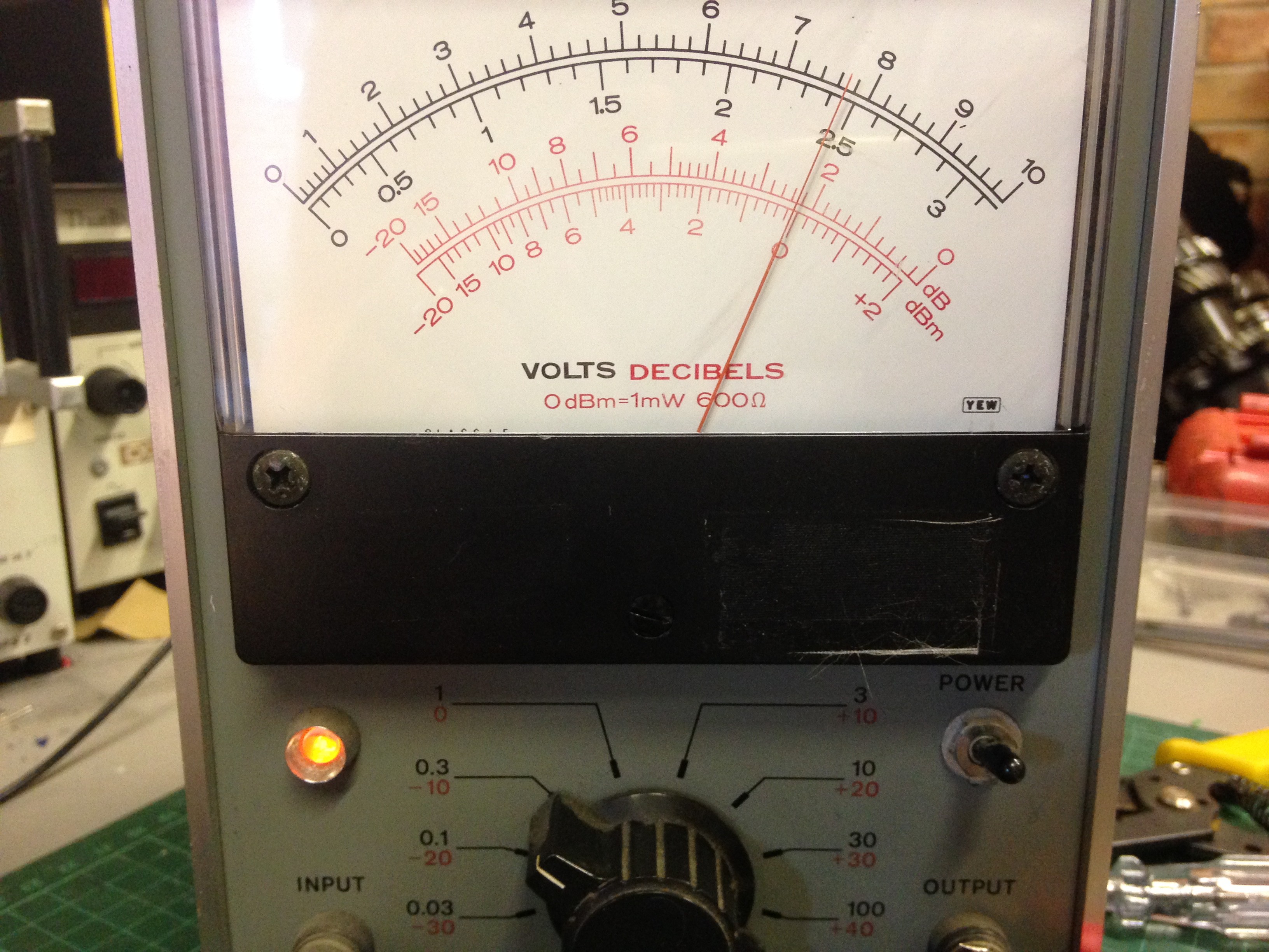
As can be seen: there's an input, an output, a range know and a power switch. The readings on the scale are Volts (dual range: 0-10V and 0-3V) and another scale in red has dB and dBm.
What is dBm
dBm is a measurment of power with respect to 1mW. Like with measuring gain in Decibels, except it is not with respect to the input power, but a specified value (1 milli-watt in this case), and is calculated as:
In Audio electronics, 0dBm is specified as 1mW into 600R. This means that the voltage into a 600R resistor would be 0.774Vrms, given that:
Now I know with a sinusoid, the above is not as simple as this, but for this demonstration, it shows the point simply.
With this in mind, we move on.
The Input
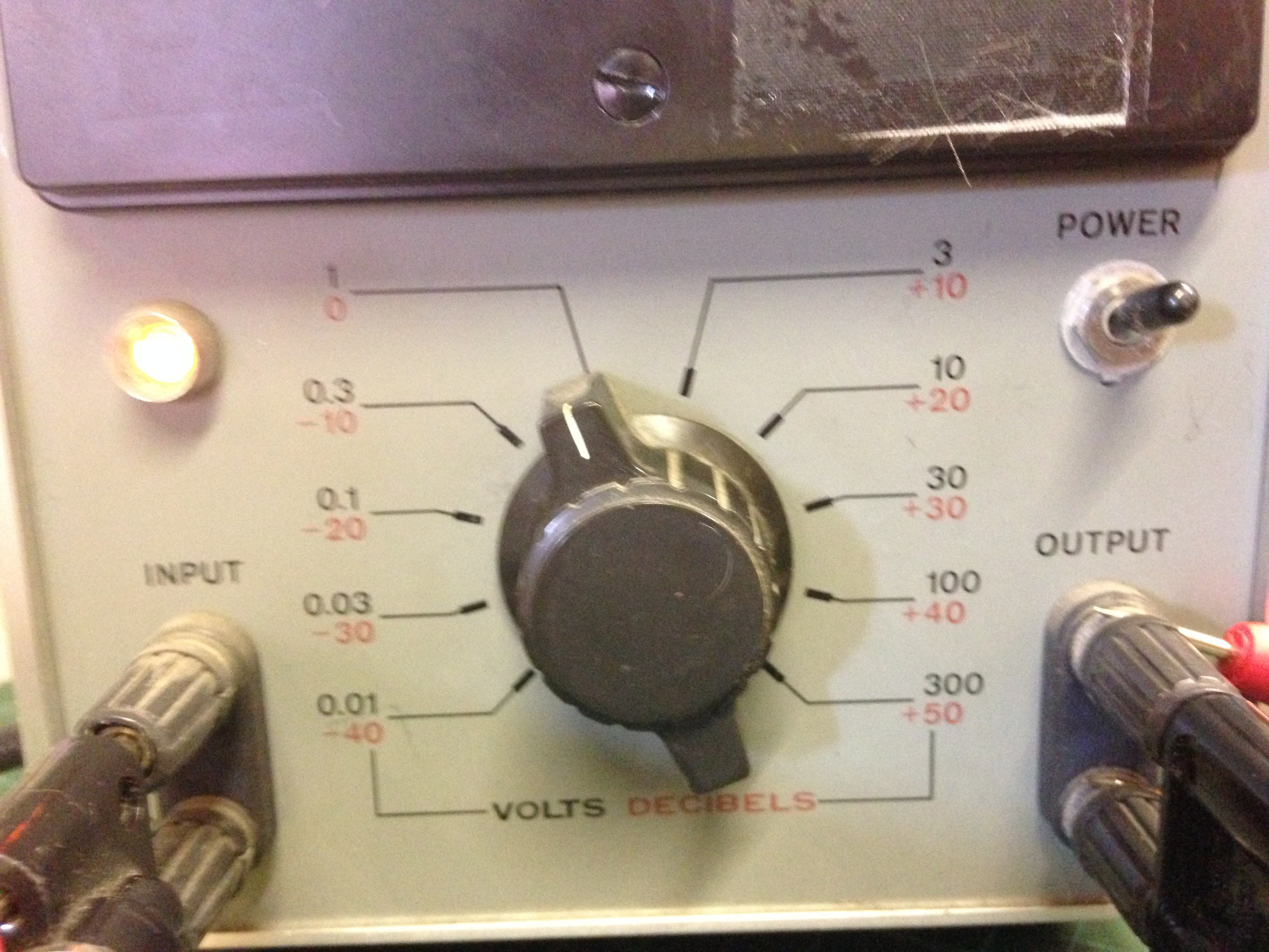
The main function of this meter is its a voltmeter whereby the range/scale is adjusted by the knob on the front:
So basically the input is just a voltmeter with a cleverly placed scale for dBm and dB.
The Output
The output terminal is the clever bit. The output is dependent on 2 factors:
- The load connected to it
- Its scale selected
With the input still set to 0.774V, I connected a 600R (using a resistance box) load to the output and measured its voltage. The reading was exactly the same as the input.
I then reduced the load to 300R and measured the voltage, this time it was 0.524Vrms
Remembering that:
This meant the the power dissipated in the load was 950uW or near as damn it 1mW. If you fed that the equantion to work out the dBm you'd get 0dBm.
So even though the load changed, the meters output changed accordingly to deliver the same power into a different load.
Another thing that I noted was that the output voltage range never changes with respect to the scale selected.
Before I get onto this, I first would first like to state how you read this meter:
Reading the meter:
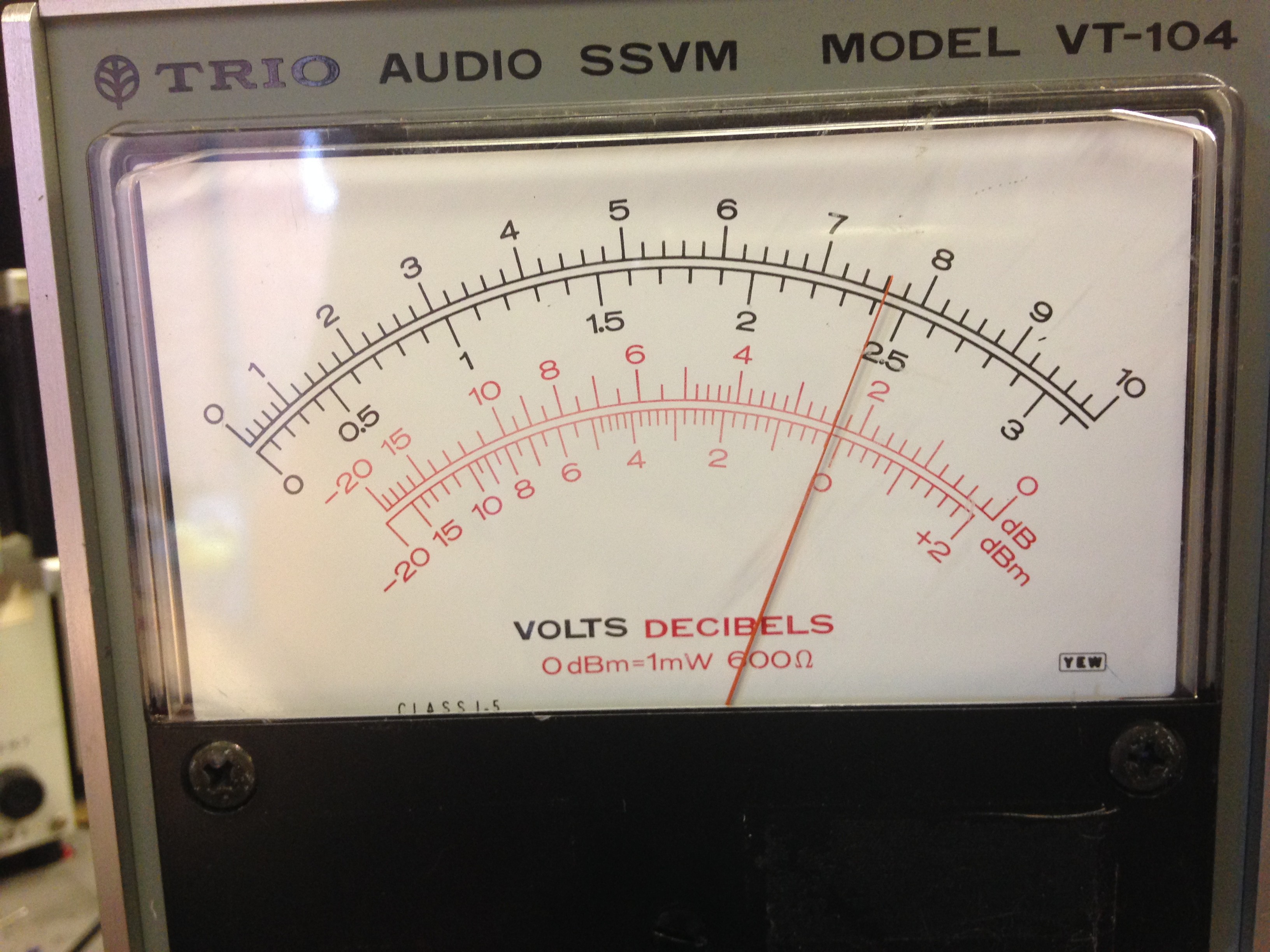
Above, the range is set to 0.3V fullscale and -10dBm. What this means is that on the dBm scale whatever the needle points to, you add the range selected.
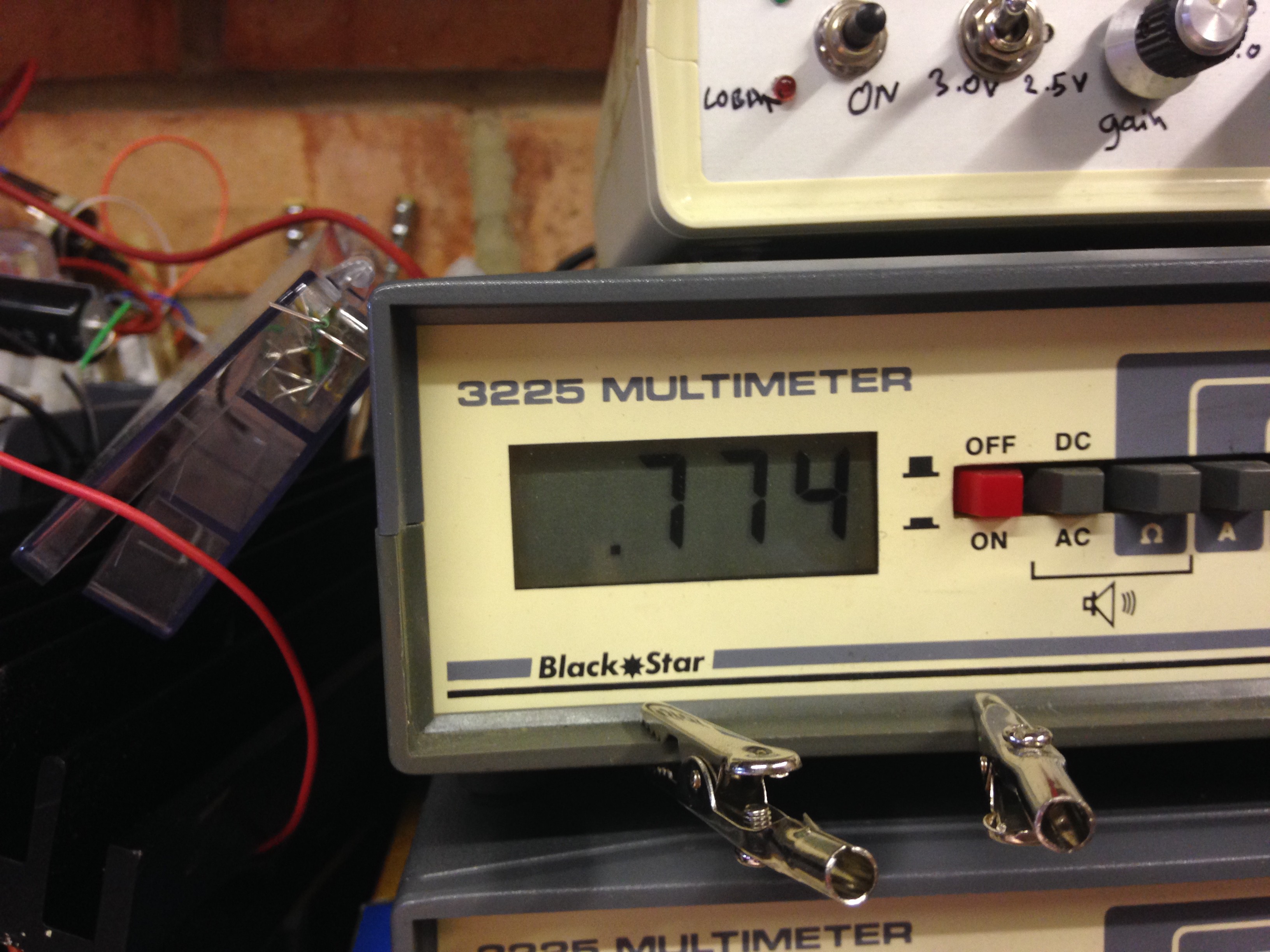
So above you see that the -10dBm range is selected and the needle is pointed to 0dBm, this means that the value is: 0 +(-10) = -10dBm, and this is furthermore proven by the voltage input which was 0.248Vrms as read off the digital bench DMM I had hooked up. Thus:
Q.E.D.
Back to looking at the output
So with information on how to read the scale, I left the input at 0.248Vrms and the selected scale to -10dBm. However the output into the 600R load was 0.783V.
I multiplied the output voltage by the full scale voltage (0.3) to get 0.2349Vrms. using this value I worked out that even though it was still delivering 0dBm into a 600R load, if fact it was scaling it against the -10dBm scale.
So when the output voltage = 0.774Vrms into 600R load on any selected scale, its at the 0dBm mark.
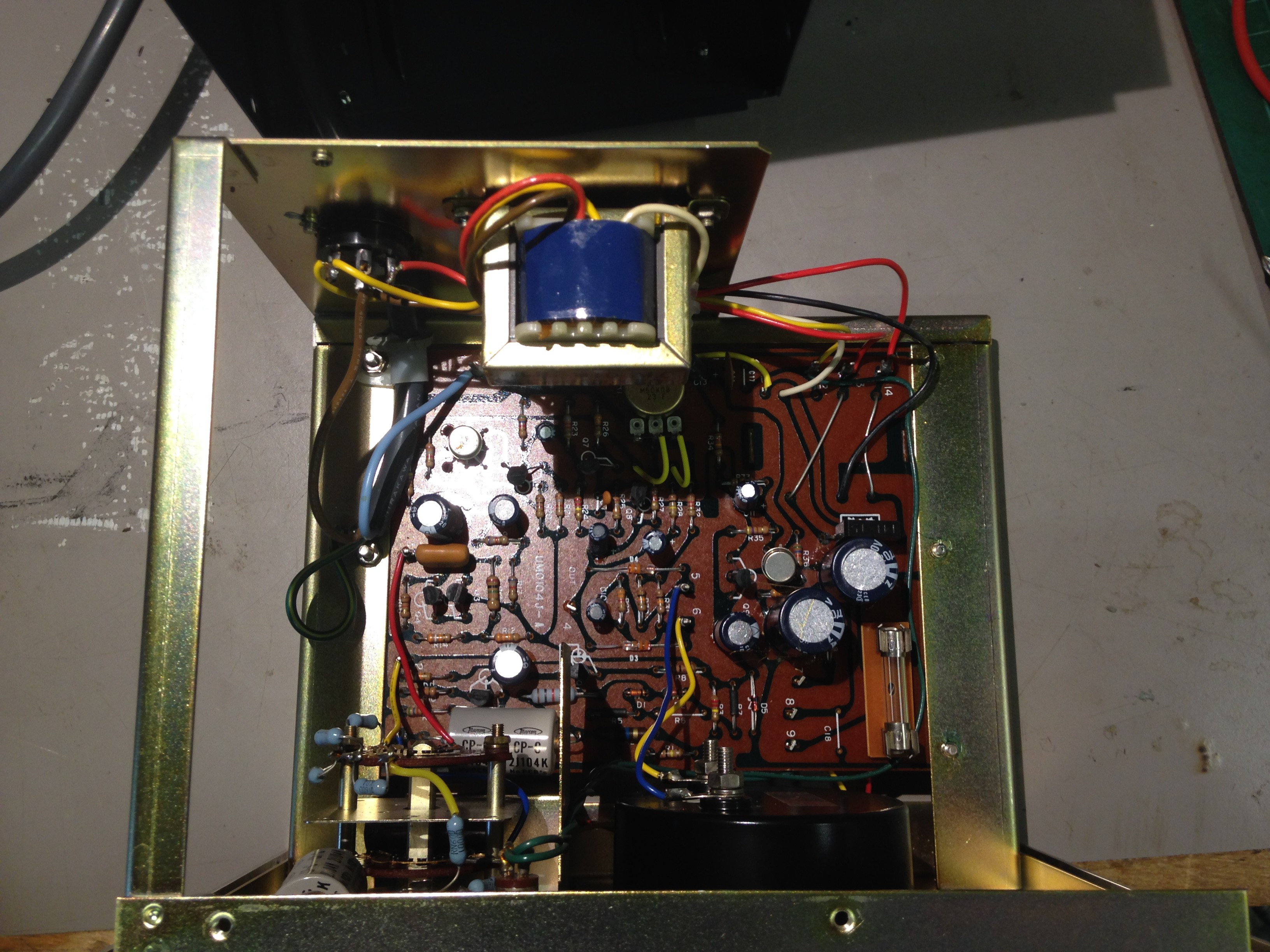
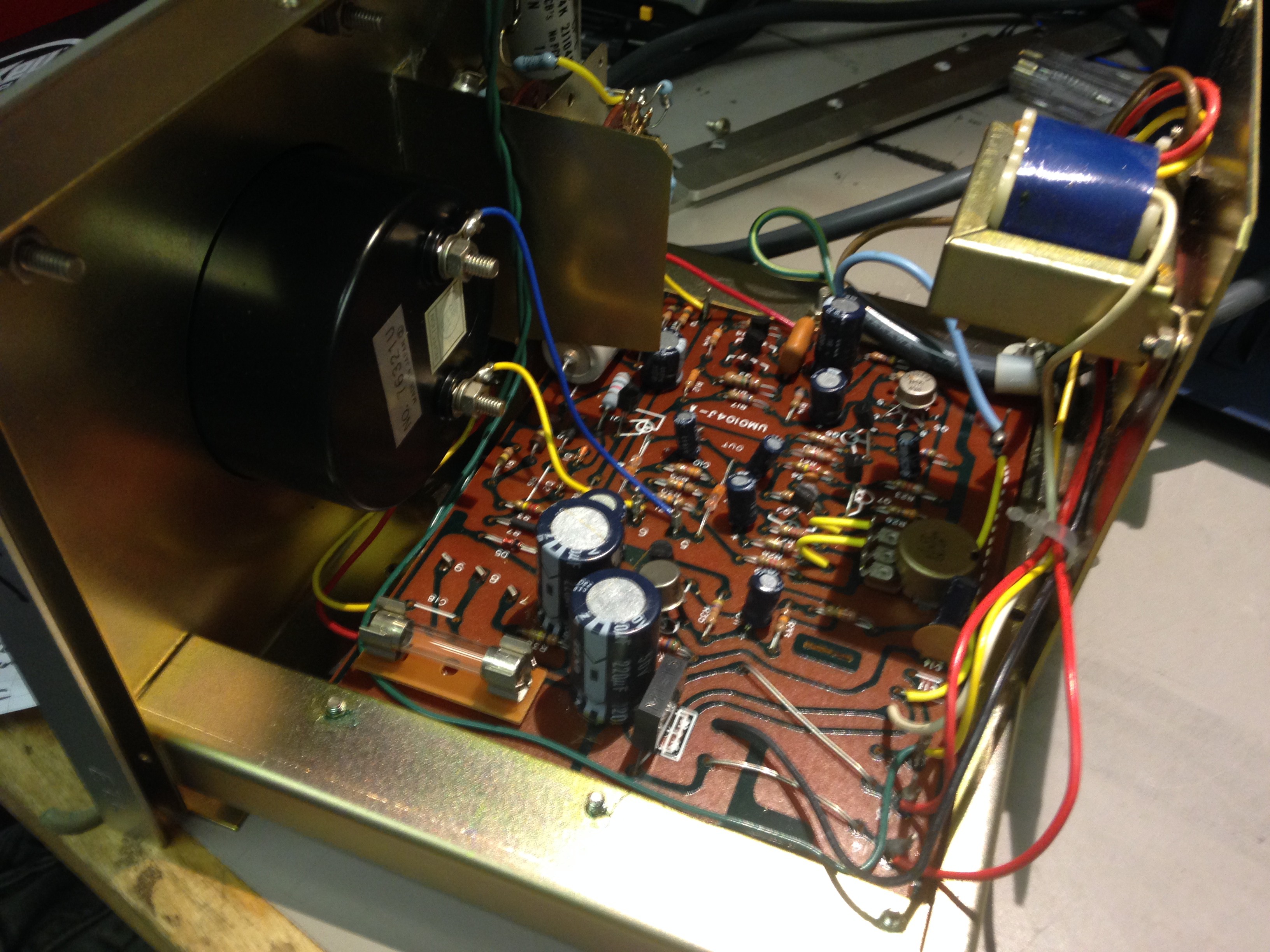
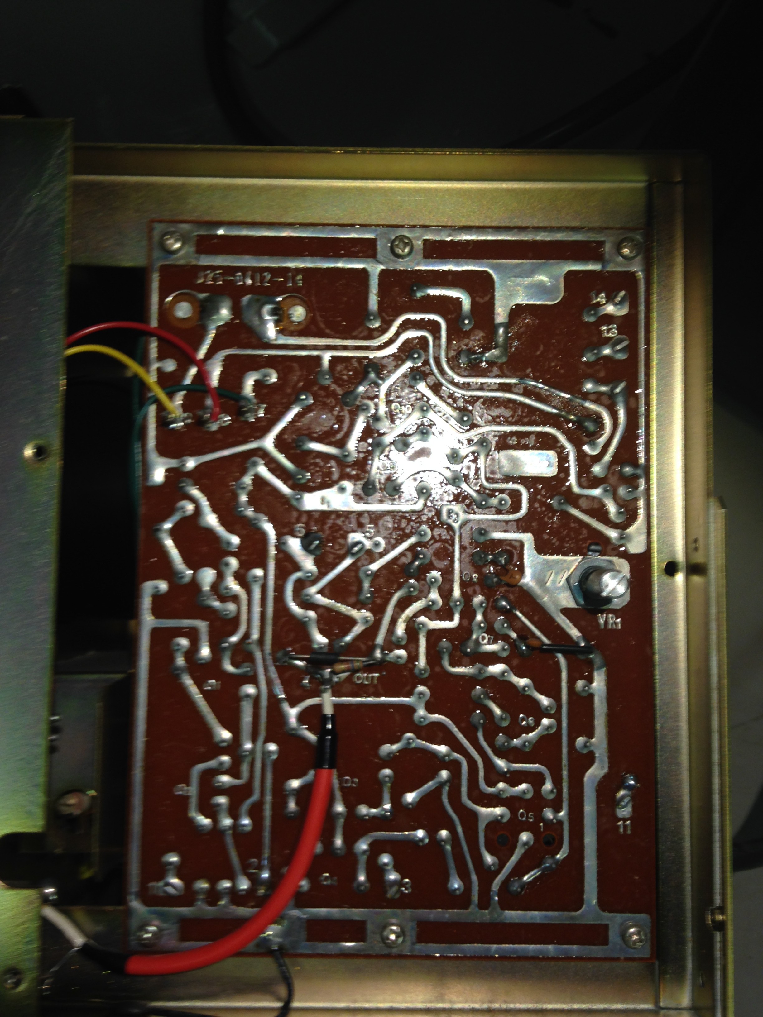
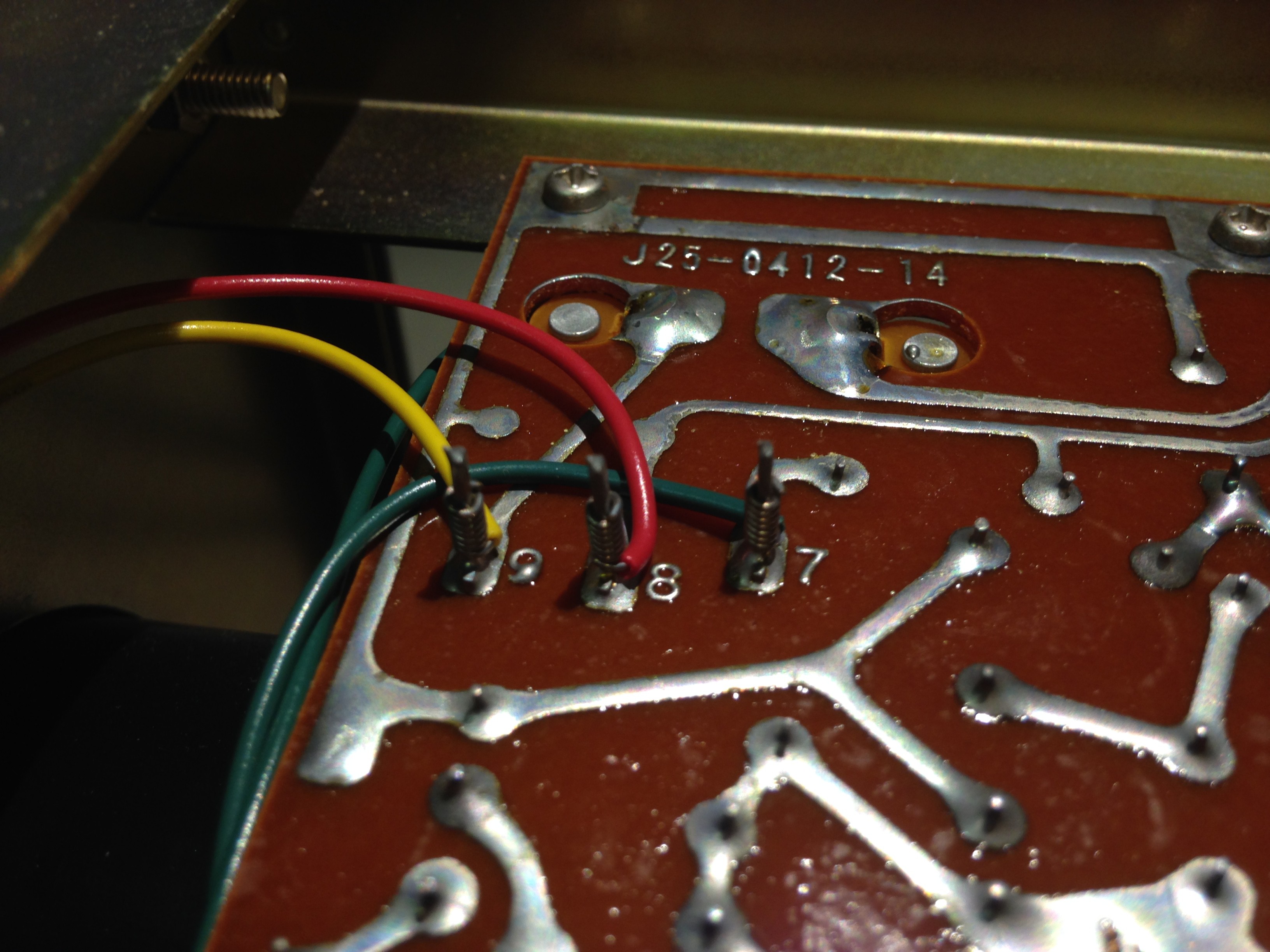
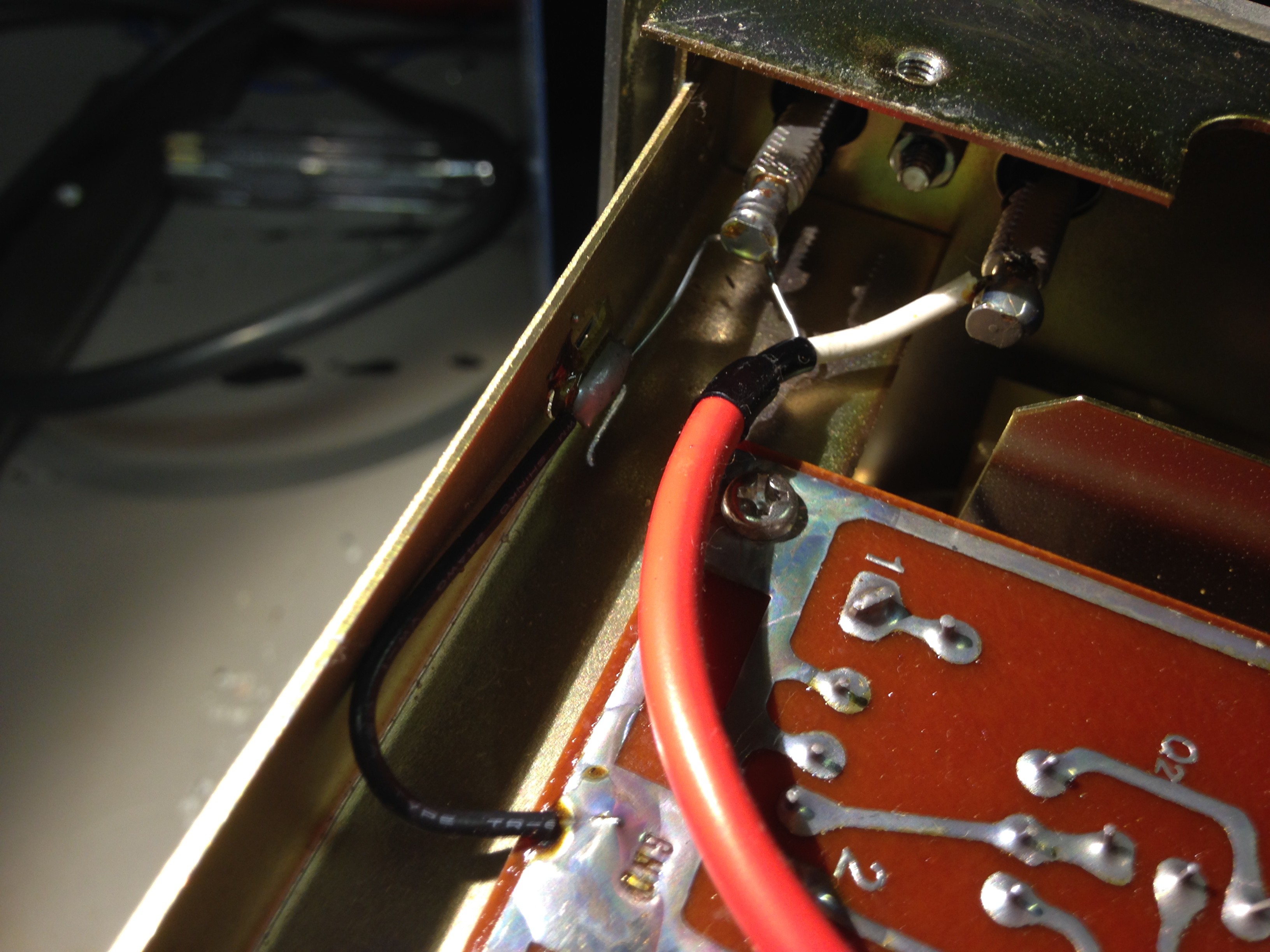
Shots of inside
Nice old school wire wrap!
AHHH! The Chassis is connected to the GND of the output! Beware!
 Tron9000
Discussions
Become a Hackaday.io Member
Create an account to leave a comment. Already have an account? Log In.