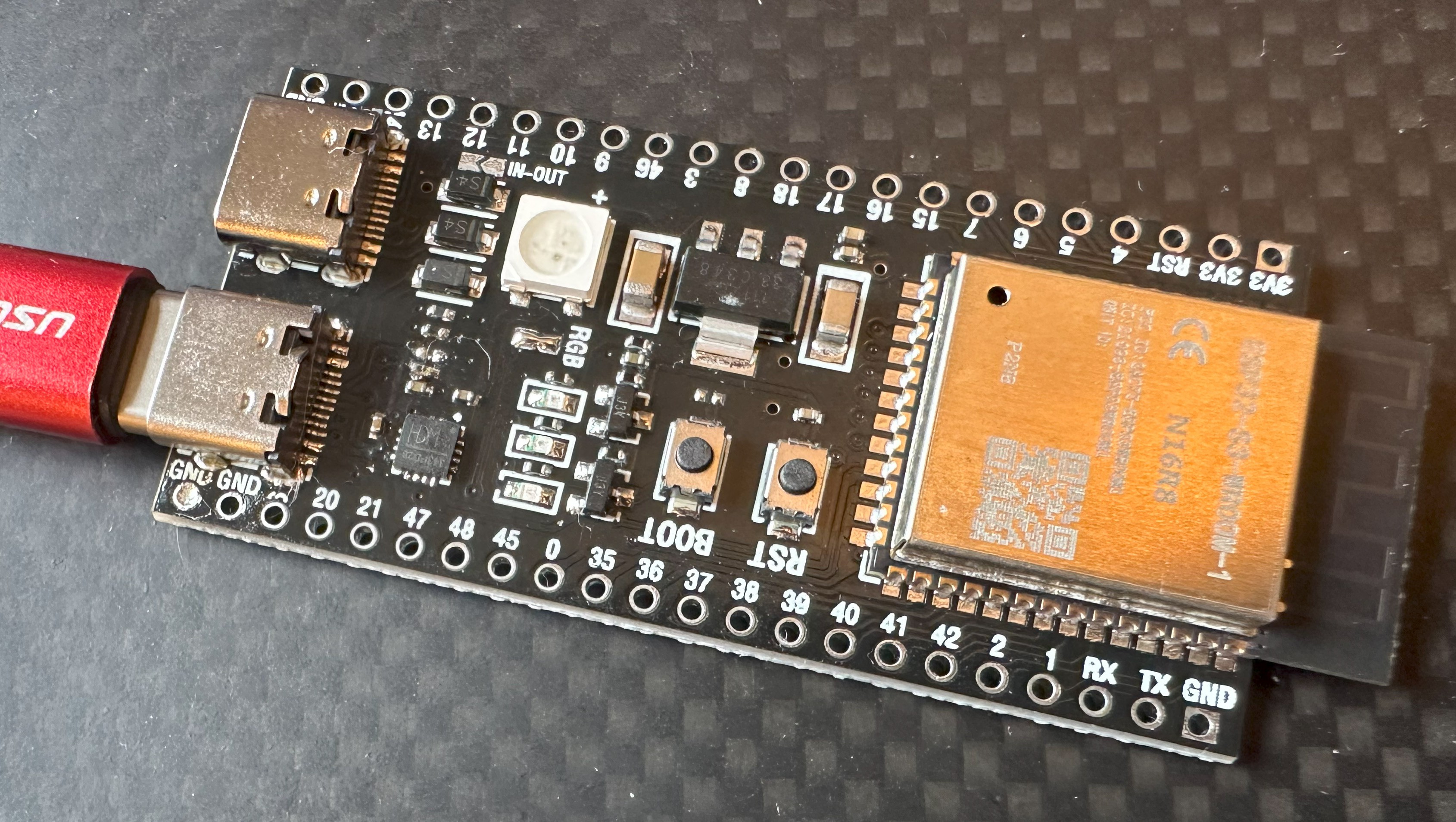
Can you tell the difference between these two pictures?


The astute among you will realize that the board works when the USB-C is plugged in one-way and not the other.
I bought this ESP32-S3 board as part of a batch and it just wasn't working like the others. Firstly, I discovered that the RGB link needs to be joined for the on-board WS2811 pixel to work. But more important was finding the cause of the fault.
My first, and incorrect assumption was to replace the USB-C socket. Which I did without anything coming to any harm, but it didn't fix the issue. What I'd failed to catch was the obvious: cable orientation behaviour is based on the CC1/CC2 lines. ALWAYS check those first.
Sure enough, my old friend the 5k1 was shorted, but only on CC1. So I removed it, but because I didn't have any 5k1 "in-stock", I then moved the 5k1 resistor from CC2 to CC1; which is why if you're really observant you'll see a missing resistor on the board. The CC1 orientation then powered the board without issue, and confirmed that the shorted 5k1 was the only problem.
So - after a few days I'll have the 0403 5k1 SMD resistor I need to make this board fully working again. My advice to board debugging? Never discount the most obvious things before leaping to the wrong conclusions - if I'd done that I'd have saved myself the dicey swapping of the USB-C socket with a hot air gun.
 The Virtual Traveller
Discussions
Become a Hackaday.io Member
Create an account to leave a comment. Already have an account? Log In.