 MOSFET
This paper investigates the failure of filter inductors in RF module power supply lines caused by ground short circuits resulting from improper installation. Proposed solutions include standardized installation practices and overcurrent protection circuit design. The application of negative feedback principles in protection circuits is thoroughly explained, along with how precise current limiting is achieved through parameter adjustment.
An RF module employing an active antenna—where the module powers the antenna via RF cable—experienced filter inductor burnout during operation. Analysis revealed that during feeder installation, the SMA housing may have contacted the RF port's inner core, causing a short circuit between the RF line and ground. This resulted in overcurrent and inductor failure.
Beyond standard installation practices, the circuit design must incorporate overcurrent protection to safeguard the main board from damage in similar scenarios.
The following overcurrent protection design is recommended for the circuit of a specific RF module:

The principle of overcurrent protection is analyzed as follows:
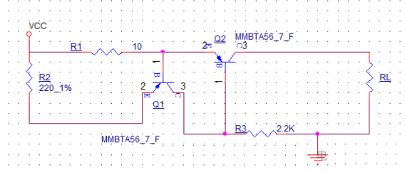
The circuit is simplified as above. When RL is under light load, the base of Q2 is pulled down to GND via R3 and remains in the conductive state. The current through R1 is small, resulting in a low voltage drop across the emitter and base of Q1. At this point, Q1 is in the cutoff state, and the circuit operates normally.
When RL's impedance decreases to a certain level (e.g., during a short circuit), the current through R1 increases. This causes the voltage drop across Q1's emitter and base to rise, turning Q1 on. Current flows through R3, raising the voltage at Q2's base. Q2 then tends toward cutoff, pulling the current down to achieve current limiting.
In essence, this circuit functions as a negative feedback circuit. By selecting appropriate transistor types and resistor values, the current limiting capacity can be adjusted. However, the precision of this circuit is relatively low, necessitating the inclusion of some margin.
Discussions
Become a Hackaday.io Member
Create an account to leave a comment. Already have an account? Log In.