 Frank Buss
You can program an iCE40 FPGA with a microcontroller, for example an Arduino with 3.3V IO. I tested it with a SparkFun SAMD21 Mini Breakout and a custom board. This is the setup:

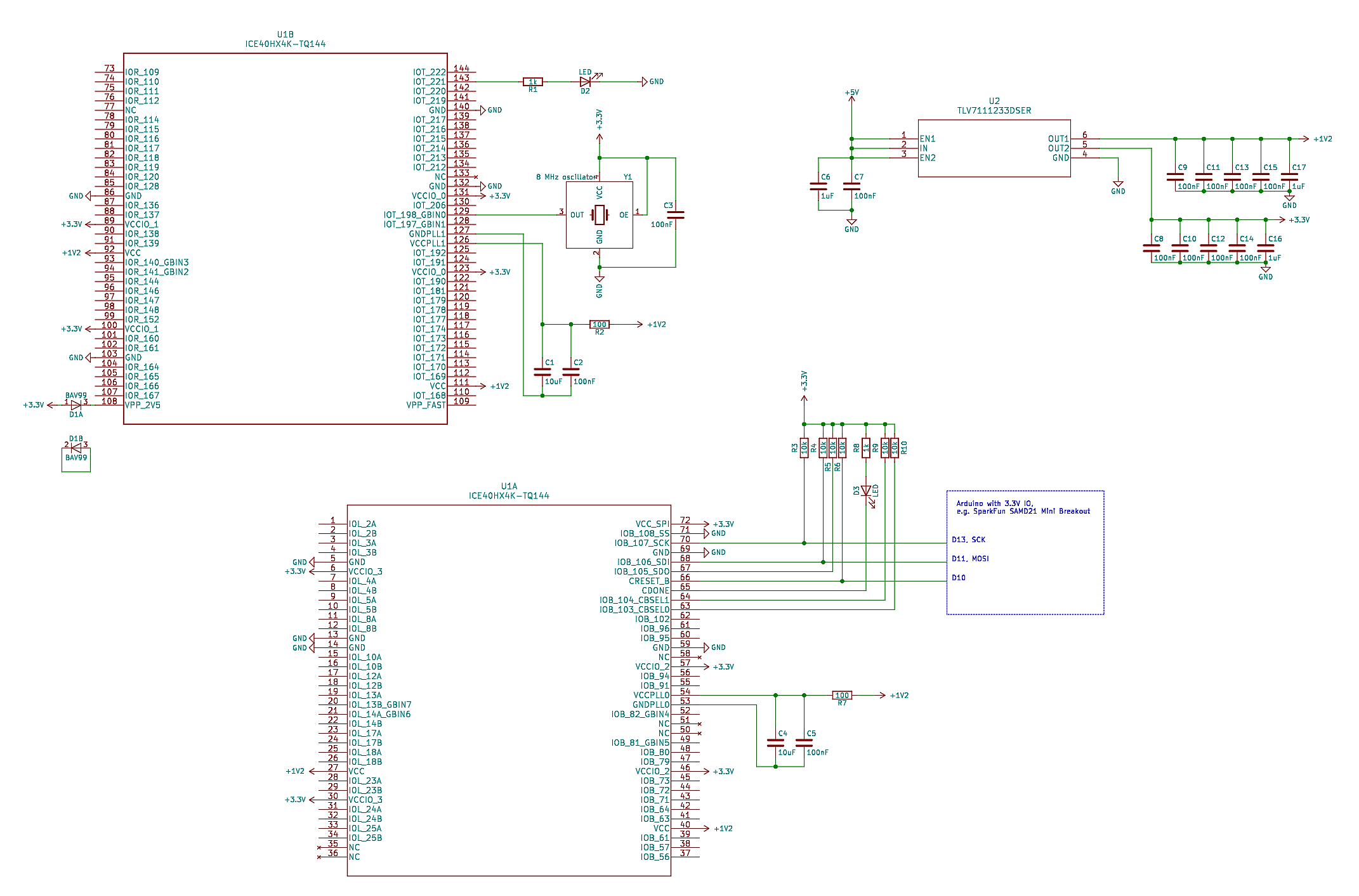
I have an additional flash and SRAM on my board, but you don't need this for a minimal test setup. This is the minimal circuit diagram how to use the FPGA (click on the image to zoom in) :
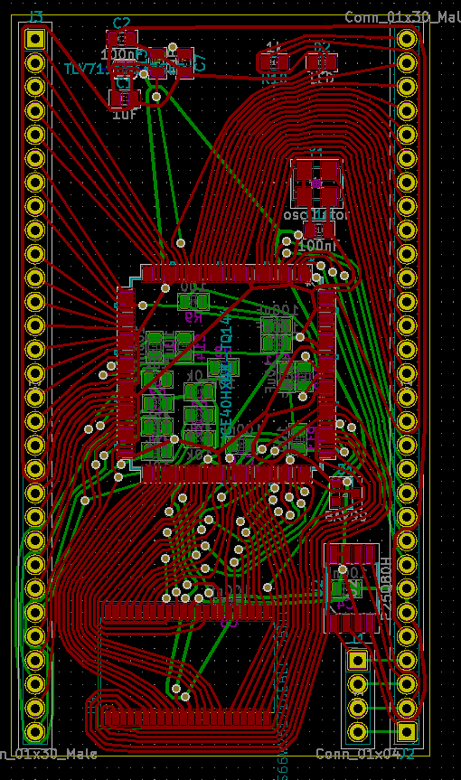
The routing was done with TopoR:
With the iCEcube2 IDE I wrote this test program:
library IEEE;
use IEEE.STD_LOGIC_1164.all;
use IEEE.numeric_std.all;

entity top is
    port (
        clk : in STD_LOGIC;
        led : out STD_LOGIC
    );
end top;

architecture Behavioral of top is
    signal blinker : natural range 0 to 25000000;
    signal blink : std_logic;

begin
    process (clk)
    begin
        if rising_edge(clk) then
            blinker <= blinker + 1;
            if blinker = 4000000 then
                blinker <= 0;
                blink <= not blink;
            end if;
            led <= blink;
        end if;
    end process;
end Behavioral;
When I compile it, I get the file "test_Implmnt/sbt/outputs/bitmap/top_bitmap.bin".
It is easy to configure the FPGA: First set the CRESET_B pin to low to reset the FPGA. Then hold down the SS pin and set CRESET_B to high, which starts the SPI slave configuration mode. You can then send the bin file data with the SDI and SCK pins.
On the Arduino side I wrote this script for the transfer:
#include <SPI.h>

#define RESET_PIN 10

#define ACK 6
#define NAK 21

const int BUF_SIZE = 128;

uint8_t buffer[BUF_SIZE];

void setup() {
  pinMode(RESET_PIN, OUTPUT);
  SerialUSB.begin(115200);

  SPI.begin();
  SPI.beginTransaction(SPISettings(1000000, MSBFIRST, SPI_MODE0));
}

void readBlock() {
  // wait for block start
  unsigned long t0 = millis();
  while (true) {
    if (SerialUSB.available()) {
      break;
    }
    unsigned long t1 = millis();
    if (t1 - t0 > 1000) {
      // timeout
      SerialUSB.write(NAK);
      return;
    }
  }

  // read data
  int received = SerialUSB.readBytes((char*) buffer, BUF_SIZE);
  if (received != BUF_SIZE) {
    // timeout
    SerialUSB.write(NAK);
    return;
  }

  // send with SPI
  SPI.transfer(buffer, BUF_SIZE);

  // acknowledge
  SerialUSB.write(ACK);
}

void loop() {
  // read command
  char cmd;
  while (true) {
    if (SerialUSB.available()) {
      cmd = SerialUSB.read();
      break;
    }
  }

  // execute command
  switch (cmd) {
    case 'r':
      // reset
      digitalWrite(RESET_PIN, LOW);
      delay(10);
      digitalWrite(RESET_PIN, HIGH);
      delay(10);
      SerialUSB.write(ACK);
      break;
    case 'b':
      readBlock();
      break;
    default:
      SerialUSB.write(NAK);
  }
}
And then I could upload the bin file with this Python script:
#!/usr/bin/python3

import serial

ACK = 6
NAK = 21

ser = serial.Serial('/dev/ttyACM0', 115200, timeout=1)

# read and evaluate response
def readResponse():
    d = ser.read(1)
    if len(d) == 0:
        raise Exception('response timeout')
    if d[0] == ACK:
        return
    if d[0] == NAK:
        raise Exception('NAK received')
    raise Exception('unkown response')

# send a command
def sendCommand(cmd):
    ser.write(cmd.encode())
    readResponse()

# send a block
def sendBlock(data):
    ser.write('b'.encode())
    for d in data:
        ser.write([d])
    readResponse()

# read file and add some bytes at the end for the required 49 clocks for configuration
inputFile = open('top_bitmap.bin', 'rb')
bufSize = 128
data = bytearray(inputFile.read()) + bytearray([0] * (bufSize * 2))

# reset FPGA
sendCommand('r')

# send data to FPGA
while len(data) > bufSize:
    block = data[:bufSize]
    data = data[bufSize:]
    sendBlock(block)
At the end of the upload the CDONE pin goes low, if there was no error. I added an LED to it which goes off when it is done.
The other LED on pin 143 blinked with 1 Hz after the configuration, as programmed in the VHDL file.
Discussions
Become a Hackaday.io Member
Create an account to leave a comment. Already have an account? Log In.