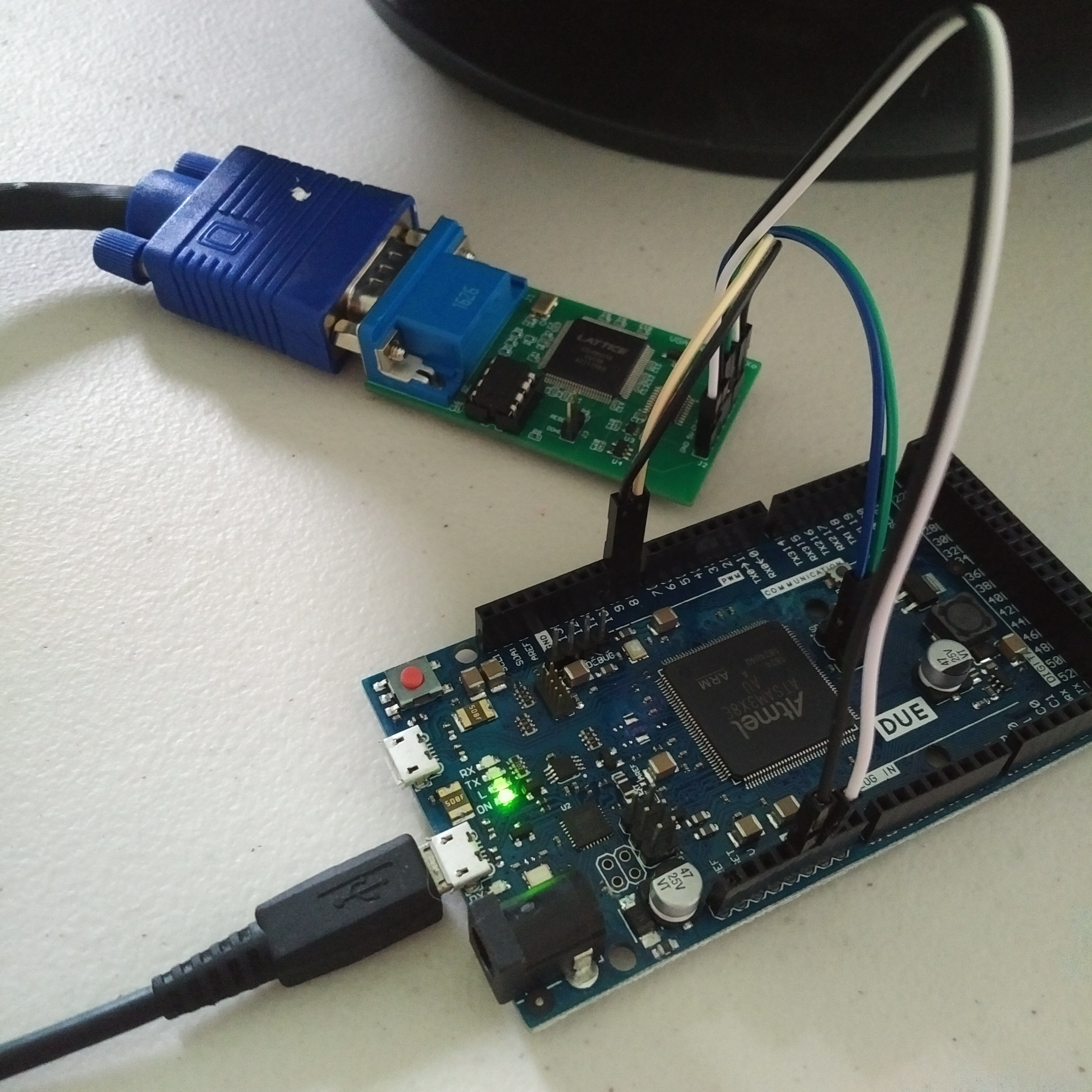
 Dan O'Shea
When I first dipped my toe into the world of FPGAs and designed the VGA1306 (also known as 'easy_VGA') board, it was with the set goal of emulating the ubiquitous 128x64 pixel SSD1306 monochrome OLED screen – using a Lattice iCE40 FPGA to read in the SPI signals meant for the little screen, and then output up-scaled black and white VGA signals to a big screen instead. And so with this goal in mind, using a 25MHz oscillator for 640x480 pixels @ 60FPS and only a single resistor on each of the red / green / blue lines was more than enough – the fact that the RGB signals could then also be set in different combinations to achieve all eight glorious colours of the 3-bit RGB rainbow was a pure bonus!
But as I learned more over time and developed a taste for FPGAs, I have been able to squeeze more and more potential out of this minimal PCB – using it as a VGA output for the Nintendo GameBoy, as an old-school Snake or Breakout game, and even as an 80x60 character 'text-mode' video card for Arduino BASIC or a VT100 terminal emulator.
Inspired by Ben Eater's recent “world's worst video card” project where he used a 10MHz oscillator to output four-pixels-at-a-time within a standard 40MHz pixel clock timing, I started thinking about ways to work within the limitations of my fixed 25MHz oscillator (with no PLL available on the FPGA), and the hard-wired 3-bit RGB palette, and how I might be able the push it a little further... it occurred to me that I could possibly double my 8 colours, up to 16 colours, if I set it up so that some pixels only appeared every second frame – so they would then appear as a darker shade of that colour? At first this just resulted in a lot of flickering, and I quickly realised that the frame rate would need to be much higher in order for a pixel that was only appearing every other frame to be perceived as a steady pixel of a darker shade, rather than as a quickly flickering pixel of the same shade!
I found details for
standard VGA timings running at up to 100FPS, and figured out that if
I could divide my 25MHz clock by one-and-a-half, then I would be
close to the right frequency for pushing out those
four-pixels-at-a-time. I managed to find some handy divide-by-1.5
verilog code in an old comp.lang.verilog newsgroup post from 2005,
but at this point another problem popped up – none of the MANY
flat-screen monitors in the house were actually capable of running at
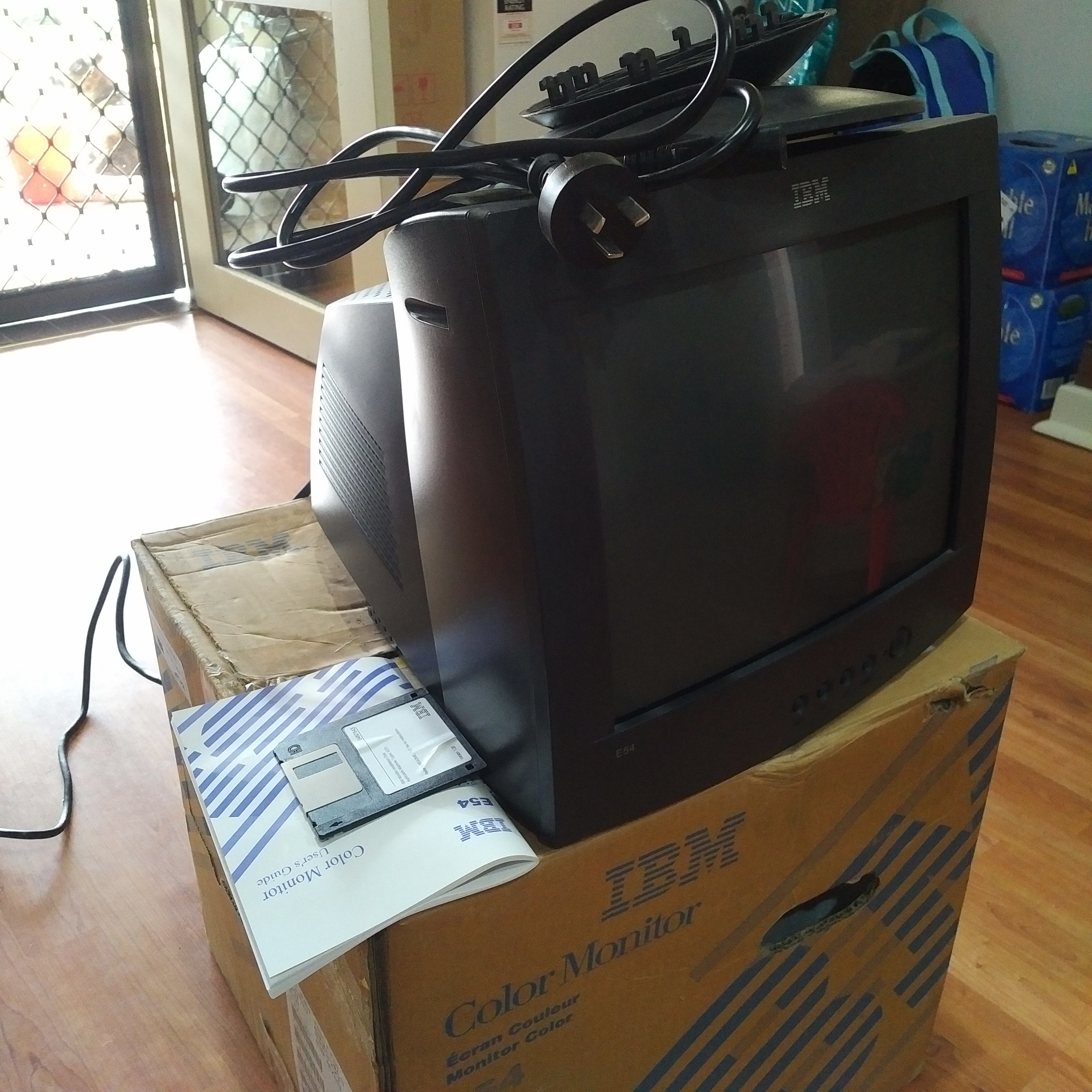
100Hz! But, I remembered an old IBM CRT monitor that had been sitting
in a corner gathering dust at work, and I brought it home with me the
next day – still in the box, including user manual and 3½ inch
floppy disk.
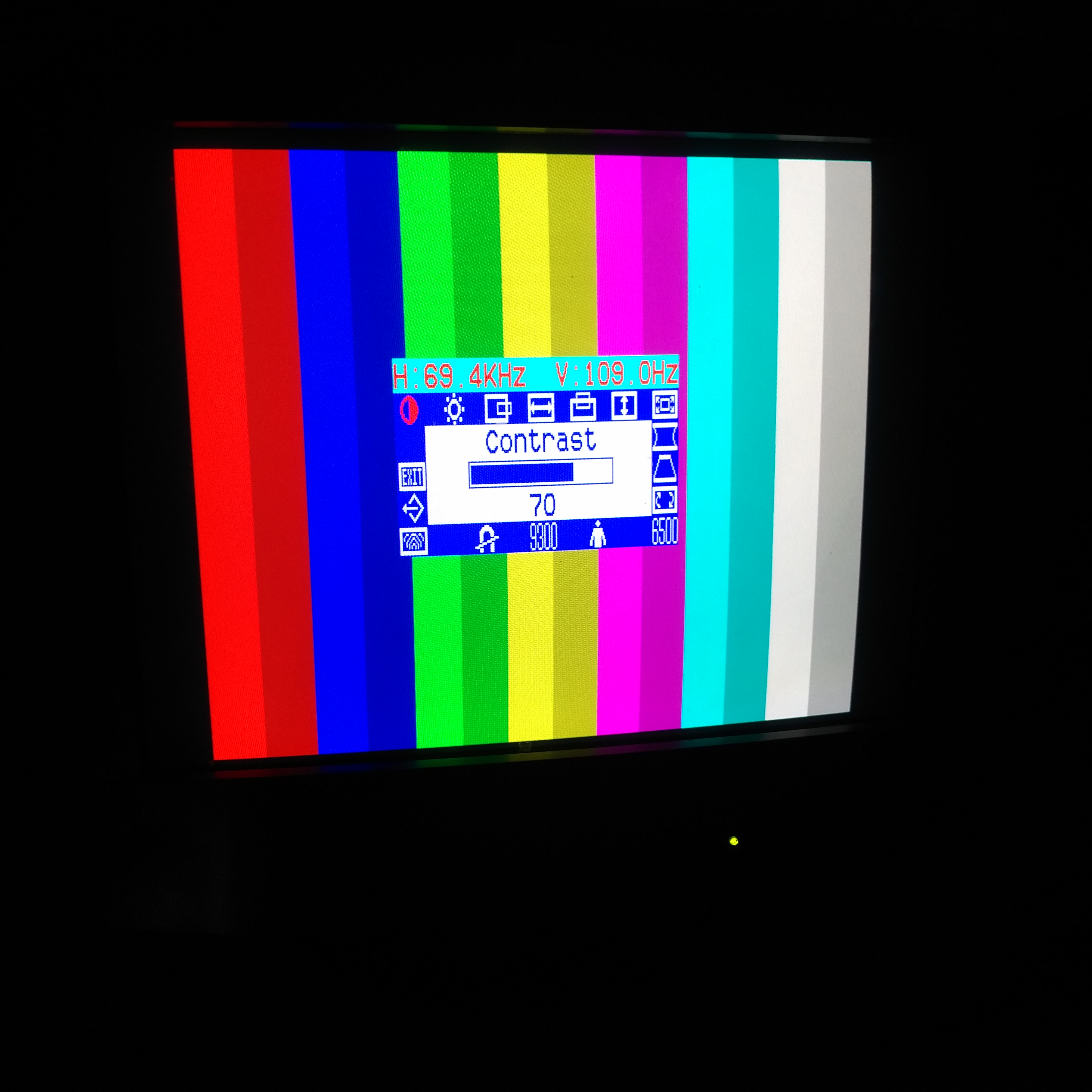
Happily, this
monitor has a scanning frequency of up to 120Hz vertical and 69kHz
horizontal – now that's more like it! After some experimenting I
was able to push it up to 109Hz / 69.4kHz, and the flickering went
away, and my 15 colours were on
screen 😃 (not 16 colours – no darker shade of black, sadly).
Recording video of CRT monitors is difficult at the best of times, but the frequency I am running it at here makes it even more troublesome – I was eventually able to get some good recordings though using an iPhone app that allows for manual adjustment of the shutter speed (also, by setting the shutter speed to 1/110 you can actually see the bars for the darker colours switching off and on).
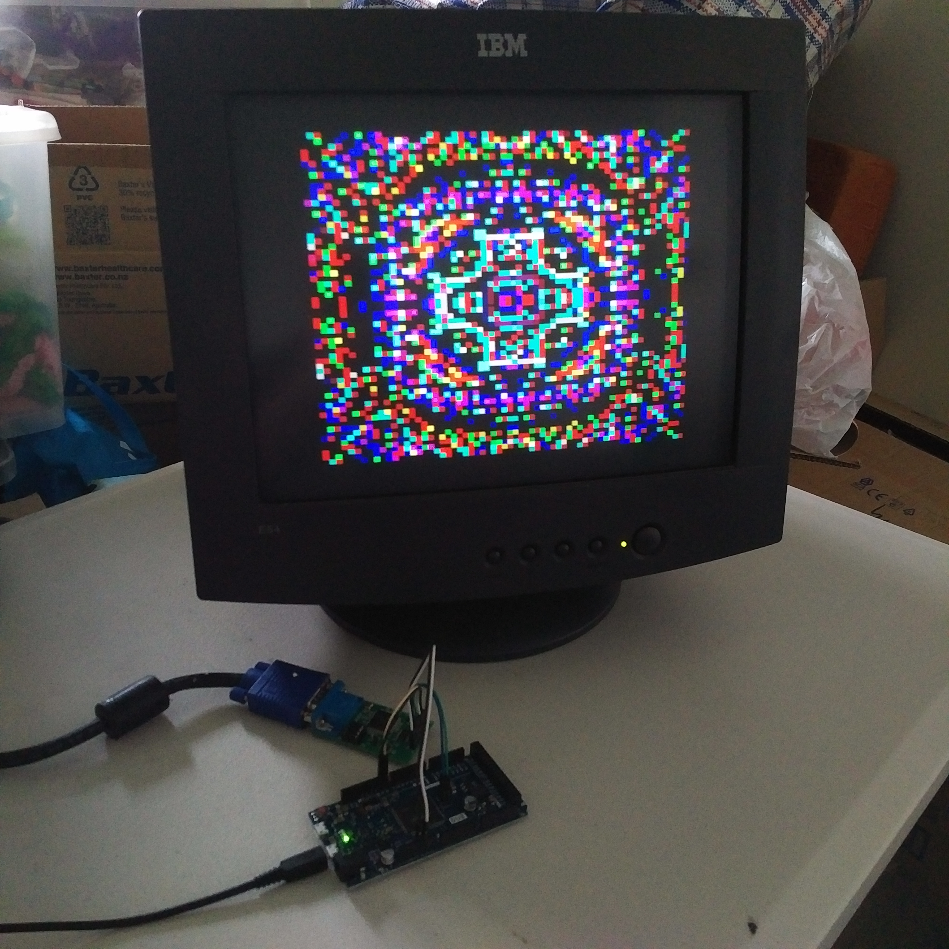
Wondering what a
good application of this new capability may be, I found David
Hansel's Altair 8800 simulator for the Arduino Due – specifically
the extension for simulating the original Cromemco Dazzler graphics
card! The Dazzler gave an Altair 8800 the ability to output RGBI (15
colour) video at 64x64 pixels and was 'cutting-edge' at the time.
After some time studying David's code to understand what it was
doing, and then some time spent adapting it and writing / troubleshooting some of my own code, here is the VGA1306 board emulating a Cromemco Dazzler running Li-Chen Wang's original Kaleidoscope demo:
Discussions
Become a Hackaday.io Member
Create an account to leave a comment. Already have an account? Log In.