 K.C. Lee
I made a digital clock. Originally I planned to use a VFD, but the user interface on a 4 digits was too much of a limitation. (I already have to cramped the UI on my STM8 timer with 16x2 LCD)
I used a STM8S003, 74HC595 and a couple of the cheap green 7 segment displays. The display efficiency is actually not bad as the entire clock runs on 5V at ~20mA.
The RTC is implemented in firmware using a DDS for fine frequency adjustment. A supercap allows the STM8 to work for a few minutes during a power failure. The LED driver is on a separate rail.
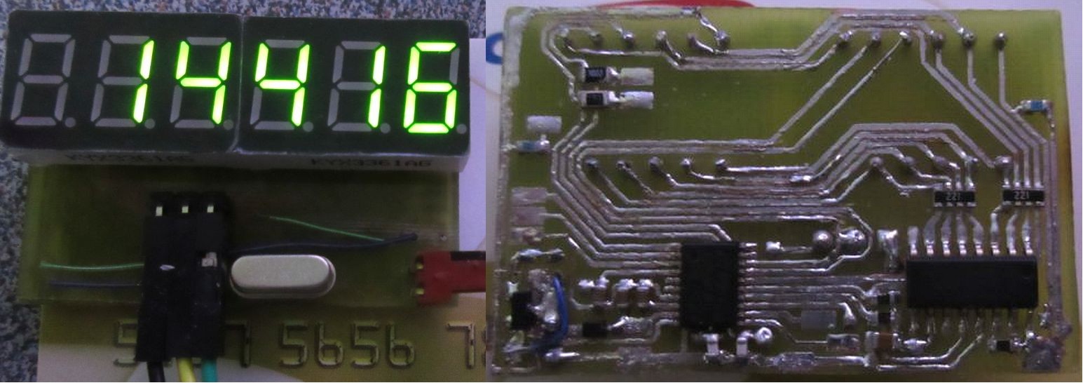
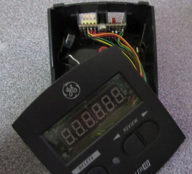
The PCB is wired to the original (stripped) PCB to use existing buttons. The same GPIO for the common cathode driver when off-duty is used for polling the buttons.
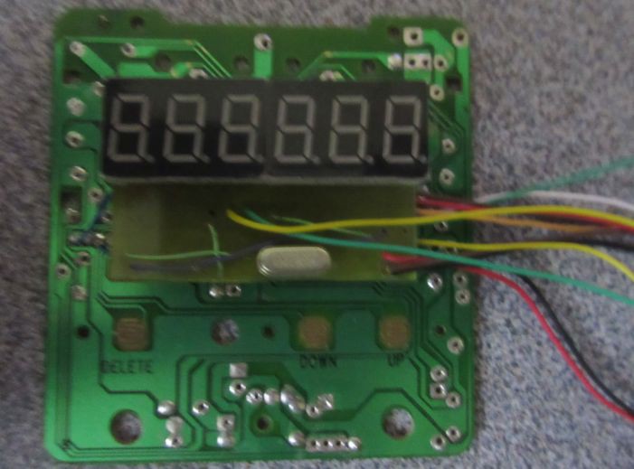
I could have used the STM8 alone, but the 74HC595 frees up a few GPIO lines. UART, I2C, a Timer pin, power and the debug interface are connected to the headers on an I/O panel PCB using the existing RJ11 cutouts.
(I have since changed the power connector to a MicroUSB as it has much better latching.)
Still working on the user interface and other features.
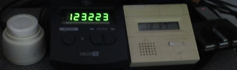
Side by side view of the old traveler's Casio clock it is replacing as it is much harder to read during night time.
My blog: https://hw-by-design.blogspot.com/2019/11/stm8-led-clock-part-1.html
Github: https://github.com/FPGA-Computer/LED-Clock
Initial release: bare minimal feature.
It is one of those things that once it works, you don't want to mess around too much.
Discussions
Become a Hackaday.io Member
Create an account to leave a comment. Already have an account? Log In.
BTW, I like the green display, anything other than red makes a nice change. I was drooling over some non-red displays (green, amber, blue, white) but that's just my eyes getting bigger than the displays.
Are you sure? yes | no
It is intended as a clock under my monitor, so there are few colours I would pick. Red LED is screaming for attention, blue has the cheap cheesy Chinese electronic look. I would use white, but it isn't good for night time - not that I turn on the light time theme (yet). I have some amber blacklit 16x2 LCD from a surplus that was just too wide for this. :(
i would love the newer darker green but can't find it. Those are insanely efficient - got one light up from tiny leakage current flowing between my finger and soldering iron.
Are you sure? yes | no
Re-using the mechanical parts of otherwise uninteresting gadgets or appliances is a good idea. I also like the 80s design (even if it's more likely a naughties gadget).
Are you sure? yes | no
Hahaha, great minds think alike. I have a bedside alarm clock radio which used to have a flip display, long since dead. I ripped that out and put a newer, but still ancient NS5316 clock chip and LED display. Chip drives the segments directly. Doesn't matter that only a mA or two is sourced, bedside clocks are not supposed to be bright, which is why VFDs could not displace LEDs completely in this niche. A transistor driven from the alarm output turns on the radio.
Are you sure? yes | no
VFD also have limited life (vs how long I tend to keep my stuff.) My Casio clock is from 1982 and I don't tend to throw away stuff until they are totally useless even for repurposing. :P
Are you sure? yes | no
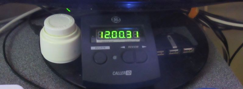
It was a 90's CallerD ($10). I damaged the flex glued on conductive ink PCB to the LCD.
It has the look of the 80's Casio clock that I am replacing. A couple of testers (LC, transistor tester) I made with integral AA battery holder which acts as a stand are following the same idea. (added picture above. Casio clock is white)
Are you sure? yes | no