 Christoph Tack
General
Understanding Antenna Specifications and Operation : Application Note AN-00501
- The quarter wavelength on 433MHz is 17cm.
- VSWR < 2.0 is acceptable. Less than 10% of the power will be reflected back to the transmitter.
- Baluns avoid RF-radiation and noise pickup from the feed line:
- These baluns should be placed as close as possible to a balanced type antenna (feed point).
- Not needed for monopole antennas because they're unbalanced.
- FCC CFR Part 15 forbids standard connectors like SMA. RP-SMA is allowed.
- The frequency of lowest VSWR is not necessarily equal to a resonant frequency of the antenna.
- lowest VSWR = antenna impedance closest to 1 on Smith chart.
- resonance = antenna impedance is purely resistive, on X-axis on Smith chart.
Antenna testing
| VSWR measurements on quarter wave monopole antennas don't mean much in reality. So the measurements below should be taken with a grain of salt. The λ/4 monopole antenna performance strongly depends on the size and orientation of the ground plane and hand capacity etc... An antenna with a good VSWR in a lab setup (using a large perpendicular ground plane) doesn't guarantee it will perform well in real life conditions, when it's connected to your HT. |
- It would be better to attach ferrite beads on the coax cable near the antenna. In case of unbalances, this will limit CM-current (less effect when coming closer with your hand, etc...)
- Real world antenna testing
- Testing Ham Radio HT Antennas (Signal Stick, Nagoya, Diamond)
- #188 Antenna Tutorial incl. cheap DIY Antenna Tester (LoRa, ESP32)
- Radio link budget calculator
- better to use a tool that calculates MPPL (multipath power loss, see theThingsNetwork) instead of free space losses
- 434MHz TX, 0dBi antenna, 0dB cable loss: 20dBm → 100m→ RX: -45dBm
- Doubling distance will lower received power with 6dB
Antenna tuning
- Monopole antennas must be used with a ground plane
- Use smith chart to find resonant frequency. That will be where the graph crosses the horizontal axis.
- Tune the length of the elements to get the impedance at the resonant frequency closer to 50ohm.
- If antenna tuning is not possible (because of a COTS-antenna), you can use a matching network to match your radio's impedance to the antenna impedance in an effort to get the VSWR < 2.0.
λ/4 Monopole antenna characteristics
- Zin = 36Ω at the resonance frequency (over an infinite ground plane)
- Maximum gain = 5.15dBi (3dB more than dipole antenna)
- The go-to antenna here is a ground plane antenne. The resonant frequency can easily be tuned by cutting the monopole, while the impedance can be tuned by folding the radials.
- Monopole antennas need a ground plane, so you shouldn't use them with a u.fl to SMA cable assembly. Dipole antennas can be used with u.fl-SMA cables.
- Monopole antennas can be used with edge soldered SMA-connectors.
- All 433MHz whip antennas on the market seem to be monopoles. I guess dipoles would make them too long.
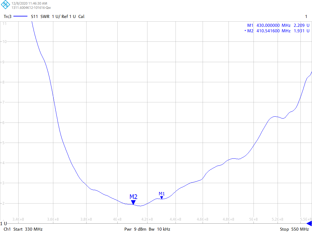
AliExpress WirelessLink store PM433-ZB165BM (71A, 433MHz 16.5cm ZT SMA)
The characteristics have been measured with a direct connection to the VNA. No ground plane added. This will impact bandwidth as well as center frequency.
The default antenna frequency is by no means 433MHz, as can be seen in the first graph.
Monopole antennas should always be measured with a reasonable size ground plane (radius > lambda/4).
Measurement on Smith chart with serving tray as gnd plane:
- Resonance: Z = 27 + 0j ohm at 408.3MHz
- Minimal VSWR: Z = 28.5 - 3.8j ohm at 404.9MHz
Measurement when SMA taped with Cu-tape to the edge of Al-GND plane (800x2000mm)
- Resonance: Z = 78 + 0j ohm at 417MHz
- Minimal VSWR: Z = 74.5 - 5.6j ohm at 414MHz
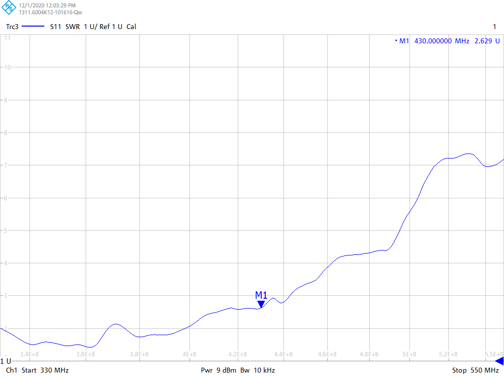
AliExpress WirelessLink store PM433-ZB165BM (71A, 433MHz 16.5cm ZT SMA) : manually shortened
Inexperienced as I am,I cut away a few centimeters to improve the impedance match in the 430MHz region. The open end has been protected by double folding heat shrink tube over the end and then adding extra heat shrink tube over it.
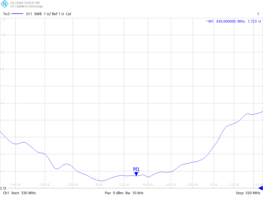
Of course, when measured with a ground plane, things look differently:
- Resonance: Z = 22 + 0j ohm at 453.1MHz
- Minimal VSWR: Z = 30.4 + 7.3j ohm at 464MHz
Measurement when SMA taped with Cu-tape to the edge of Al-GND plane (800x2000mm)
- Resonance: Z = 109 + 0j ohm at 477MHz
- Minimal VSWR: Z = 67 - 20.8j ohm at 435MHz
What I really should have done is leave the antenna as is and use an antenna tuning circuit to resonate the antenna at 434MHz. A guide explaining this process well can be found here.
Super-Elastic Signal Stick
I didn't want to destroy this one. It's made of Nitinol. As it's also a monopole, I measured it on the serving tray. The serving tray has a hole in the center for a female SMA/female SMA adapter. As this antenna has an SMA female connector, an extra SMA male/SMA male adapter was needed. The SMA-cable is a 1m of RG-142.
Testing Ham Radio HT Antennas (Signal Stick, Nagoya, Diamond)
Measurement on Smith chart with serving tray as gnd plane:
- Resonance: Z = 61.1 + 0j ohm at 446MHz
- Minimal VSWR: Z = 49.3 - 4.6j ohm at 442MHz
Measurement when SMA taped with Cu-tape to the edge of Al-GND plane (800x2000mm)
- Resonance: Z = 95 + 0j ohm at 461MHz
- Minimal VSWR: Z = 84 - 21j ohm at 454MHz
Yaesu FT-65E original antenna
Measurement on Smith chart with serving tray as gnd plane:
- Resonance: Z = 17.4 + 0j ohm at 380.3MHz
- Minimal VSWR: Z = 39.8 + 20.9j ohm at 400MHz
Measurement when SMA taped with Cu-tape to the edge of Al-GND plane (800x2000mm)
- Resonance: Z = 51 + 0j ohm at 417MHz
- Minimal VSWR: very close on 417MHz
Normal mode helical antenna
TTGO LoRa 32 433MHz antenna
I had been warned that this rubber ducky antenna with 40mm long plastic cover is not suited for tracking weather balloons. When connected to the edge of a (800x2000mm) ground plane the antenna seemed to resonate at 466.8MHz, with the plastic cover removed the resonant frequency even went up to 504.4MHz.
Using this manual, we can replace the coil by a new one tuned to 404MHz, which will be more suited for tracking weather balloons.
I used 0.8mm enameled Cu-wire instead. Starting with 30 windings and cutting them of one by one to tune them. Remember to place back the plastic cap before measuring with the VNA, because the cap lowers the resonant frequency of the antenna about 20 to 25MHz.
Sleeve dipole antenna, aka bazooka
A balun near the antenna is definitely needed to reduce the effect of the environment on the antenna. It will also make it easier to tune the antenna.
- Sleeve Dipole Antenna Design and Build : uses ferrite beads near the antenna to reduce CM-current.
- Extended PMR Antenna UHF/PMR446 : uses a Coiled-Coax Choke Balun near the antenna.
- Make Your Own FM Vertical Sleeve Coax Antenna : no balun at all
Flower pot antenna
- Half-wave flower pot (HT2T antenna from CB-world)
- Flower pot for 2m & 70cm
Discone antenna
Wideband, suitable for scanning
Folded dipole
todo
Discussions
Become a Hackaday.io Member
Create an account to leave a comment. Already have an account? Log In.