-
CC3200 SimpleLink Development Page.
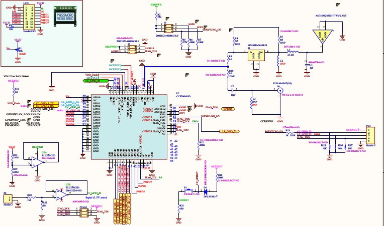
03/14/2016 at 15:08 • 0 commentsStep 1 is to add LCD and some analog interface to my CC3200MOD board. Schematics link.
CC3200 SimpleLink Wi-Fi and Internet-of-Things solution, a Single-Chip Wireless MCU.
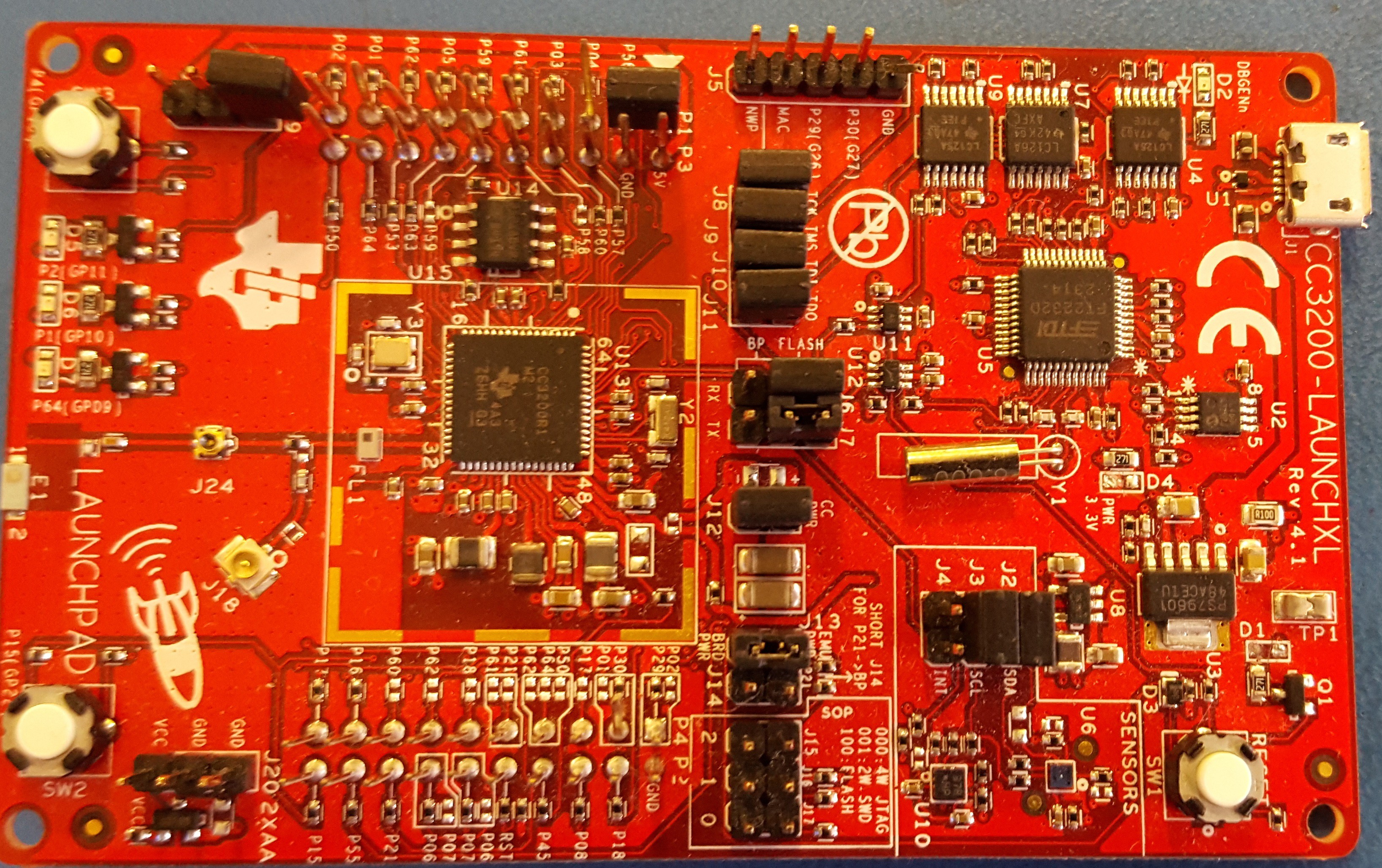
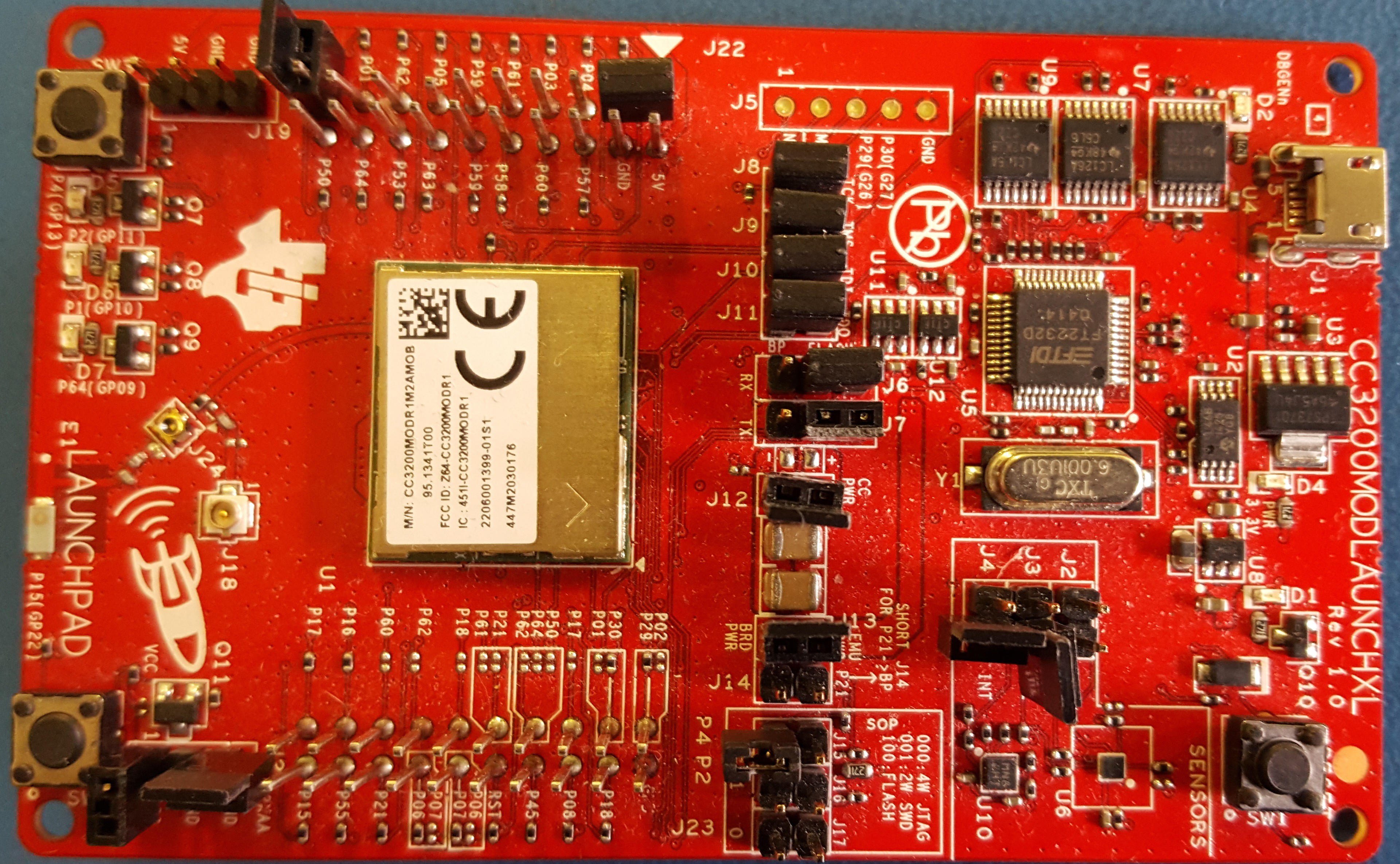
Another CC3200MOD board has arrived as well.
SimpleLink Wi-Fi CC3200 module LaunchPad
Going wireless is fun. My new toys have arrived.
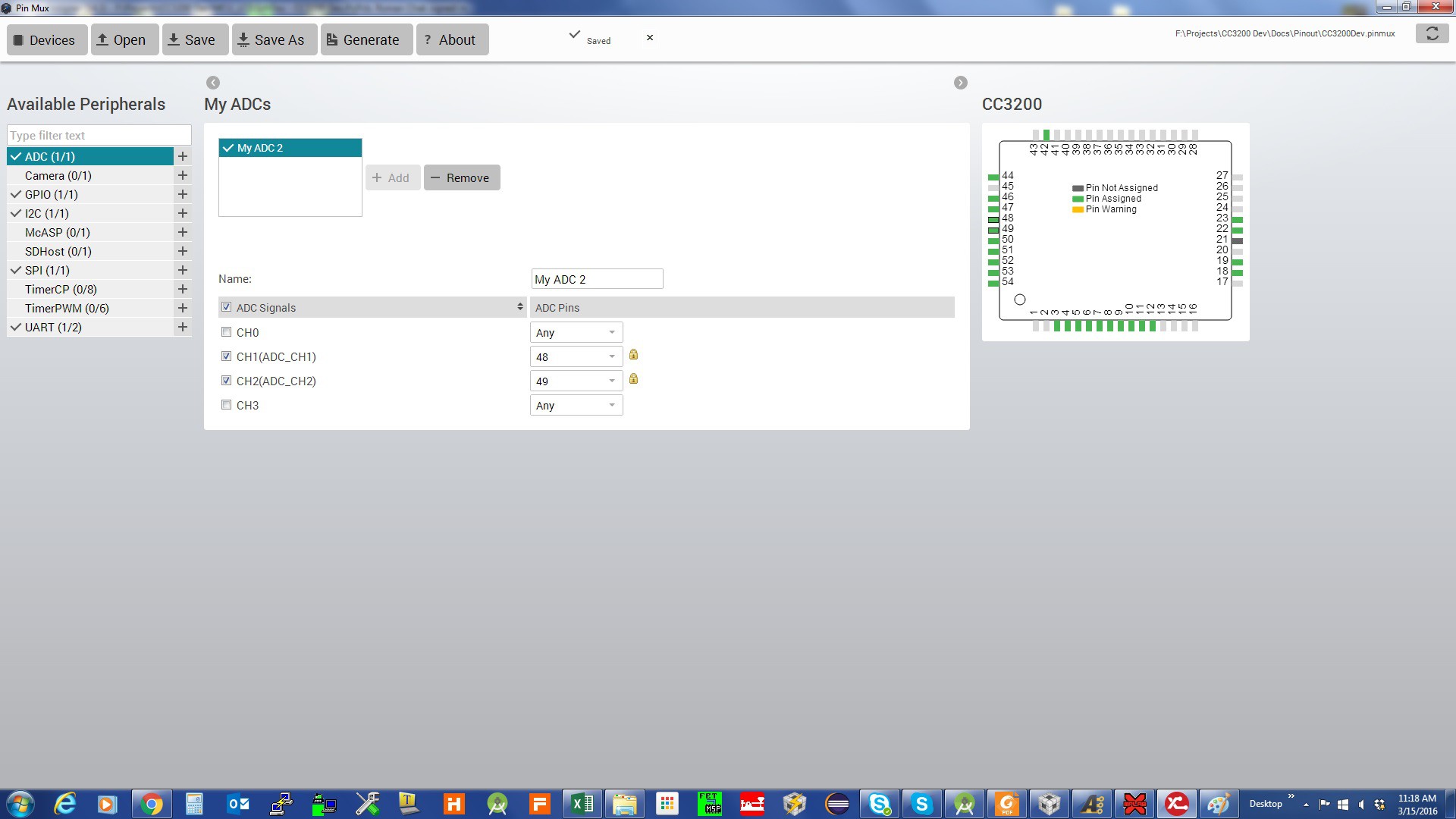
The next step is to set my pins in the code. Ti has a very handy tool for pin assignments Ti Pin Mux ToolPin Mux Tool.
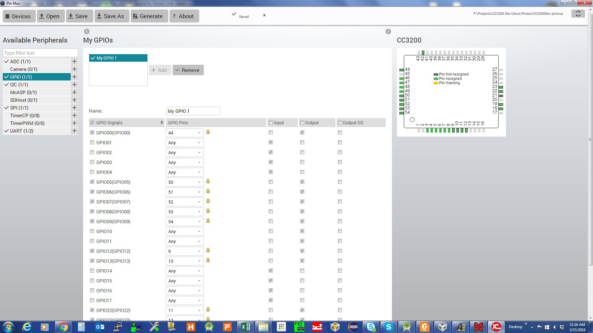
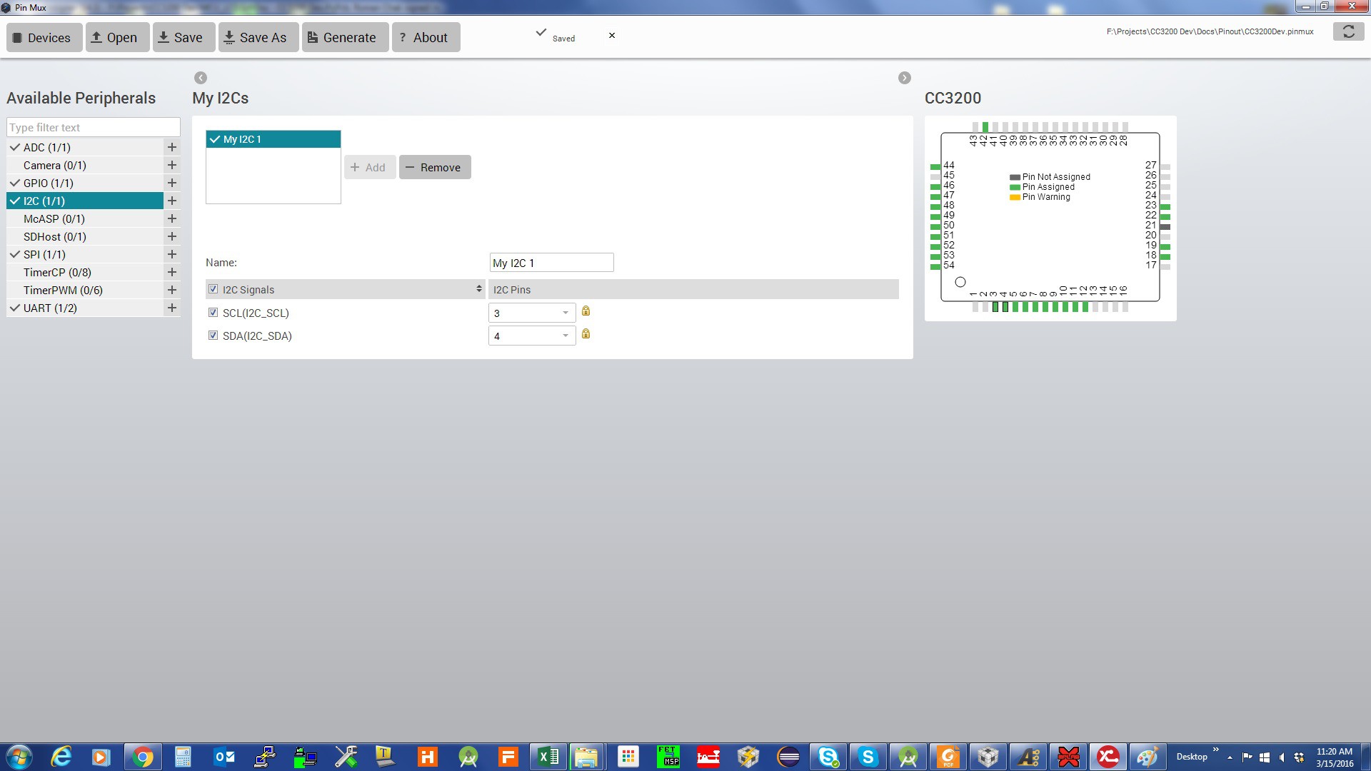
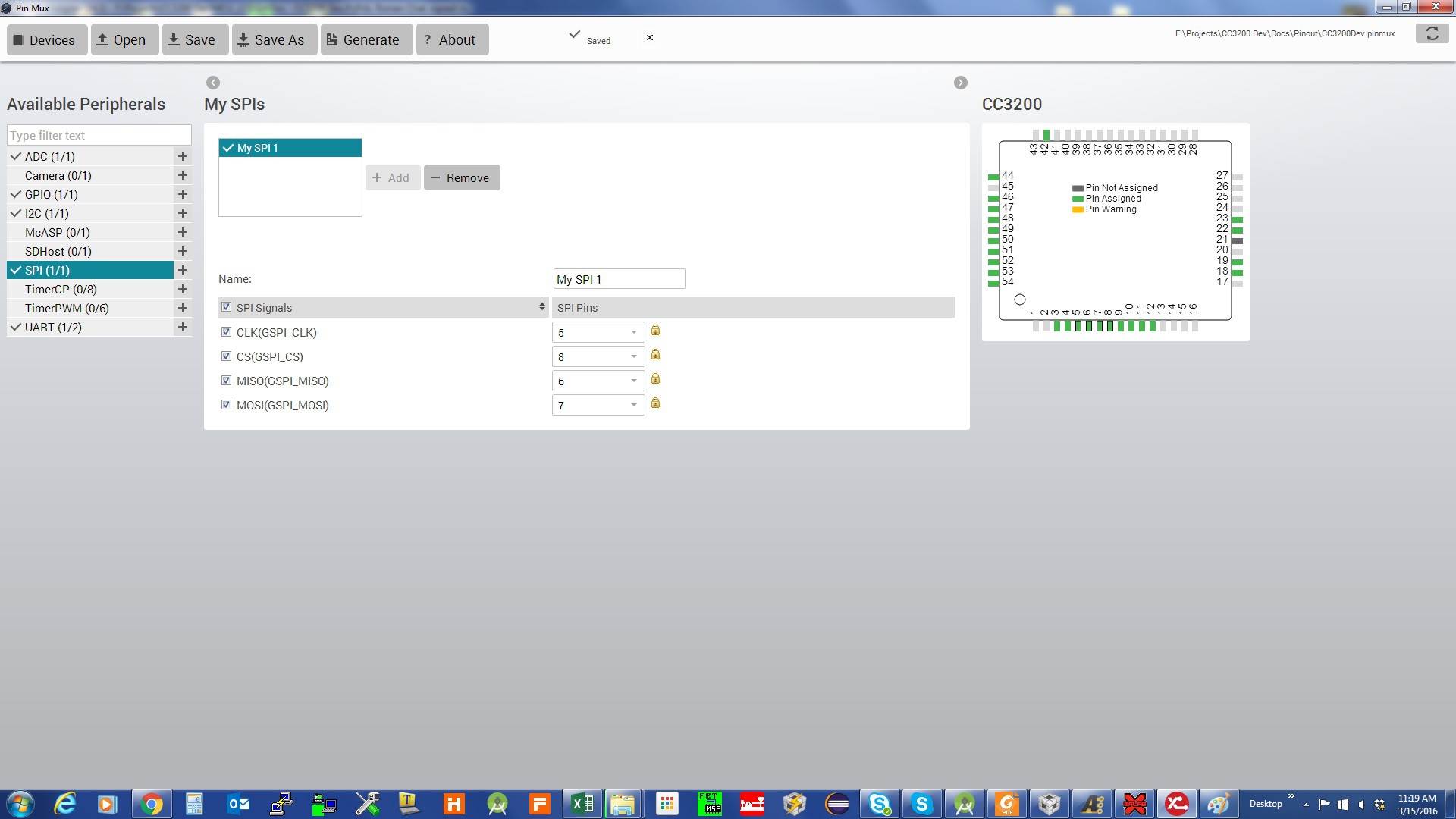
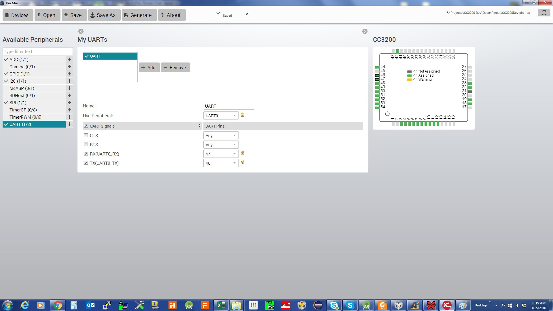
The following are screen shots of the PinMax tool for the project:
Pin assignments for GPIO:
Pin assignments for I2C:
Pin assignments for SPI:
Pin assignments for UART:
The result is:
//*****************************************************************************
// pin_mux_config.c
//
// configure the device pins for different signals
//
// Copyright (C) 2014 Texas Instruments Incorporated - http://www.ti.com/
//
//
//  Redistribution and use in source and binary forms, with or without
//  modification, are permitted provided that the following conditions
//  are met:
//
//    Redistributions of source code must retain the above copyright
//    notice, this list of conditions and the following disclaimer.
//
//    Redistributions in binary form must reproduce the above copyright
//    notice, this list of conditions and the following disclaimer in the
//    documentation and/or other materials provided with the
//    distribution.
//
//    Neither the name of Texas Instruments Incorporated nor the names of
//    its contributors may be used to endorse or promote products derived
//    from this software without specific prior written permission.
//
//  THIS SOFTWARE IS PROVIDED BY THE COPYRIGHT HOLDERS AND CONTRIBUTORS
//  "AS IS" AND ANY EXPRESS OR IMPLIED WARRANTIES, INCLUDING, BUT NOT
//  LIMITED TO, THE IMPLIED WARRANTIES OF MERCHANTABILITY AND FITNESS FOR
//  A PARTICULAR PURPOSE ARE DISCLAIMED. IN NO EVENT SHALL THE COPYRIGHT
//  OWNER OR CONTRIBUTORS BE LIABLE FOR ANY DIRECT, INDIRECT, INCIDENTAL,
//  SPECIAL, EXEMPLARY, OR CONSEQUENTIAL DAMAGES (INCLUDING, BUT NOT
//  LIMITED TO, PROCUREMENT OF SUBSTITUTE GOODS OR SERVICES; LOSS OF USE,
//  DATA, OR PROFITS; OR BUSINESS INTERRUPTION) HOWEVER CAUSED AND ON ANY
//  THEORY OF LIABILITY, WHETHER IN CONTRACT, STRICT LIABILITY, OR TORT
//  (INCLUDING NEGLIGENCE OR OTHERWISE) ARISING IN ANY WAY OUT OF THE USE
//  OF THIS SOFTWARE, EVEN IF ADVISED OF THE POSSIBILITY OF SUCH DAMAGE.
//
//*****************************************************************************

// This file was automatically generated on 3/15/2016 at 12:31:19 AM
// by TI PinMux version 3.0.625
//
//*****************************************************************************

#include "pin_mux_config.h"
#include "hw_types.h"
#include "hw_memmap.h"
#include "hw_gpio.h"
#include "pin.h"
#include "gpio.h"
#include "prcm.h"

//*****************************************************************************
void PinMuxConfig(void)
{
    //
    // Enable Peripheral Clocks
    //
    PRCMPeripheralClkEnable(PRCM_ADC, PRCM_RUN_MODE_CLK);
    PRCMPeripheralClkEnable(PRCM_UARTA0, PRCM_RUN_MODE_CLK);
    PRCMPeripheralClkEnable(PRCM_GSPI, PRCM_RUN_MODE_CLK);
    PRCMPeripheralClkEnable(PRCM_I2CA0, PRCM_RUN_MODE_CLK);
    PRCMPeripheralClkEnable(PRCM_GPIOA0, PRCM_RUN_MODE_CLK);
    PRCMPeripheralClkEnable(PRCM_GPIOA1, PRCM_RUN_MODE_CLK);
    PRCMPeripheralClkEnable(PRCM_GPIOA2, PRCM_RUN_MODE_CLK);
    PRCMPeripheralClkEnable(PRCM_GPIOA3, PRCM_RUN_MODE_CLK);

    //
    // Configure PIN_58 for ADC0 ADC_CH1
    //
    PinTypeADC(PIN_58, PIN_MODE_255);

    //
    // Configure PIN_59 for ADC0 ADC_CH2
    //
    PinTypeADC(PIN_59, PIN_MODE_255);

    //
    // Configure PIN_55 for UART0 UART0_TX
    //
    PinTypeUART(PIN_55, PIN_MODE_3);

    //
    // Configure PIN_57 for UART0 UART0_RX
    //
    PinTypeUART(PIN_57, PIN_MODE_3);

    //
    // Configure PIN_08 for SPI0 GSPI_CS
    //
    PinTypeSPI(PIN_08, PIN_MODE_7);

    //
    // Configure PIN_05 for SPI0 GSPI_CLK
    //
    PinTypeSPI(PIN_05, PIN_MODE_7);

    //
    // Configure PIN_06 for SPI0 GSPI_MISO
    //
    PinTypeSPI(PIN_06, PIN_MODE_7);

    //
    // Configure PIN_07 for...
Read more -
Simple Additive Mixer
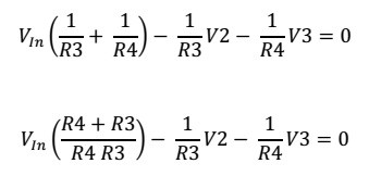
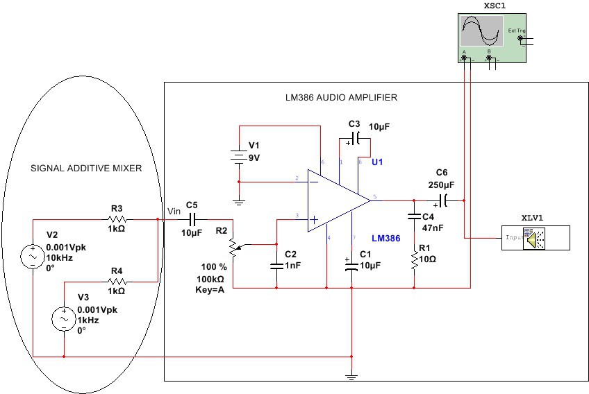
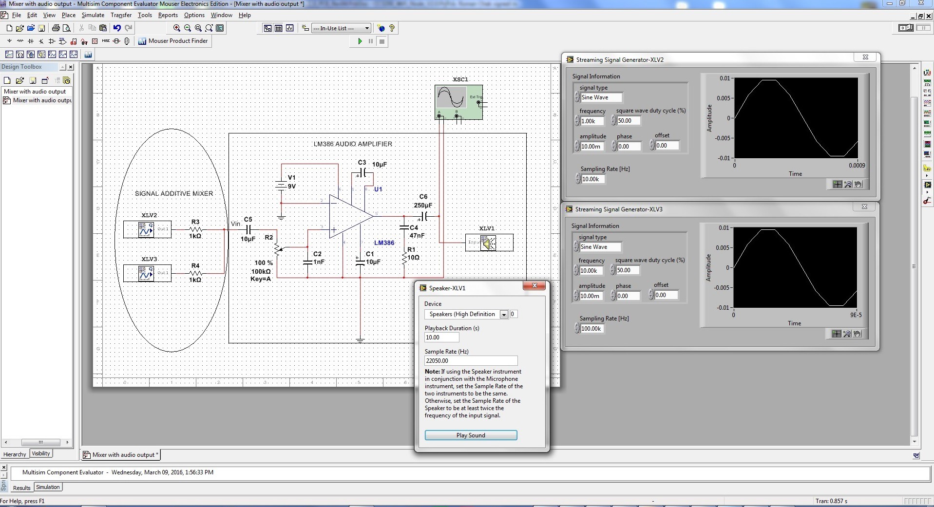
03/09/2016 at 00:22 • 0 commentsSimple additive mixers use Kirchhoff's circuit laws to add the currents of two or more signals together. When two different signals are applied to an input of an amplifier (assuming the amplifier input impedance is much higher than the source impedances of the two signal generators) they will add At Vin Junction point. Nodal analysis at Vin point gives:
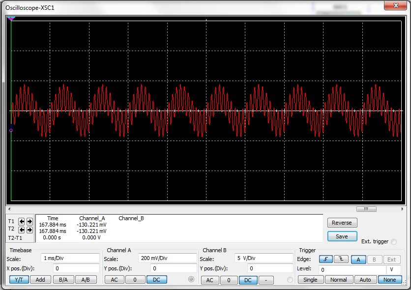
The following signal will be seen by the input of the amplifier:
Amplifier with Gain = 200
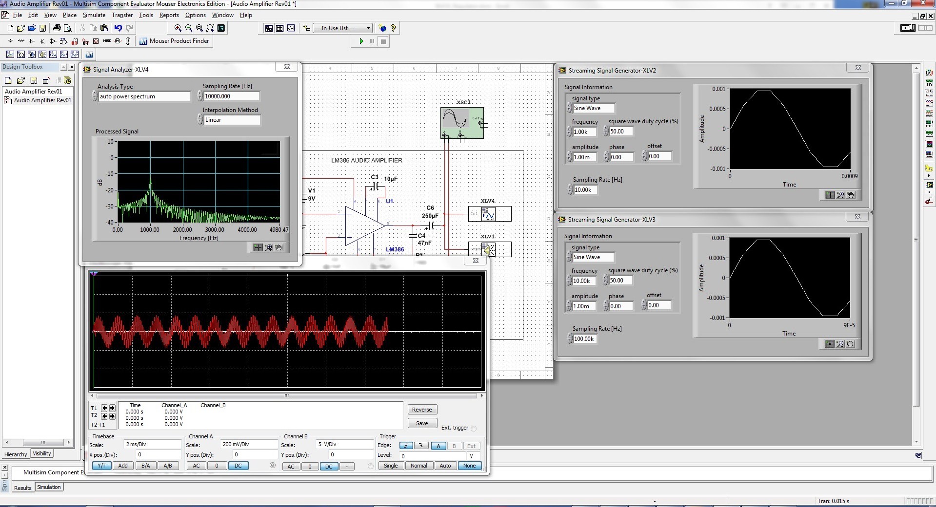
Below is the output waveform.
The following image is taken from o-scope simulation in MultisimBLUE
The simulated sound can be played on a speaker. Double click on the speaker symbol.
Use "Multisim schematics file with audio output" example below. Run the simulation for a few seconds, then press "Play sound button" and you should hear the mixed simulated sound.
Used useful links:
LM386 simulation model: http://ecee.colorado.edu/~mathys/ecen1400/Software/LM386.cir
Create LM386 in MultiSIM BLUE: http://ecee.colorado.edu/~mathys/ecen1400/Software/CreateLM386.html
Multisim schematics file with an audio output.
Used MultiSIM BLUE for simulation.
-
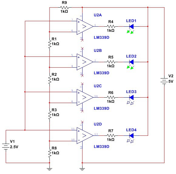
A basic volt-level indicator using LM339 comparator and a row of four LEDs.
03/03/2016 at 22:43 • 0 commentsI was going through my old files and discovered some circuits I have built some time ago. Avery basic LED voltage level indicator using LM339 can be used to indicate 4 voltage levels between 0 and 4V.
The basic circuit is shown below. Each comparator is biased one step higher than the comparator below it. As the input voltage increases and exceeds the reference voltage on the comparator's inverting input, the output goes high and lights its respective LED. Output sink current for the LEDs is approximately 6mA. It can be extended to 8 levels with an additional LM339 comparator. The circuit was simulated with MultiSIM BLUE.
-
A short note on the differential input (hacking into the analog).
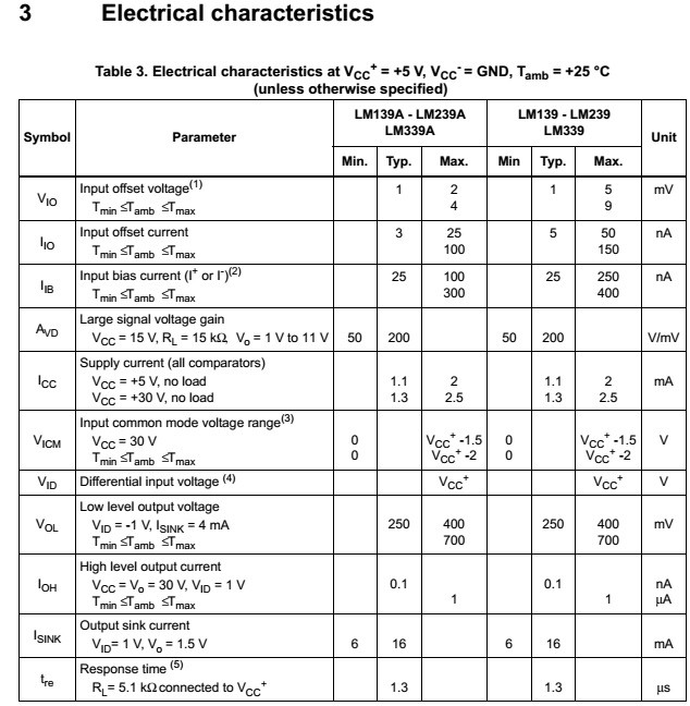
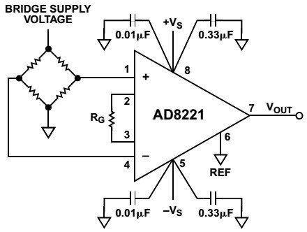
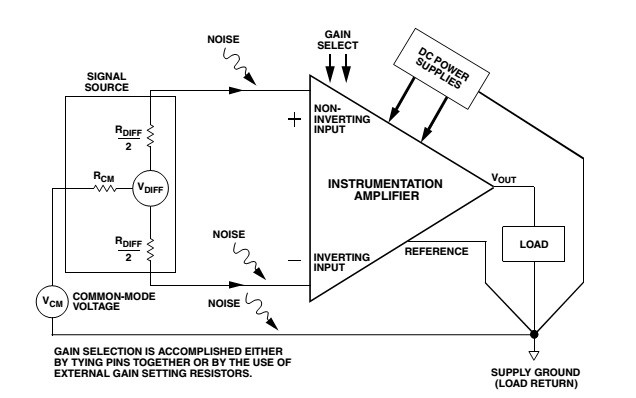
02/18/2016 at 19:42 • 0 commentsThe main component of the analog front is an instrumentation amplifier. An instrumentation amplifier is a closed-loop gain block that has a differential input and an output that is single-ended with respect to a reference terminal. Most commonly, the impedances of the two input terminals are balanced and have high values, typically 109 Ohm, or greater. The input bias currents should also be low, typically 1 nA to 50 nA. As with op amps, output impedance is very low, nominally only a few milliohms, at low frequencies. An in-amp employs an internal feedback resistor network that is isolated from its signal input terminals. The following figure shows a resistor bridge preamp circuit. When sensing a signal, the bridge resistor values change, unbalancing the bridge and causing a change in differential voltage across the bridge.
The signal output of the bridge is this differential voltage, which connects directly to the in-amp’s inputs.
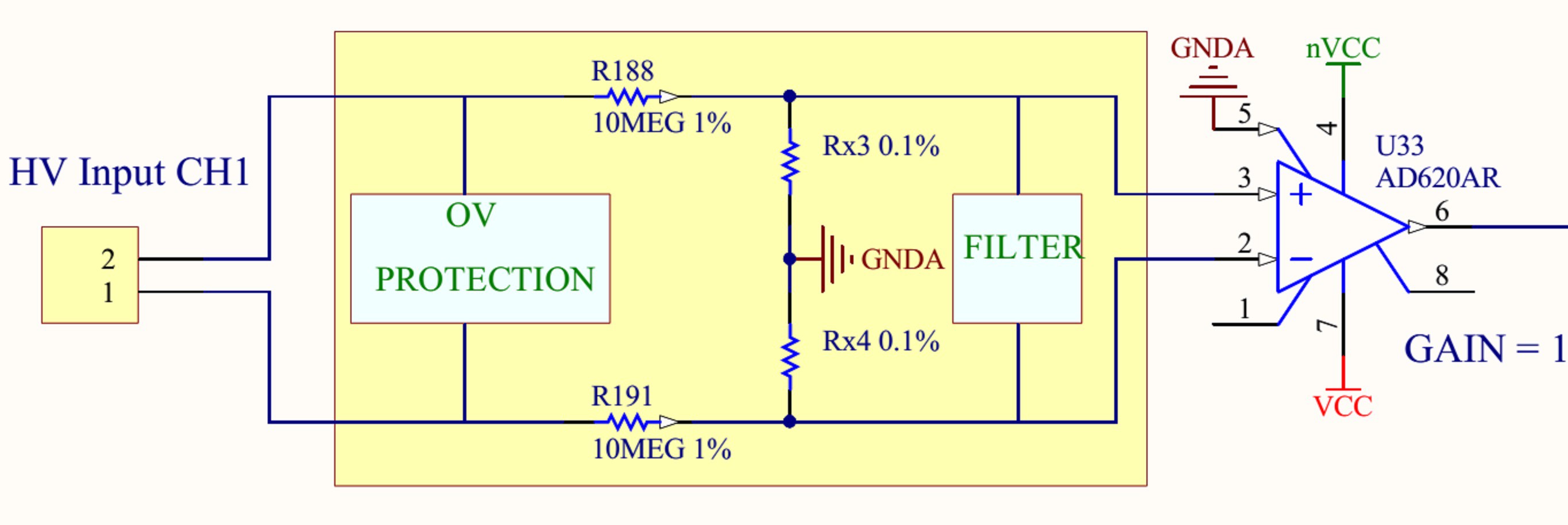
The following figure is the differential input into the multi-meter. The input signal is conditioned, reduced in amplitude by the input divider then applied to the instrumentation amplifier.
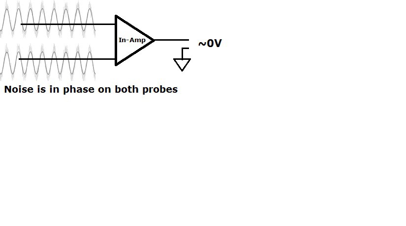
HV Input is physically connected to the handheld test probes. Voltage is measured in the differential mode (potential difference between positive and negative probes) with U33 (AD620A). The in-amp will normally reject the common-mode dc voltage, or any other voltage common to both lines, while amplifying the differential signal voltage, the difference in voltage between the two lines. Instrumentation amplifiers are very effective in extracting weak signals in the presence of background noise. The handheld test leads are basically long wires with probes. They will act as wire antennas that couple well into 60 Hz AC interference generating 60 Hz voltage on both leads. The good thing is that both of the leads generate in phase voltage that appears as common mode input to the In Amp. In Amp is designed to reject these kind of signals.
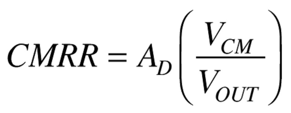
Common-mode rejection (CMR), the property of canceling out any signals that are common (the same potential on both inputs), while amplifying any signals that are differential (a potential difference between the inputs), is the most important function an instrumentation amplifier provides. Both dc and ac common-mode rejection are important in amp specifications. Any errors due to dc common-mode voltage (i.e., dc voltage present at both inputs) will be reduced 80 dB to 120 dB by any modern in-amp of decent quality.
AD – is the differential or normal mode gain. The gain between input and output for voltages applied
differentially (or across) the two inputs.CMR = 20 log10 CMRR.
An in-amp needs to be able to amplify microvolt-level signals while rejecting common-mode voltage at its inputs.
Since an ideal instrumentation amplifier detects only the difference in voltage between its inputs, any common mode signals (equal potentials for both inputs), such as noise or voltage drops in ground lines, are rejected at the input stage without being amplified.
All mentioned above is the main reason why I used instrumentation amplifiers in the handheld unit.
You can find more about instrumentational amplifiers in “A Designer’s Guide to Instrumentation Amplifiers” published by Analog Devices.

