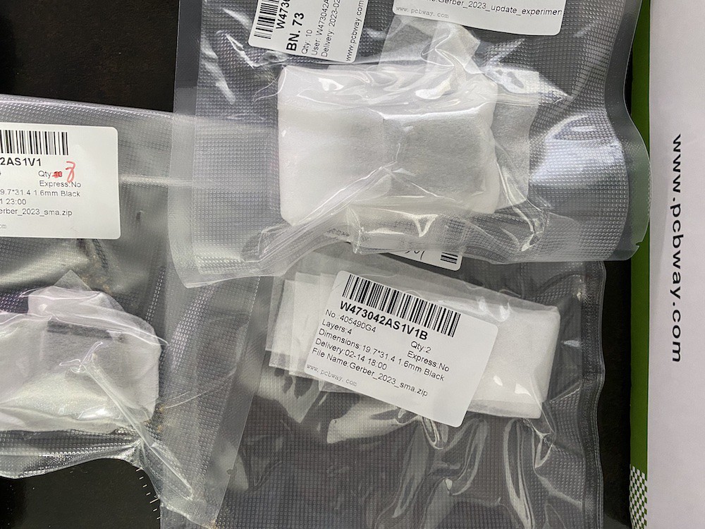
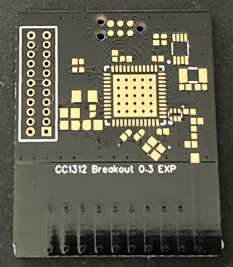
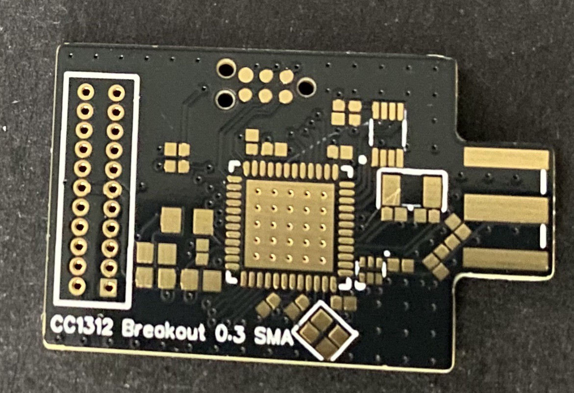
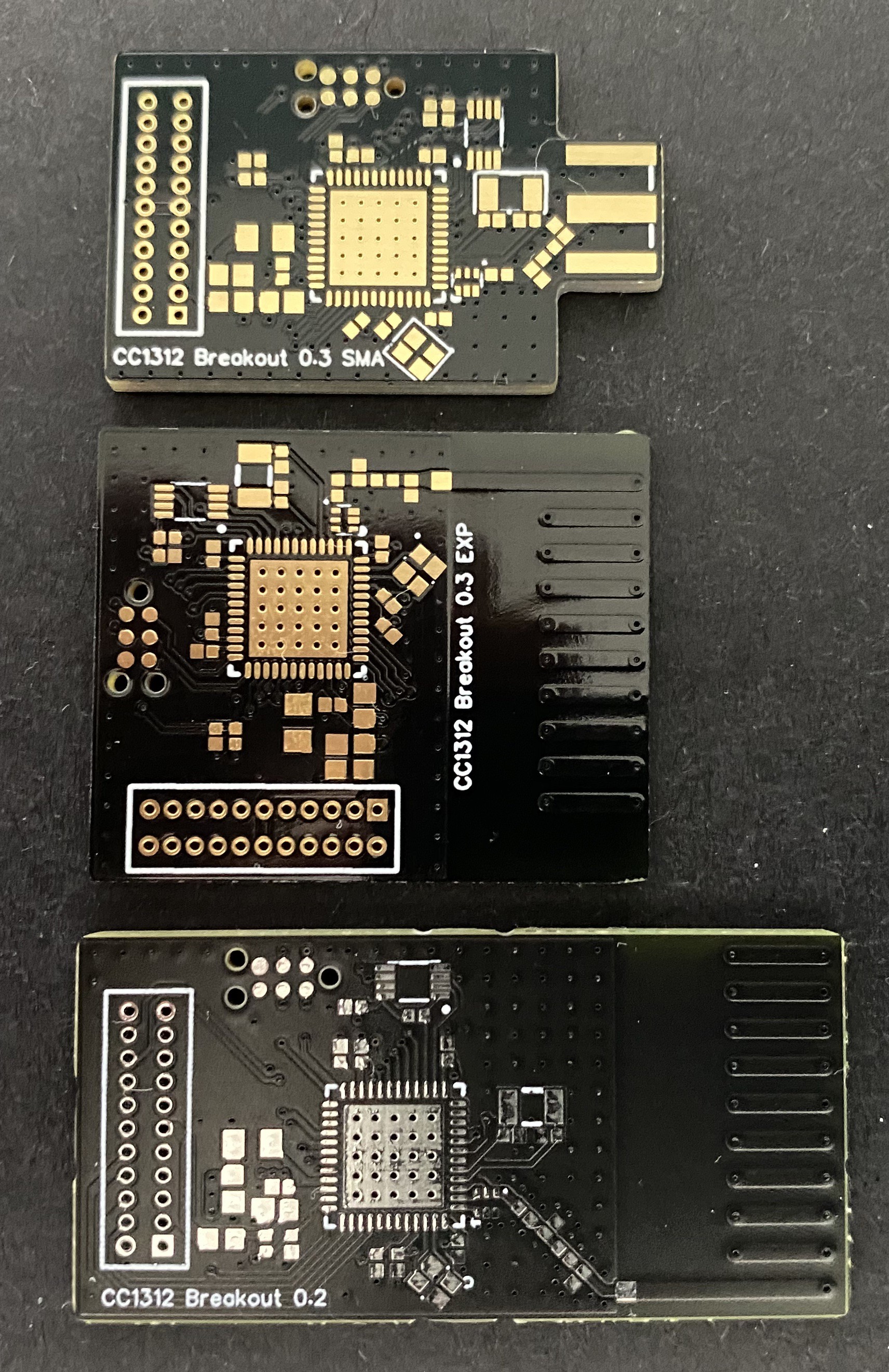
Having just received my new radio board design from PCBWay, it was time to match the antenna and test performance. Here, I will be focusing on the PCB Antenna board:
To get good radio performance, one needs to match the antenna impedance to that of the source. I use Carey Wang's excellent xavna to characterize the PCB antenna. The idea is to use a VNA to calculate what kind of filter is needed to bring the antenna's impedance (as seen from the transciever) as close to 50 Ohm as possible at the desired frequency. I leave footprints for 0402 passives to accomodate the filter, consisting of capacitor/inductor combinations.
Step 1 is to attach a semi-rigid coaxial cable to a board just before the antenna, and measure its characteristic impedance with the VNA (shown below for a 2.4 GHz/Sub-G version of the board):
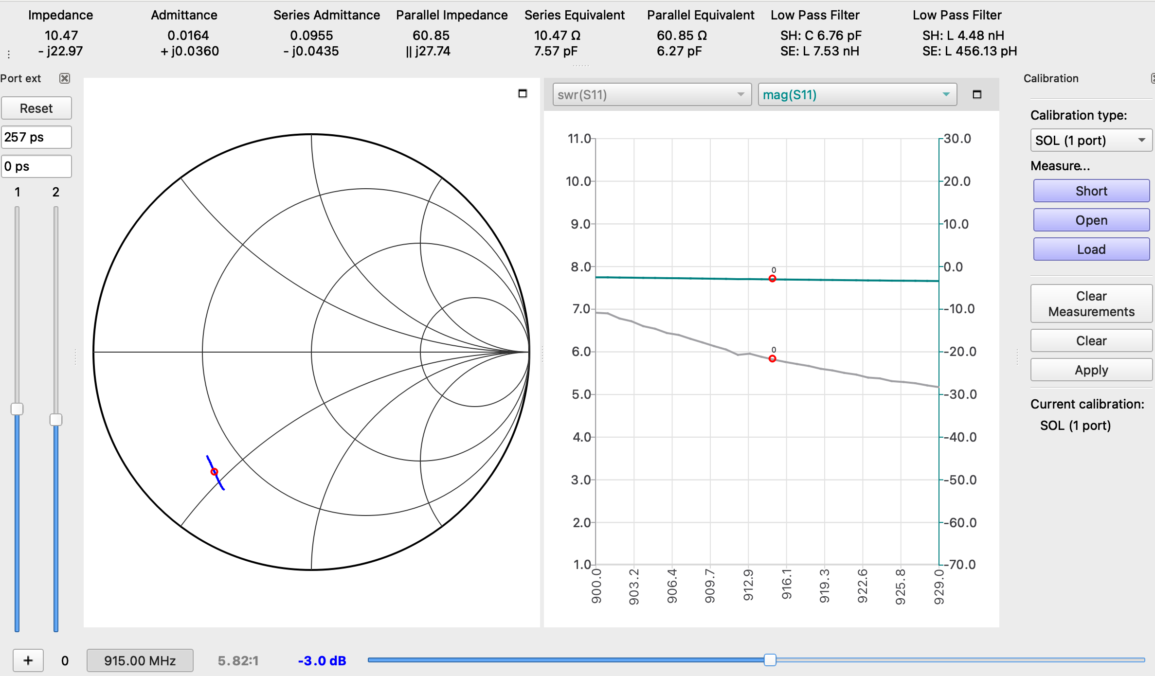
Step 2, take a measurement of the antenna without any filtering. This is the result for my new compact PCBWay board:
On the Smith Chart above, the center of the circle represents our target impedance. Here, I chose to measure the response of the antenna from 900 to 930 MHz, which is represented by the blue line. We're fairly far from our target, so definitely need to add some filtering.
I modified the software for the xavna to simplify this step: the upper right corner shows what value components to use to get a match. There are two possibilities, either a 6.76 pF shunt capacitor and 7.53 nH series inductor, or a 4.48 nH shunt inductor followed by a 456 pH series inductor.
Step 3, finding closely matching components. I use Kemet RF capacitors and Johanson RF inductors for that purpose. The theoretical values are rarely what is actually needed, and I ultimately settled on a 5 pF shunt capacitor and 10 nH series inductor, which resulted in an OK match. Another modification I made to the software is a display of "SWR" (standing wave ratio), the grey curve shown to the right of the Smith chart. This represents the amount of power reflected back from the antenna. A good match is attained when SWR is below 2:1. Here, we're getting 1.18:1 at 915 MHz, which isn't too bad.
Next, it's time to test actual radio performance! I start with TI's SmartRF Studio. First, let's see how low the noise floor is:
Around -115 dBm, not bad! This actually compares favorably to TI's LaunchPad, which is hovering around -100 dBm in the same conditions. This means we have a little more "link budget", which should result in longer range.
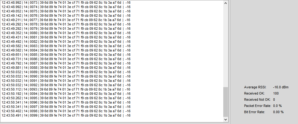
Next, let's see transmit and receive performance (using a TI launchpad at the other end). Receiving packets, both boards in the same room yields -16 dBm, that's awesome! My old design was at -19 dBm in these conditions, so that's a great improvement.
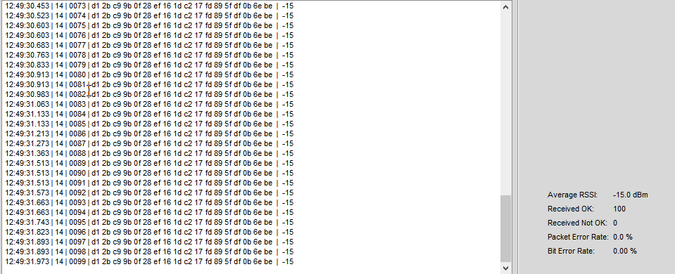
...and transmitting, -15dBm vs -16 for the old board. The PCBWay board performs better in all respects!
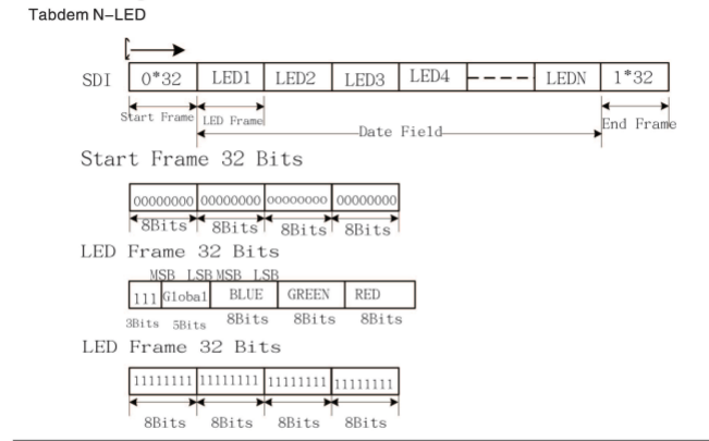
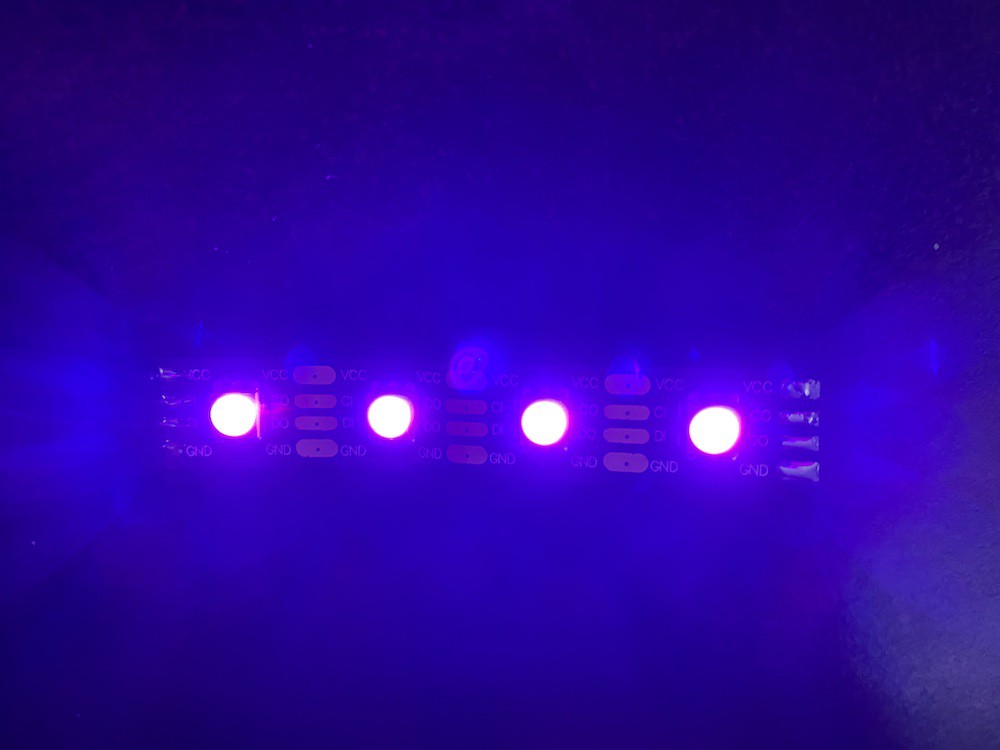
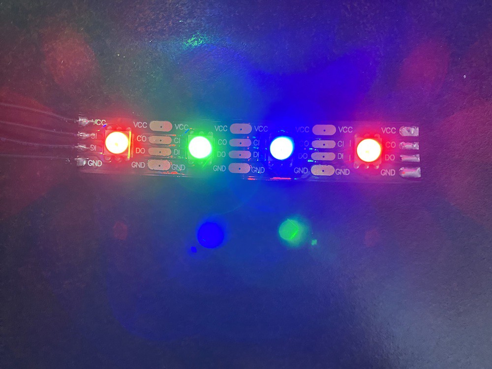
Did some tests with APA102C RGB LEDs. These theoretically work above 4.5V, but I was successful providing 3.3V for both signal and VCC, so no level shifting necessary ...at least with the batch I have! Another thing that doesn't appear to be necessary is the end frame specified in the datasheet.
If you look at the end frame, it would look like a fully lit extra LED after N LEDs. I've actually found that this is exactly what happens (eg, if you output data for 32 LEDs and add the end frame, you get a 33rd white LED, probably not what you want). I've removed the end frame from my driver, and everything else behaves as expected.
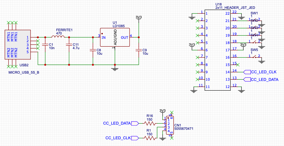
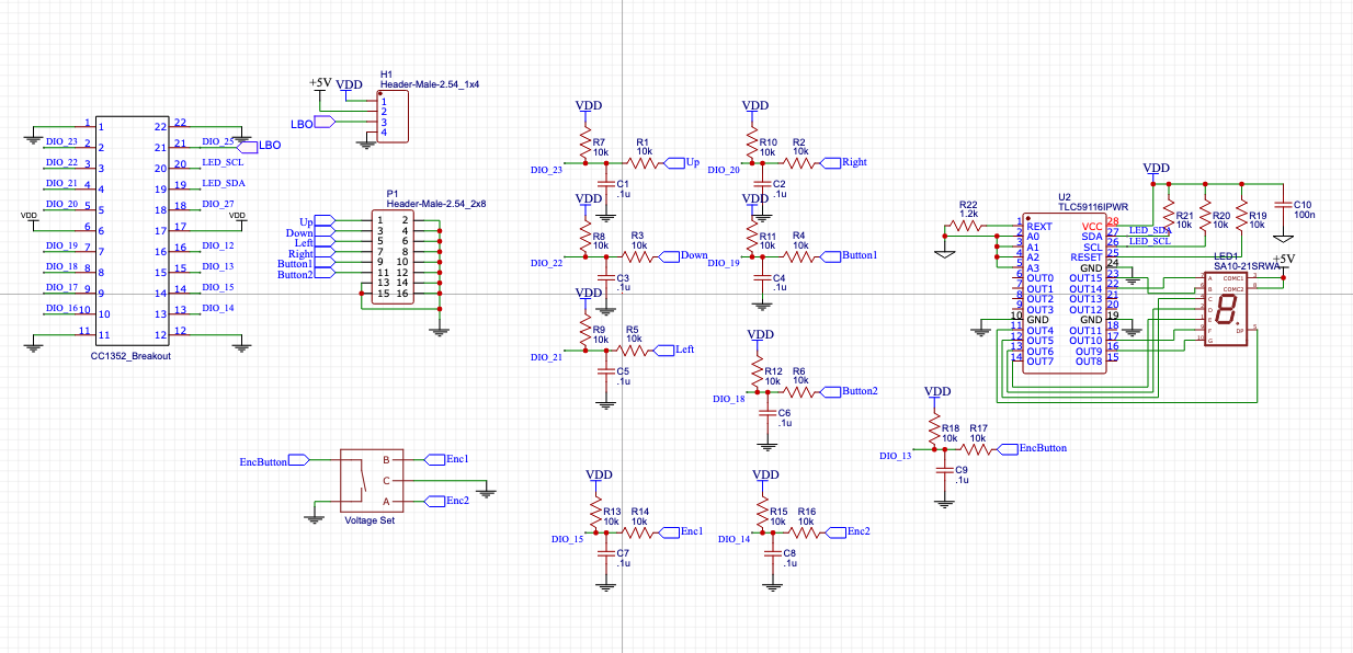
Ultra-simple circuit for use with these guys, with provisions for use without a wireless MCU with tactile switches for mode changes:
This project falls in the "can I just get this working" category. No real intention of making it "nice", or even using it...!
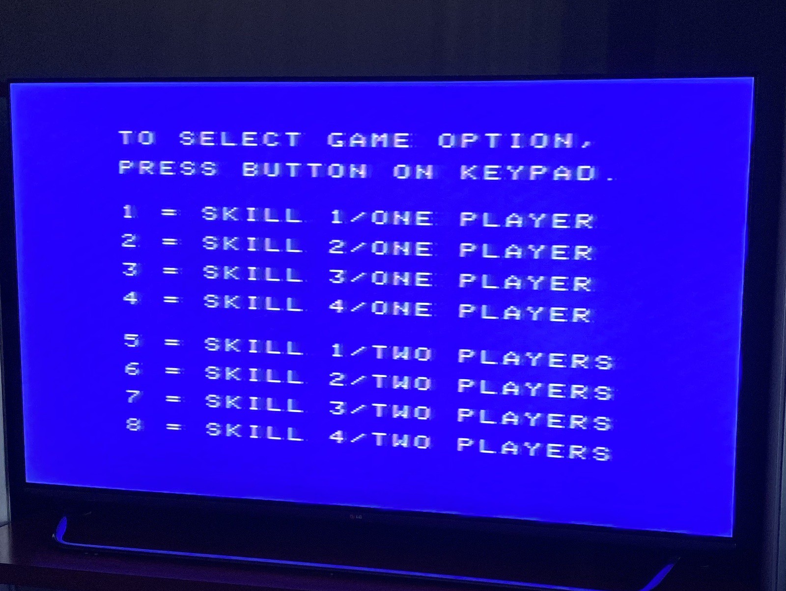
A while ago, I recovered my childhood ColecoVision from storage in a barn. It had been sitting there for a few decades, along with a some game cartridges. Let's just say it wasn't in the greatest of shapes! The following had to be fixed to get the console running:
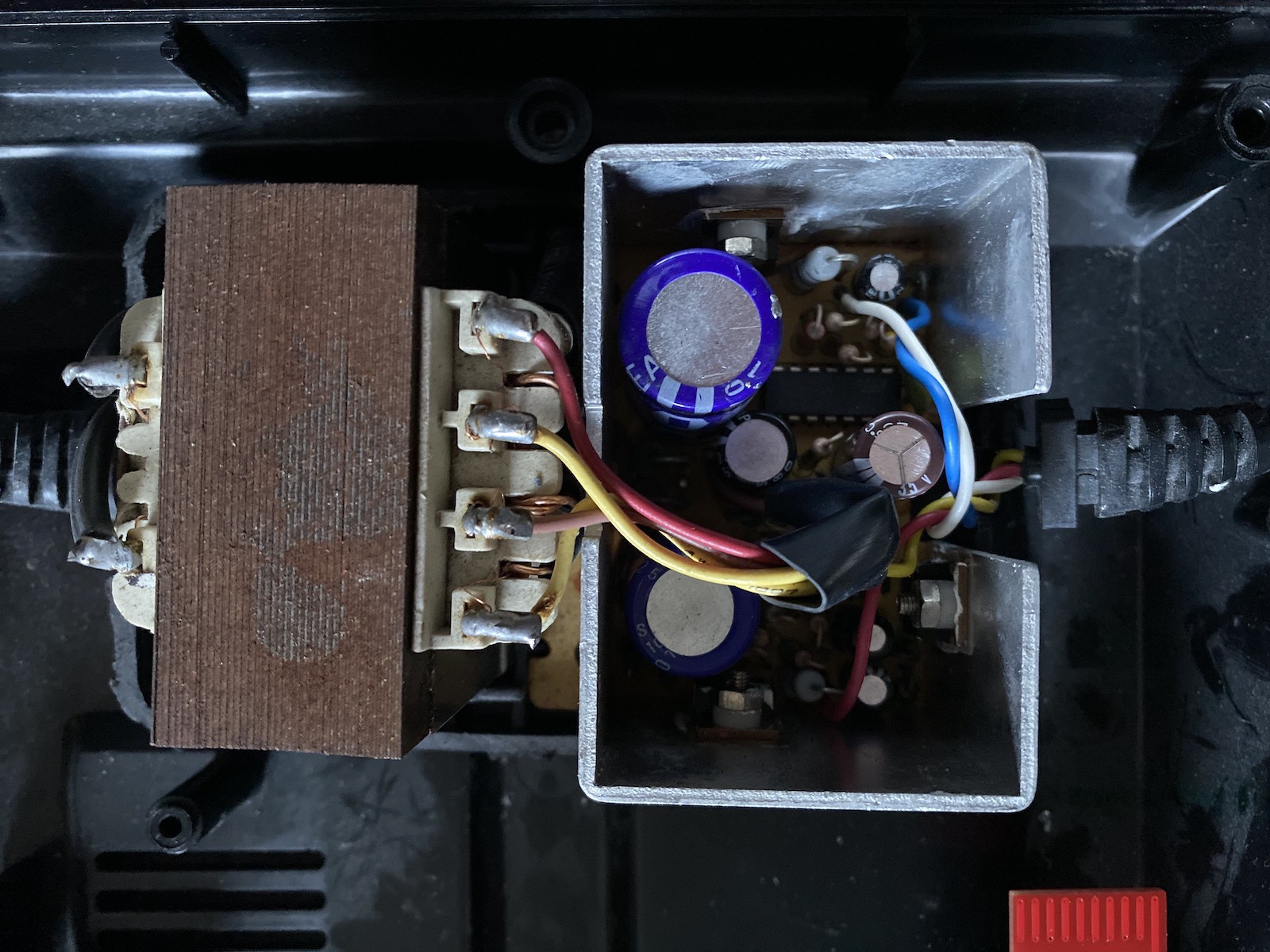
Power supply 5V rail not working. Fixed by replacing faulty ceramic cap somewhere in the power brick (this is a destructive process, since the brick is ultrasonically welded shut):
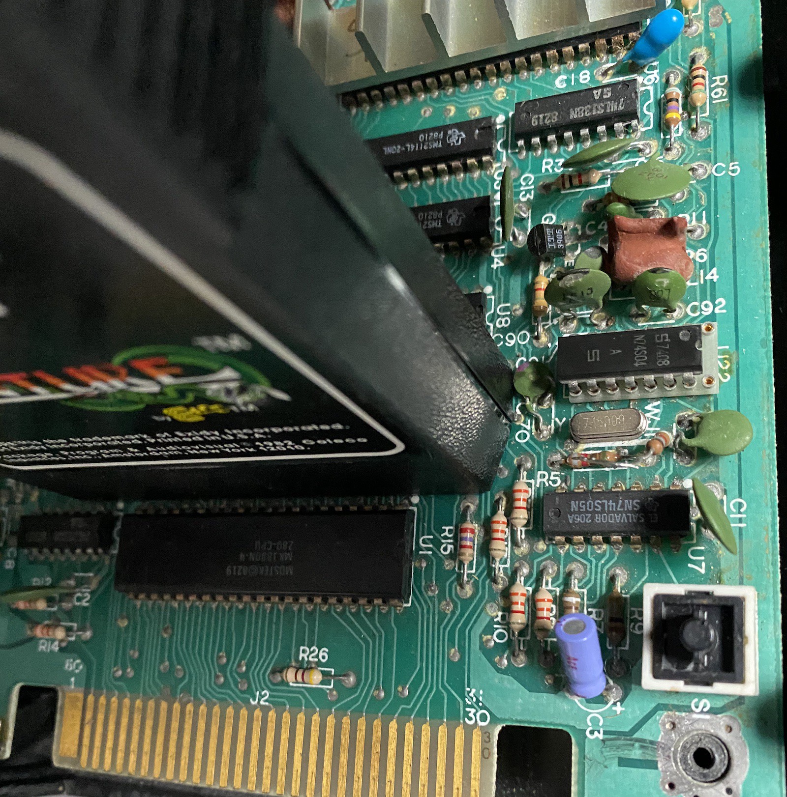
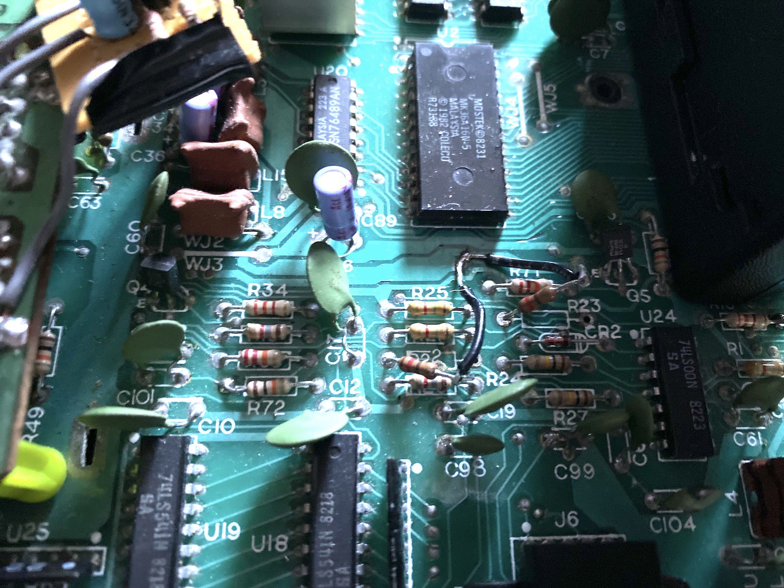
Clock crystal leg corroded away. Found a 7.159 MHz crystal on eBay, and (partially!) removed resistor bodge from original console
7404 chip legs corroded away (replaced as well)
Next, I had to modify the output section to get a composite signal out (instead of RF modulation), using Ben Heck's hack.
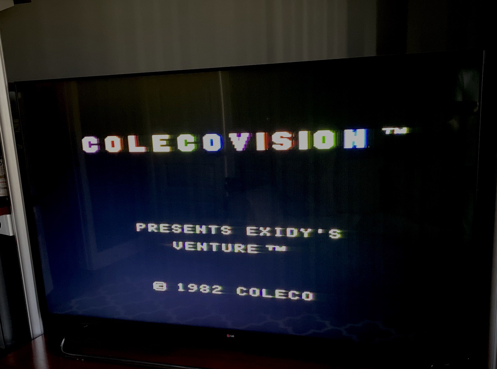
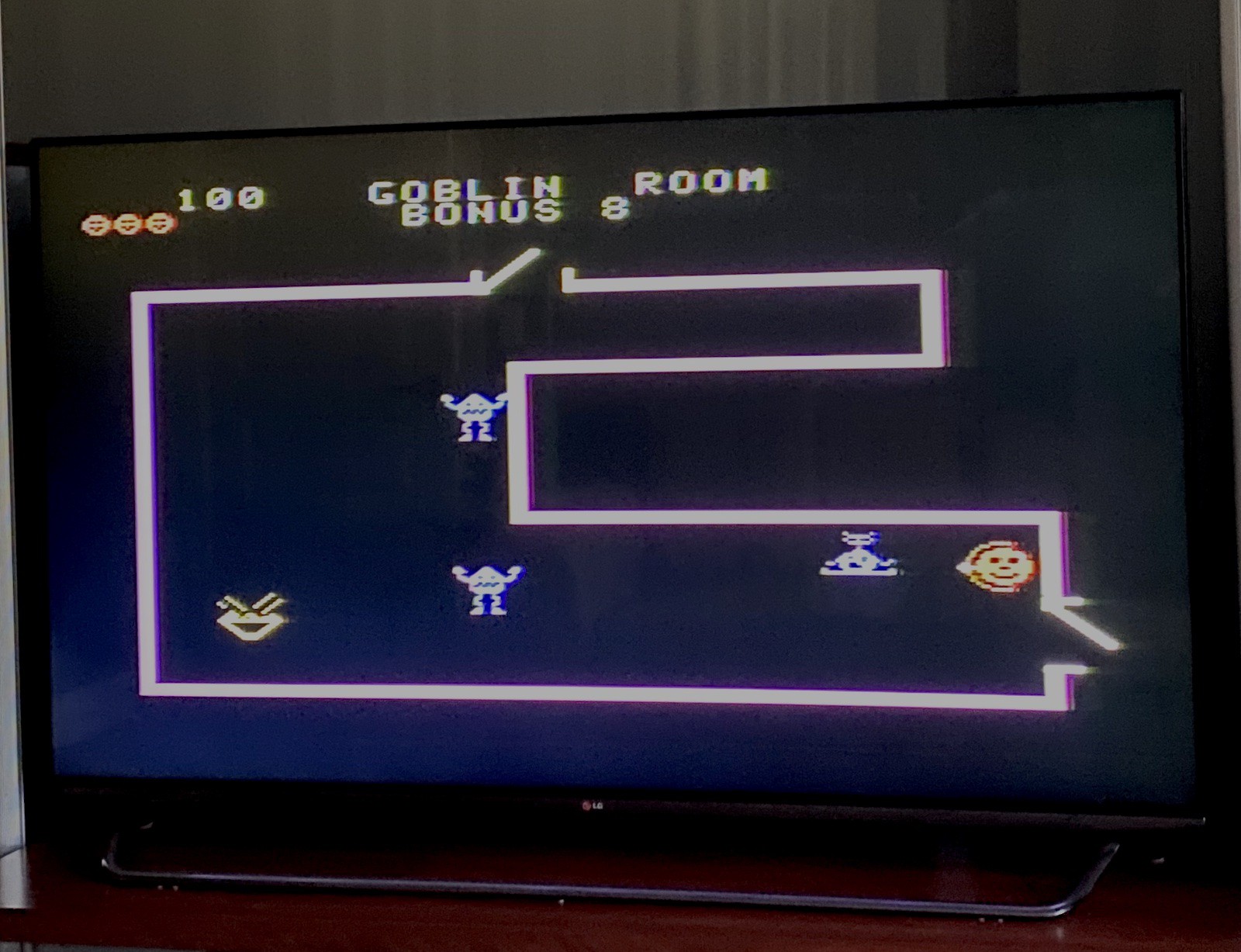
Great, we have a working console with video out!
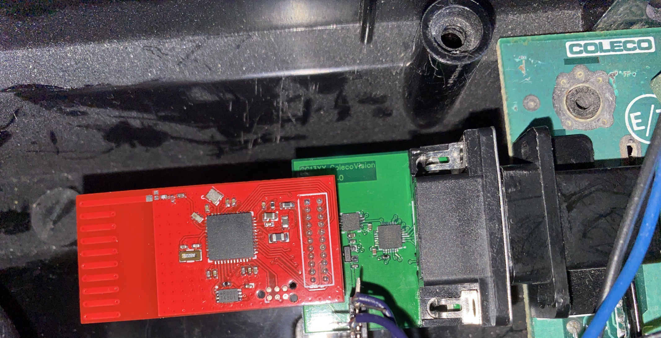
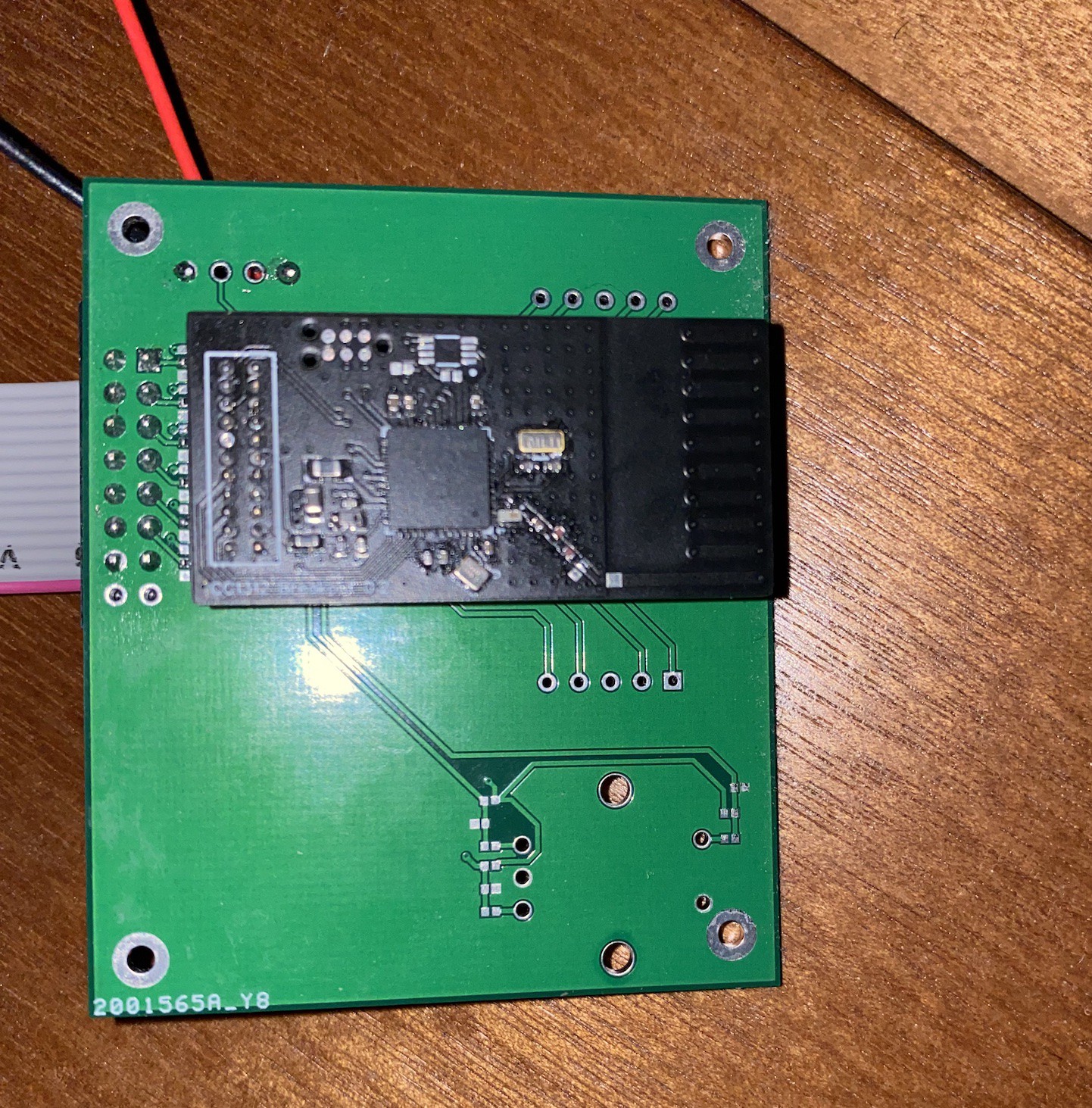
Unfortunately (fortunately?!), none of the recovered controllers could be repaired, due to excessive corrosion and crud. I thought it would be cool to reuse the 802.15.4 boards I use for my main projects and create a wireless controller. To that end, I designed a couple of host boards, one for the joystick itself, a pretty simple GPIO board, with allowances for an encoder and numeric display to simulate the CV's keypad (didn't actually bother with the encoder and display, in the end):
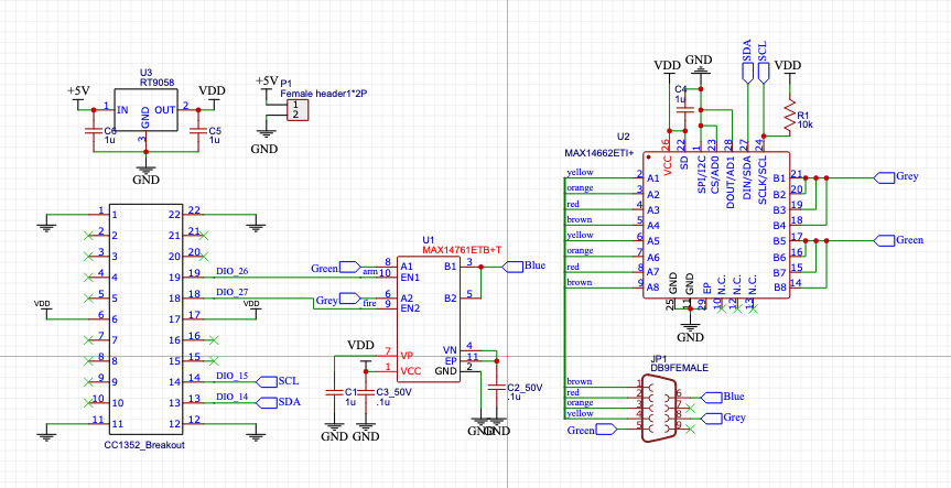
The cool part is on the receiver end, where I ended up using digital switches (MAX14662 and MAX14761) to simulate the original Joystick inputs. Wasn't sure this was going to work (especially since I didn't bother with diodes), but it did!
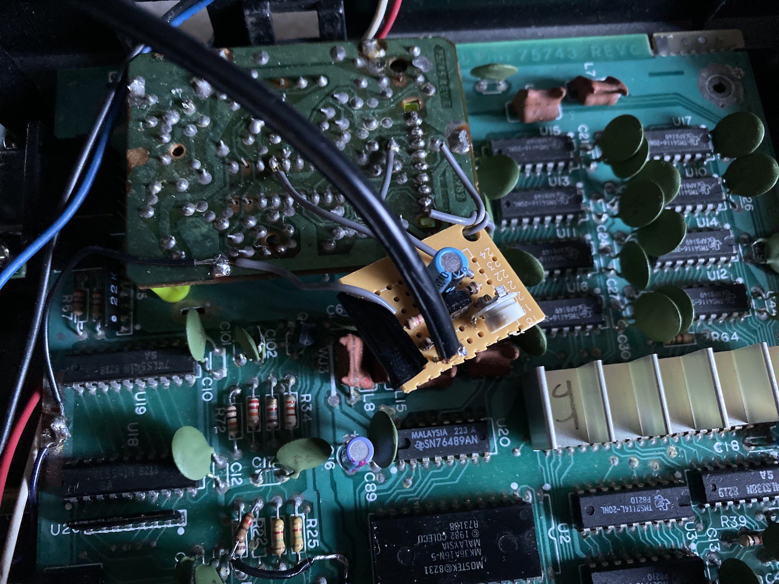
I didn't want to spend too much time with the keypad stuff, so I hacked the console a little to bypass the built-in keypad/joystick toggle. The mod just provides ground to both types of inputs at all times. Joystick pins are pulled high to 2.5V, and inputs are detected when one of the pins is brought low. This way, the joystick can partially simulate keypad presses (eg, joystick right = keypad press 1). Here, I bypass the circuitry by grounding two resistors:
Having gained a better understanding of the controller circuitry, it seems I could have simplified the emulator a great deal (avoiding the need for digital switches completely in favor of plain GPIOs). If anyone knows why the original ColecoVision designers used -5V (as opposed to ground) on the 74LS00 for keypad/joystick toggle, I'd love to know.
As stated, this is only a "make it work" project, so please forgive the crudity of everything shown here!
In the end, everything worked really well. Below, the receiver end, transmitter and the "arcade" joystick I slapped together from spare MDF.
I'd be happy to discuss this with any real ColecoVision fans looking to implement something similar, but that's it for now!