-
SN76489 programmable sound generator
06/26/2026 at 07:32 • 0 commentsSN76489 programmable sound generator using VHDL and CPP
![]()
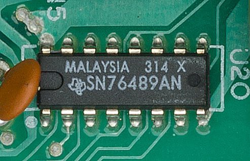
SN76489-DIP16 ![]()
![]()
Texas Instruments SN76489 - Wikipedia
SN76489 Complex Sound Generator
VHDL, BSD 3-Clause
A huge amount of effort has gone into making this core as accurate as possible to the real IC, while at the same time making it usable in all digital SoC designs, i.e. retro-computer and game systems, etc. Design elements from the real IC were used and implemented when possible, with any work-around or changes noted along with the reasons.
Synthesized and FPGA proven:
- Xilinx Spartan-6 LX16, SoC 21.477MHz system clock, 3.58MHz clock-enable.
References:
- The SN76489 datasheet
- Insight gained from the AY-3-8910/YM-2149 die-shot and reverse-engineered schematics (similar audio chips from the same era).
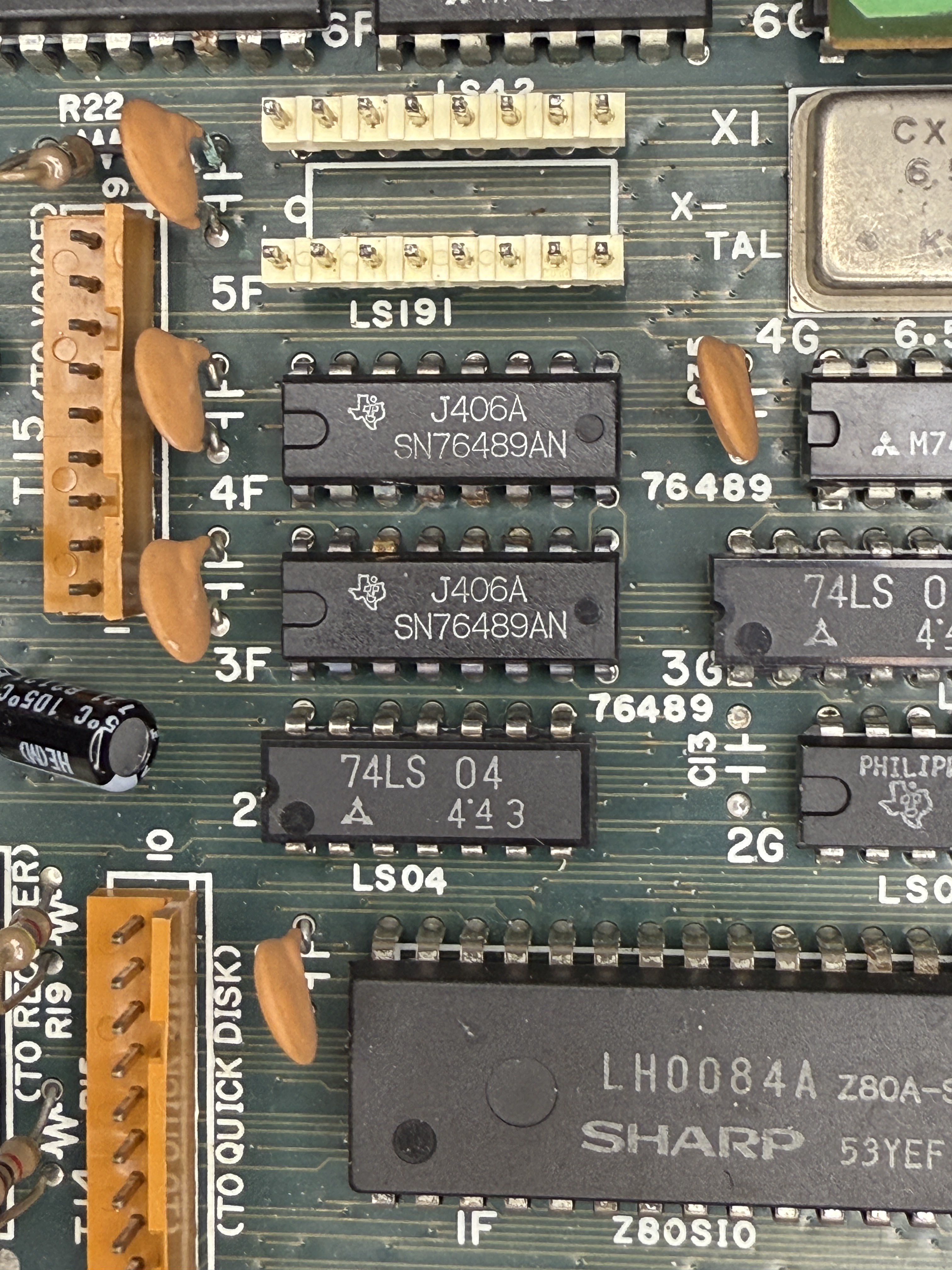
- Real hardware (SN76489 in a ColecoVision game console).
- Chip quirks, use, and abuse details from friends and retro enthusiasts.
Generates:
- Unsigned 12-bit output for each channel.
- Unsigned 14-bit summation of the four channels.
- Signed 14-bit PCM summation of the four channels, with each channel converted to -/+ zero-centered level or -/+ full-range level.
The tone counters are period-limited to prevent the very high frequency outputs that the original IC is capable of producing. Frequencies above 20KHz cause problems in all-digital systems with sampling rates around 44.1KHz to 48KHz. The primary use of these high frequencies was as a carrier for amplitude modulated (AM) audio. The high frequency would be filtered out by external electronics, leaving only the low frequency audio.
When the tone counters are limited, the output square-wave is disabled, but the amplitude can still be changed, which allows the A.M. technique to still work in a digital Soc.
I/O requires at least two clock-enable cycles. This could be modified to operate faster, i.e. based on the input-clock directly. All inputs are registered at the system-clock rate.
Optionally simulates the original 32-clock (clock-enable) I/O cycle.
The SN76489 does not have an external reset and the original IC "wakes up" generating a tone. This implementation sets the default output level to full attenuation (silent output). If the original functionality is desired, modify the channel period and level register initial values.
Basic I/O interface use:
- Set-up data on data_i.
- Set ce_n_i and wr_n_i low.
- Observe ready_o and wait for it to become high.
- Set wr_n_i high, if done writing to the chip set ce_n_i high.
SN76489 Complex Sound Generator
TDSN76489
SN76489 implementation for Teensyduino Audio Library
Information regarding the implementation of the Sega Master System's variant of the SN76489 can be found at: http://www.smspower.org/Development/SN76489
Example sketches in this library use VGM files to test the SN76489. VGM files for Master System are commonly found in compressed format (7z) on the web. To use them with this libary you will need to extract them:
Linux users:
7za -e %vgmfile>#/p###
Afterwards, if you wish to generate a header file which can be included in a project:
xxd --include %extractedvgmfile% &> %file>#/p###
Windows users: ask google
TDSN76489
-
Backup OSCCAL
05/25/2026 at 14:04 • 0 commentsThis document includes the programming specifications for the following devices:
• PIC10F200
• PIC10F202
• PIC10F204
• PIC10F206MEMORY MAPPING
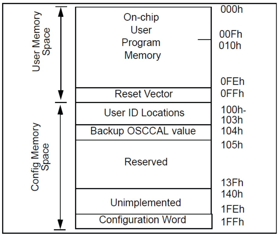
User Program Memory Map
The user memory space extends from (0x000-0x0FF) on the PIC10F200/204 and (0x000-0x1FF) on the PIC10F202/206. In Program/Verify mode, the program memory space extends from (0x000-0x1FF) for the PIC10F200/204 and (0x000-0x3FF) for the PIC10F202/206. The first half, (0x000-0x0FF) and (0x000-0x1FF) respectively, is user program memory. The second half, (0x100-0x1FF) and (0x200-0x3FF) respectively, is configuration memory. The PC will
increment from (0x000-0x0FF) and (0x000-0x1FF) respectively, then to 0x100 and 0x200, respectively (not to 0x000).
In the configuration memory space, 0x100-0x13F for the PIC10F200/204, and 0x200-0x23F for the PIC10F202/206, are physically implemented. However, only locations 0x100-0x103 and 0x200-0x203 are available. Other locations are reserved.![]()
PIC10F200/204 PROGRAM MEMORY MAP HOW TO VIEW THE BACKUP OSCCAL?
The memory locations 0x0100-0x103 are used for User ID Locations. The backup value of the OSCCAL value is located at 0x0104.
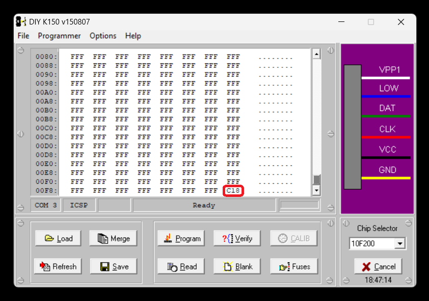
Take any fresh PIC10F200 and read the content normally.
![]()
We can see the final location of the FLASH memory contains the OSCCAL value of 0xC18
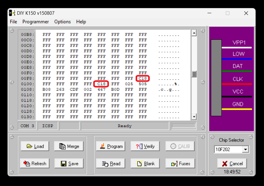
Now set the device as PIC10F202. By this way the programmer able to access the higher memory locations.
![]()
In the above view please note the selected chip is PIC10F202. But the actual chip we used is PIC10F200. At the memory location 0x0104 we can see the same OSCCAL value which in this chip is 0xC18.
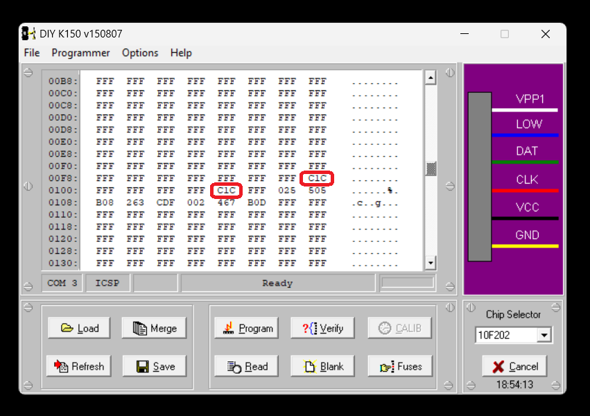
Below is the screen view for one more PIC10F200 chip
![]()
In the above case the different PIC10F200 which is having the OSCCAL of 0xC1C. The same value of 0xC1C can be seen at the location 0x0104.
Other values are RESERVED as per Microchip and needs further investigation.
-
BASIC-52 INSTRUCTION SET SUMMARY
03/07/2026 at 14:03 • 0 commentsCOMMANDS STATEMENTS OPERATORS RUN BAUD ADD (+) CONT CALL DIVIDE (/) LIST CLEAR EXPONENTIATION (**) LIST# CLEAR(S&I) MULTIPLY (*) LIST@ (V1.1) CLOCK(1&0) SUBTRACT (-) NEW DATA LOGICAL AND (.AND.) NULL READ LOGICAL OR (.OR.) RAM RESTORE LOGICAL X-OR (.XOR.) ROM DIM LOGICAL NOT (.OR.) XFER DO-WHILE ABS( ) PROG DO-UNTIL INT( ) PROG1 END SGN( ) PROG2 FOR-TO-STEP SQR( ) PROG3 (V1.1) NEXT RND PROG4 (V1.1) GOSUB LOG( ) PROG5 (V1.1) RETURN EXP( ) PROG6 (V1.1) GOTO SIN( ) FPROG ON-GOTO COS( ) FPROG1 ON-GOSUB TAN( ) FPROG2 IF-THEN-ELSE ATN( ) FPROG3 (V1.1) INPUT =, >, >=, <, <=, <> FPROG4 (V1.1) LET ASC( ) FPROG5 (V1.1) ONERR CHR( ) FPROG6 (V1.1) ONEX1 CBY( ) ONTIME DBY( ) PRINT XBY( ) PRINT# GET PRINT@ (V1.1) IE PH0. IP PH0.# PORT1 PH0.@ (V1.1) PCON PH1. RCAP2 PH1.# T2CON PH1.(@ (V1.1) TCON PGM (V1. 1 ) TMOD PUSH TIME POP TIMER0 PWM TIMER1 REM TIMER2 RETI XTAL STOP MTOP STRING LEN UI(1&0) FREE U0(1&0) PI LD@ (V1. 1 ) ST@ (V1. 1 ) IDLE (V1.1) RROM (V1. 1 ) -
Calculating speed of light with BASIC-52
03/04/2026 at 06:46 • 0 commentsLet us calculate the speed of light from permittivity of free space and permeability of free space.
ε0 = 8.8541878188(14)×10−12 F⋅m−1
μ0 = 1.25663706127(20)×10−6 N⋅A−2
10     REM CALCULATE SPEED OF LIGHT
20    MUZERO=1.2566370612720E-6
30    EPZERO=8.854187818814E-12
60    C=1/SQR(MUZERO*EPZERO)
70     PRINT " SPEED OF LIGHT c = ",C,"m/s"
80     END
Or we can simply write directly as
10     REM CALCULATE SPEED OF LIGHT
20    C=1/SQR(1.2566371E-6*8.8541878E-12)
30     PRINT " SPEED OF LIGHT  c = ",C,"m/s"
40     END
READY
>RUNSPEED OF LIGHT c = 2.9979245 E+8 m/s
READY
>10 REM CALCULATE SPEED OF LIGHT 20 MUZERO=1.2566370612720E-6 30 EPZERO=8.854187818814E-12 40 rem X=MUZERO*EPZERO 50 rem Y=SQR(X) 60 C=1/SQR(muzero*epzero) 70 PRINT " SPEED OF LIGHT = ",C, "m/s" 80 END 90 rem MUZERO = 1.2566370612720e-6 100 rem EPZERO = 8.854187818814e-12 110 rem MUZERO * EPZERO = 1.1126500560584764552371408e-17 120 rem SQR(MUZERO * EPZERO) = 3.3356409519888024891312226903836e-9 130 rem C = 29,97,92,457.99934552707422964167902The above is comparison data between BASIC-52 and MS Windows calculator results.
10     REM CALCULATE SPEED OF LIGHT
20    MUZERO=PI*4E-7
30    EPZERO=8.854187818814E-12
60    C=1/SQR(MUZERO*EPZERO)
70     PRINT " SPEED OF LIGHT = ",C,"m/s"
80     END
The above uses constant PI directly and gives only 2m error.
READY >RUN SPEED OF LIGHT = 2.9979246 E+8 m/s -
rMQR generator and Scanner
01/27/2026 at 11:33 • 0 comments![]()
HACKADAY ![]()
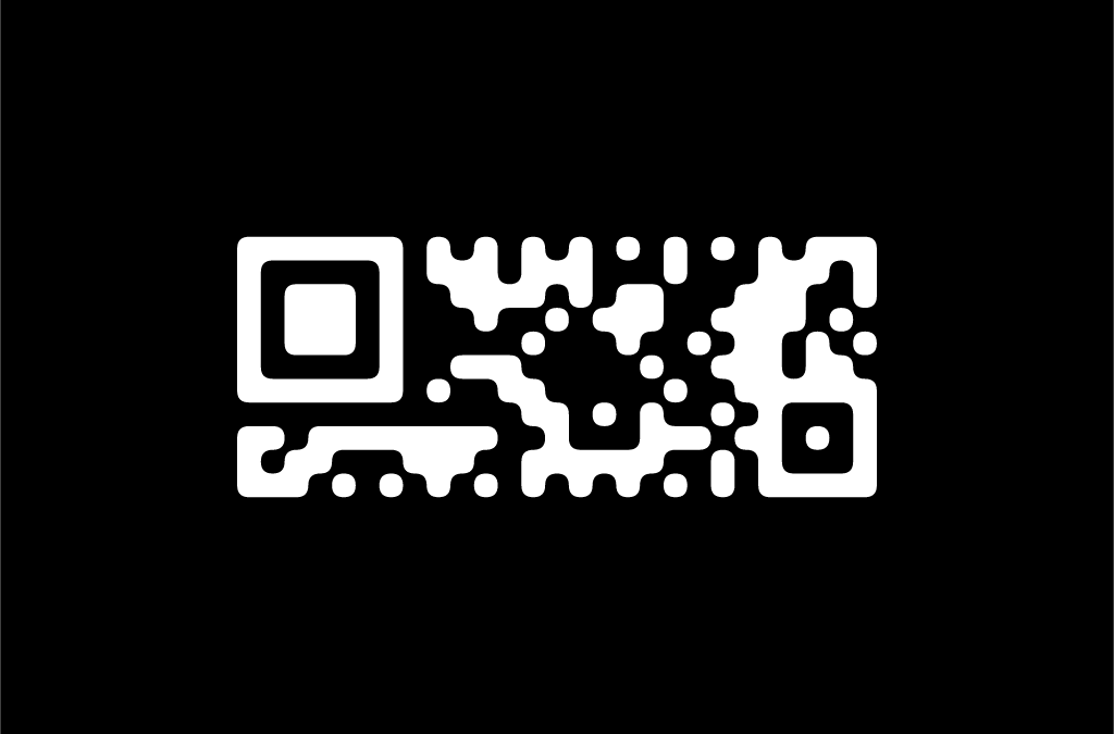
rMQR HACKADAY Few simple and effective available free resources for generating rMQR code generation and decoding.
The following site supports online rMQR, MicroQR, QRcode generation. The source code also available in Github. It is based on RUST implementation
You can try to encode your message into a barcode at HERE
Python based rMQR code generation implementation is available for online generation
You can try it at HERE
This site provides multiple type barcode generation. You can generate rMQR, MicroQR, QRcode, tQR, EAN13, EAN8, UPCA, CODE39, CODE93, NW7 and ITF type of barcodes. This site also provides image decoding or camera decoding.
Qrean wasm demo
Terry Burton's post script based barcode generator supports plenty of barcode types including rMQR code.
You can try the online barcode generator HERE
SMARTPHONE SCANNER:
currently few smartphone apps available for decoding the rMQR. The official Denso site suggest the following app. It is available for both iOS and Android version.
![]()
The android version is available from Google Play
The iOS version is available from the App Store
This App can scan using smartphone camera or photos and images stored in your gallery. This App expects much higher border around the code to decode.
The other App which supports for smartphone is Scandit
The DEMO version available for Android and iOS
The Scandit Demo app supports the rMQR by selecting ANY CODE option on the GUI of the main screen. This app just scans and displays the result and we can copy the scanned message. But the DEMO app doesn't capable of generating the code.
-
MCS-85 Mnemonic
01/26/2026 at 15:17 • 0 commentsMCS-85 Instruction
![]()
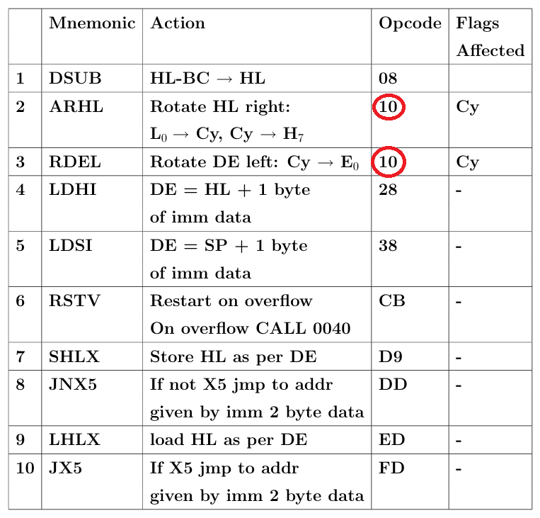
Intel 8085 Mnimonic and opcode
-
COLOR Barcode
01/25/2026 at 15:59 • 0 commentsHigh Capacity Color Barcodes (HCCB) and JAB Code are advanced 2D barcode technologies that use multiple colors to significantly increase data storage density compared to traditional black-and-white codes.
HCCB Technology Developed by Microsoft Research, HCCB uses multicolor symbols and unique shapes to store more data per square inch. Laboratory tests have shown storage of up to 2,000 bytes or 3,500 characters per square inch at 600 dpi — roughly equivalent to two pages of a novel. It supports digital signing using Elliptic Curve Cryptography (ECC) with RSA-1024 equivalent security, enabling data integrity verification. HCCB can store multiple payloads in a small file system format and is optimized for mobile device decoding, even from low-quality images, outperforming QR Codes in some scenarios.
JAB Code JAB Code (Just Another Barcode) is an ISO/IEC 23634:2022 standard for high-capacity color barcodes. It uses colorful square modules arranged in grids, with a primary symbol (containing finder patterns) and optional secondary symbols for scalability. It supports error correction and can encode from small to very large datasets. JAB Code is open-source, with a C-based library for encoding/decoding, and can be built for Linux or Windows.
![]()
JABCODE
jabcode/jabcode: jabcode - color bar code
JAB Code Standard ISO/IEC 23634
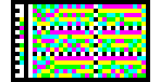
The following sequence of Pi is encoded into JABCODE as follows:
3.14159265358979323846264338327950288419716939937510582097494459230781640628620899862803482534211706798214808651328230664709384460955058223172535940812848111745028410270193852110555964462294895493038196442881097566593344612847564823378678316527120190914564856692346034861045432664821339360726024914127372458700660631558817488152092096282925409171536436789259036001133053054882046652138414695194151160943305727036575959195309218611738193261179310511854807446237996274956735188575272489122793818301194912983367336244065664308602139494639522473719070217986094370277053921717629317675238467481846766940513200056812714526356082778577134275778960917363717872146844090122495343014654958537105079227968925892354201995611212902196086403441815981362977477130996051870721134999999
![]()
Online barcode generator ULTRACODE
Ultracode:
This Symbology is also known as Ultracode 2D Color Barcode a.k.a AIM ISS Ultracode.
The Ultracode symbology is a colour, 2D matrix-style barcode symbology that can encode full 256 character extended-ASCII. It supports six error correction levels.
Example of Ultracode barcode images
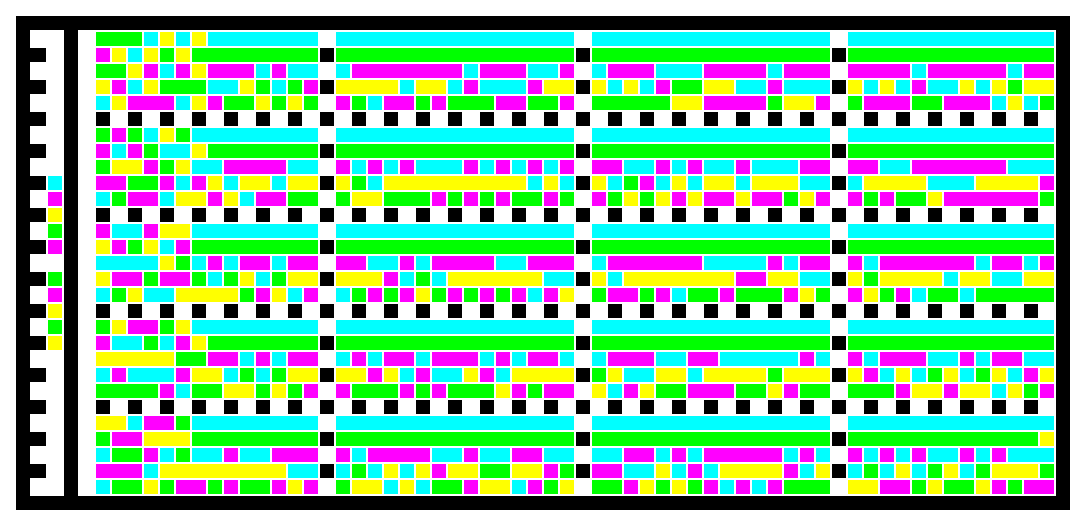
Code property = Lorem ipsum dolor sit amet, consectetur adipiscing elit. will produce the following barcode image:
![]()
Free Online Barcode Generator - Create Print-Ready Barcodes

250 digits of Pi -
tQR
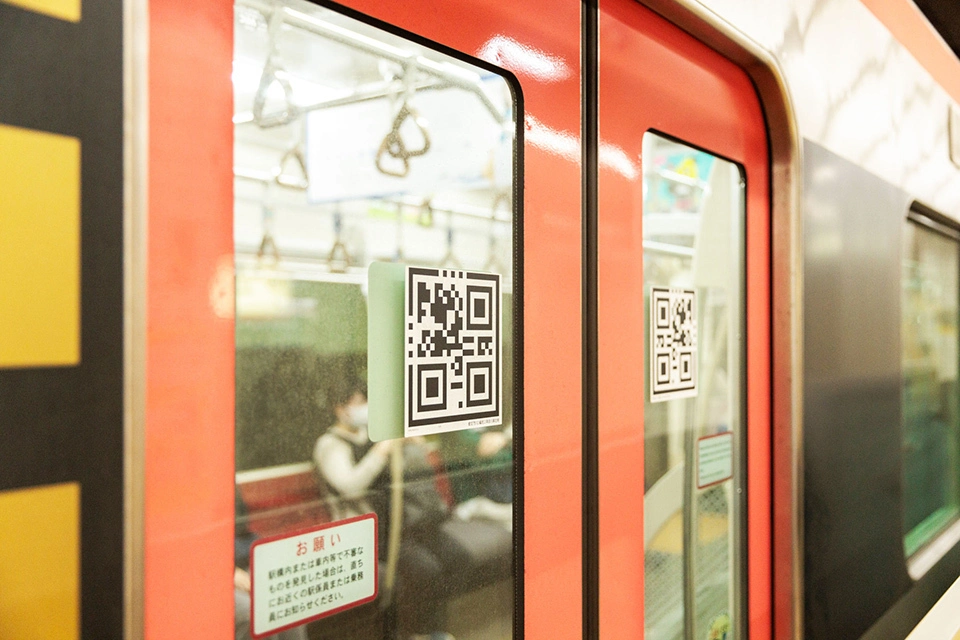
01/25/2026 at 14:16 • 0 commentsToei Subway First Introduces! Automatic Platform Door Control System Based on Denso Wave’s New QR Codes
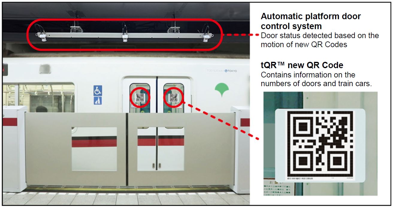
that Toei Subway has adopted an automatic platform door control system based on Denso Wave’s new QR Codes (tQR™) developed jointly with Toei Transportation. The system was first introduced on the Toei Asakusa Line(1). Before this introduction, starting on November 24, 2017, the system was tested and verified on platform doors for approximately one month at Daimon Station. According to Toei Transportation, work on Platform 2 at Shimbashi Station to equip platform doors linked to the system will begin after the last train departs on June 8, 2019. The system is slated to become operational at the station around October 2019.
![]()
According to information released by the Ministry of Land, Infrastructure, Transport and Tourism,(2)to prevent falls from train and subway platforms, a goal has been set to install platform doors at 800 stations around the country by 2020. This system uses QR Codes and platform scanners in place of communication and control devices to be mounted on each train, resulting in lower costs and shorter work times for retrofitting train cars. The system implements the following features:
- Feature 1. Shorter work times for retrofitting train cars Affixing labels printed with tQR Codes to train car doors is all that is required, allowing installation of the control system without major work on the train cars.
- Feature 2. Allows train conductors to open and close platform doors with a single action Platform doors linked to the system can be opened and closed only by operating the train doors, eliminating delays caused by trains forced to stop and wait for platform doors to open and close.
Plans call for the system to be installed by Toei Transportation at Shimbashi, Daimon, Mita, and Sengakuji Stations on Toei Subway’s Asakusa Line ahead of the Tokyo 2020 Olympics and Paralympics. The company is targeting installation at all Asakusa Line stations by 2023.
kikuchan/libqrean: A portable QR and Barcode generation / manipulation library written in C.
![]()
World’s First Platform Doors Using 2D Codes Installed at Toei Subway Stations
2024 marks the 30th anniversary of the 2D code developed by the Japanese firm Denso Wave Inc. The Tokyo Metropolitan Bureau of Transportation (Toei Transportation) has now collaborated with Denso Wave to develop the world’s first 2D-code system for opening and closing platform doors at stations on the Toei Subway Asakusa Line in Tokyo. The two are now offering the technology to other rail operators free of charge.

The special 2D code, or “tQR code,” was developed by Toei Transportation and Denso Wave Inc. Platform doors installed at railway stations prevent passengers from falling on or entering the tracks. Transporting on average about 2.2 million people a day on all four of their Tokyo lines, Toei Subway first introduced platform doors on the Mita Line and quickly saw a sharp decrease in the number of platform accidents. Platform doors were subsequently installed on other lines as well. To operate the doors properly, all train carriages require sensors to allow synchronization of the opening and closing of the train and platform doors. Installing sensors across all trains, however, requires a significant amount of money. On the Asakusa Line, which is run by five different railway operators, including Toei Subway, the prohibitive cost of installation caused difficulties in reaching an agreement on implementation of the doors.
To solve this problem, OKAMOTO Seiji of the Tokyo Metropolitan Bureau of Transportation, who has worked in railways for about 40 years, turned to the two-dimensional QR code, a Denso Wave Inc. registered trademark. “2D codes hold up well against dirt and can carry a lot of data. I thought we could make good use of these codes, so I approached the company and asked if we could work together,” recalls Okamoto....
Read more -
Calendar.BAS
01/18/2026 at 13:14 • 0 commentsMonthly calendar printing program Between 1900 and 2099 using BASIC. Works well with QB64.
10 REM CALENDAR.BAS - LAST EDITTED 31/01/82 20 REM Dr Dobbs Nov 1981 p61 30 REM This program inputs a month and year and 40 REM from that prints the current months calendar. 50 REM 60 DEFINT A-Y 70 DEFSTR Z 80 INPUT "Month";M 90 INPUT "Year";Y 100 IF Y<1900 OR Y > 2099 THEN PRINT "Between 1900 and 2099 please!" : GOTO 80 110 IF M <1 OR M > 12 GOTO 80 120 MONTH = M : YEAR = Y : GOSUB 320 130 DAY = D : YEAR = Y : MONTH = M+1 140 IF MONTH < 13 GOTO 160 ELSE MONTH = 1 150 YEAR = YEAR +1 160 GOSUB 320 170 D=28+D-DAY 180 IF D<28 THEN D = D+7 190 FOR I=1 TO M 200 READ ZMONTH 210 NEXT 220 PRINT " ";ZMONTH; TAB(25); 230 PRINT USING "####";Y 240 PRINT " Sun Mon Tue Wed Thu Fri Sat" 250 PRINT TAB(DAY*4+1); 260 FOR I=1 TO D 270 PRINT USING " ##";I; 280 IF (I+DAY) MOD 7 = 0 AND I < D THEN PRINT 290 NEXT 300 PRINT 310 END 320 REM Compute the day of the week 330 MONTH = MONTH -2 340 IF MONTH > 0 GOTO 360 ELSE MONTH = MONTH + 12 350 YEAR = YEAR - 1 360 CENTURY = YEAR\100 370 YEAR = YEAR MOD 100 380 D= ((13*MONTH - 1)\ 5 + 5 * YEAR\4 + CENTURY\4 - 2 * CENTURY +1) MOD 7 390 RETURN 400 DATA January,February,March,April,May,June,July,August,September 410 DATA October,November,December -
Reading 80C52 Port 3 Bits
03/26/2024 at 16:16 • 0 commentsIntroduction:
While BASIC-52 allows you to access Port 1 bits directly through BASIC, it does not allow direct access of the Port 3 bits available on many of the boards and modules
Background: Port 3 is an 8 bit bi-directional I/O port with internal pullups.
- Port Pin Alternaye Function
- P3.0 RXD (serial input port)
- P3.1 TXD (serial output port)
- P3.2 *INT0 (external interrupt 0)
- P3.3 *INT1 (external interrupt 1)
- P3.4 T0 (timer 0 external input)
- P3.5 T1 (timer 1 external input)
- P3.6 *WR (external Data Memory write strobe)
- P3.7 RD (external Data Memory read strobe)
Program Listing:
Example 1: Waiting for a bit to be set or cleared
BASIC-52 program . . . CALL xxxxh
Assembly routine
xxxxh Label1: JB P3.x, Label1 ;Loop until bit is set RET ;Return to BASIC program
or
xxxxh Label1: JNB P3.x,Label1 ;Loop until bit is cleared RET ;Return to BASIC program
Example 2: Return the state of a bit to BASIC-52
BASIC-52 program . . . CALL xxxxh
Assembly routine
Xxxxh Label1: JB P3.x, B_SET ;Test the bit, jump if set B_CLR: MOV 20h, #0 ;Store 0 if cleared RET
B_SET: MOV 20h, #1 ;Store 1 if set RET
Once you are back in the BASIC program use the following line to read what was stored:
IF DBY(20h)=0 THEN PRINT "P3.x = Low" ELSE PRINT "P3.x = High"
This page is based on Micromint inc's AN101 Dated: 7/28/99
-
Controlling 80C52 Port 1 Bits with Assembly Language Calls
03/26/2024 at 16:10 • 0 commentsIntroduction:
Although the Port 1 bits can be controlled directly through BASIC using the PORT1 command, sometimes its easier to use assembly language calls. This method allows the individual bits to be changed instead of the whole port.
Background:
The following table indicates the addresses for the Port 1 bits:
- P1.0 = 90h P1.4 = 94h P1.1 = 91h P1.5 = 95h
- P1.2 = 92h P1.6 = 96h P1.3 = 93h P1.7 = 97h
If only a few of the bits are being controlled then the easiest way to implement this is by storing the machine code using data statements. The code to set, clear, or toggle a bit takes three bytes of memory (command, address, return).
The machine code commands are used as follows:
NOTE: Assignments must begin with an integer, otherwise the processor will interpret them as a variable.
0D2h = set bit 0C2h = clear bit 0B2h = toggle bit (if set, clear it or if cleared, set it)
Program Listing: The sample program below shows how the commands are stored and then called:
10 DATA 0D2h, 94h, 22h : REM code to set bit 4 of port 1
20 DATA 0C2h, 94h, 22h : REM code to clear bit 4 of port 1
30 DATA 0B2h, 90h, 22h : REM code to toggle bit 0 of port 1
40 FOR ADR = 4000h to 4008h : REM store the codes -this must be a free area of RAM!
50 READ DT
60 XBY(ADR) = DT
70 NEXT ADR
80 REM all commands are now stored in RAM
200 CALL 4000h : REM set bit 3 of port 1
210 CALL 4003h : REM clear bit 3 of port 1
220 CALL 4006h : REM toggle bit 0 of port 1
230 GOTO 200 : REM continuous loop through the three commands
This page is based on Micromint inc's application note AN103 Dated: 5/26/98
-
Weird PS/2 mouse
12/31/2022 at 18:07 • 1 commentWhat is PS/2?
The PS/2 (Personal System/2) port, also referred to as the mouse port or keyboard port, was developed by IBM. It is used to connect a computer mouse or keyboard to an IBM compatible computer. The PS/2 port is a mini DIN plug containing six pins and is still sometimes found on all IBM compatible computers.
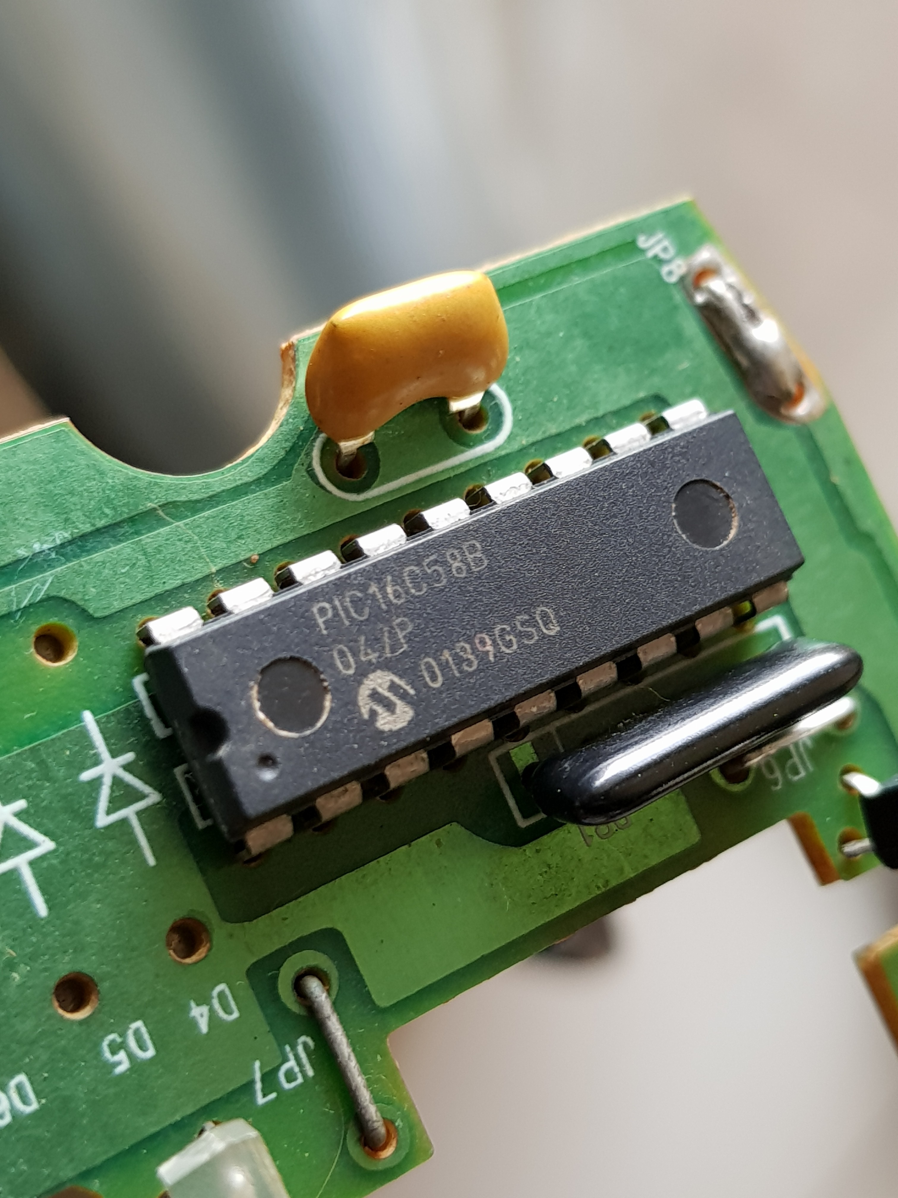
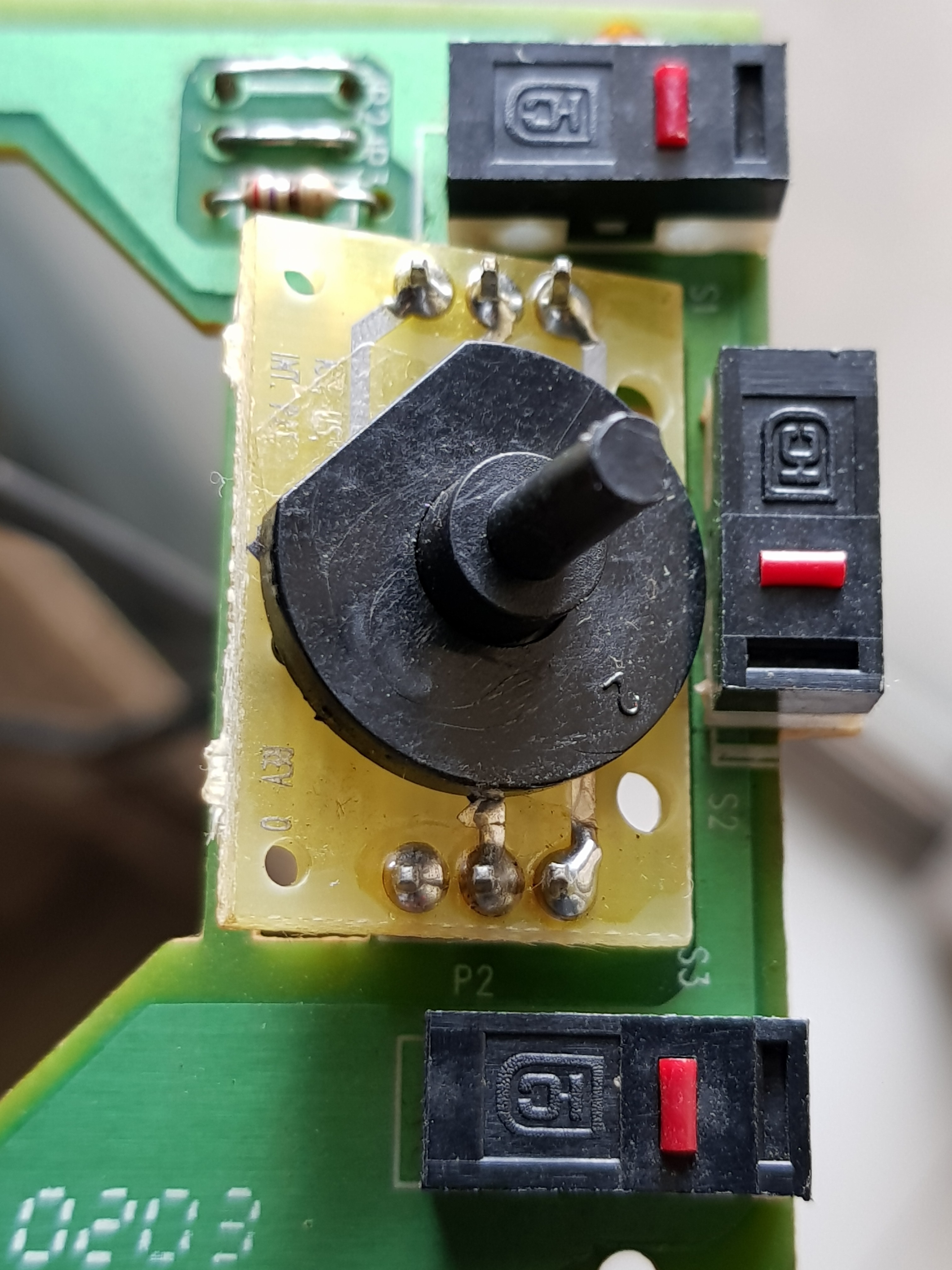
Came across a PS/2 mouse.
![]()
The mouse controller is PIC16C58!
![]()
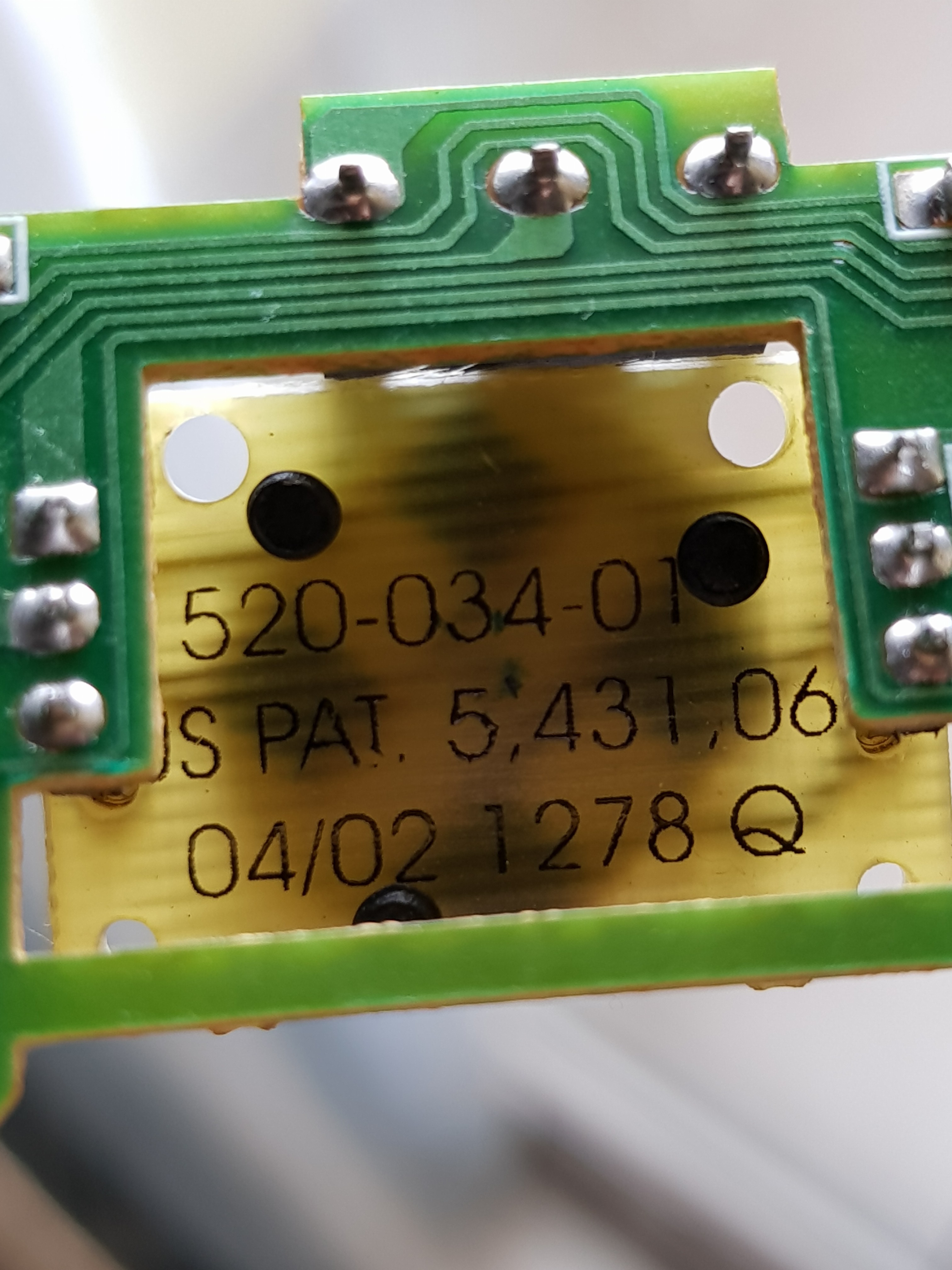
Touch or pressure sensor covered by US5431064A patent
A pressure sensitive transducer array in which a plurality of transducers are connected in series and in parallel with one another. In one embodiment, a resistive layer is formed from carbon or silver ink on a polyester film. A plurality of conductive shunt elements having greater conductivity than the resistive layer is formed on a second polyester film. The films are placed adjacent to one another with the shunt elements contacting the resistive layer. Voltage is applied across the resistive layer and pressure is applied thereto. As the pressure increases, the number of current paths set up through contact points on the shunt elements increase thereby decreasing the resistance across the resistive layer and increasing current flow. In another embodiment a plurality of plate elements are contained in a plane on one side of a dielectric layer. A plurality of plate elements are contained in a plane on the other side of the dielectric layer. As the layer is pushed together responsive to force applied, total capacitance as measured across the planes of plate elements varies.
![]()
Sensor bottom view
-
UPC barcode generator
12/23/2022 at 11:00 • 0 comments000 REM UPC/EAN CODE GENERATOR 010 DIM p$(29), c%(12), q$(9), m%(100) 020 INPUT " Enter the Number : "; u$ 030 FOR i% = 0 TO 9 040 READ n$, s$ 050 n% = ASC(n$) 060 s% = ASC(s$) XOR &H3F 070 WHILE n% <> 0 080 p$(i%) = RIGHT$(STR$(n% MOD 2), 1) + p$(i%) 090 p$(i% + 10) = RIGHT$(STR$(n% MOD 2 XOR 1), 1) + p$(i% + 10) 100 p$(i% + 20) = p$(i% + 20) + LEFT$(p$(i%), 1) 110 q$(i%) = RIGHT$(STR$(s% MOD 2 + 1), 1) + q$(i%) 120 n% = n% \ 2 130 s% = s% \ 2 140 WEND 150 NEXT i% 160 FOR i% = 0 TO 11 170 c%(i%) = VAL(MID$(u$, i% + 1, 1)) 180 X% = X% + c%(i%) * (((i% + 1) MOD 2) + (3 * (i% MOD 2))) 190 NEXT i% 200 c%(i%) = (10 - X% MOD 10) MOD 10 210 FOR i% = 1 TO 6 220 l$ = l$ + p$(VAL(MID$(q$(c%(0)), i% + 1, 1)) * 10 + c%(i%)) 230 r$ = r$ + p$(c%(i% + 6)) 240 NEXT i% 250 f$ = "606" + l$ + "06060" + r$ + "606" 260 KEY OFF: SCREEN 2 270 PRINT LEFT$(u$, 12) + RIGHT$(STR$(c%(12)), 1) 280 GET (0, 0)-(13 * 8, 8), m% 290 SCREEN 11: CLS 300 REM PAINT (0, 0) 310 PUT (15, 35), m% 320 FOR i% = 1 TO 95 330 b% = VAL(MID$(f$, i%, 1)) 340 LINE (20 + i%, 5)-(20 + i%, 25 + b%), SGN(b%) XOR 0 350 NEXT i% 360 WHILE INKEY$ = "" 370 WEND 380 KEY ON: SCREEN 0 390 END 400 DATA r,?,f,4,l,2,B,1,\,",",N,&,P,#,D,*,H,),t,% Confirmed working under QB64 on Windows 11 Pro.![]()