-
Floppy shenanigans
11/13/2017 at 20:07 • 6 commentsbeen learning a lot about floppy drives/disks/controllers lately, what with #Floppy "Fun" -- Backing up a unique Kay-Pro disk and #Improbable AVR -> 8088 substitution for PC/XT
Also finally started attacking a long-planned project to record audio directly onto floppy disks...
So, here I plan to throw random unexpected discoveries that may be useful for floppy endeavors of all sorts.
(Many Many more are buried in logs at the projects linked above).
1) the /STEP input is *not* directly fed to the stepper motor driver. Boolean logic determines whether the drive pays attention to the /STEP input. Primarily: the drive *will not step* if /WG is active.
(This Teac drive manual actually shows the logic equation... and similar equations exist and are explained for other I/Os as well...)
2) if /WG is active when the index pulse arrives, the pulse is extended (dramatically) presumably to indicate to the host controller that the write process was truncated (?).
I vaguely recall reading about this extended pulse somewhere (and plausibly whether the write actually gets truncated, or whether it's allowed to overwrite the beginning of the track) but have yet to relocate that source.
3) microstepping?! Fiddling with /WG and /STEP timings, I noticed it may actually be plausible to acheive some level of microstepping. More logically, /STEP and /DIR could plausibly acheive this as well. Precision more likely than accuracy, so maybe not so useful when using disks for storage, but maybe something to fiddle with. (One thought... maybe possible to use Step/Dir microstepping in attempt to read tracks written on a poorly calibrated drive... or, e.g. where a 5.25in disk has an oblong hole, from years of wear).
The odd thing about /WG's effect on stepping... I was under the impression that /STEP must be (falling)edge-triggered... the outputs of the motor driver holding their new state after the edge. But then /WG's only effect should be that of either allowing or blocking the transition to the next state. Then there should be no fractional (or incomplete) steps. But almost certainly I could hear attempted steps cut short.
That would imply...
4) /STEP is not edge-triggered (?!)
And, actually, that makes some amount of sense based on my readings which I didn't quite wrap my head around until just now... combined with knowledge of the stepper motor driver chips used in some (macintosh) drives I've scrounged for their... wait for it... stepper-driver chips. These chips have two supply voltages for the motors... 12V for seeking and 5V for holding.
![]()
![]()
And the readings...? As I recall, the stepping-procedure for drives allots various (adjustable) time parameters for head movement... step-rates made sense to me; don't try to step too fast or the head won't overcome static friction, and steps will be missed. Head settling time; after a step, the motor will bounce briefly before settling into its new position... give it a certain amount of time to settle. But there were other step-timing parameters I didn't grasp... and I'm betting one of them is the duration of the /STEP pulse, which probably also determines the duration that the new state is supplied with 12V to nudge that motor into that new position... (note the drive I'm working with now only has a 5V supply, but may use a similar seek/hold scheme).
Aside: I used those motor drivers (once removed from the drives) for quite a bit of experimenting... #CD/DVD mechanisms and cartesian thinggie[s?] microstepping was definitely doable, but also causes quite a bit of heat... also, I worked with the driver chips themselves, which had separate...
Read more -
Ode to My Oscilloscope...
11/07/2017 at 14:20 • 3 commentsI love my oscilloscope almost as much as one can love a machine...
My oscilloscope is *both* analog *and* digital.
This ain't no small potatoes...
We're talking: Its "bandwidth" is 20MHz, but I've diagnosed signals up to 128MHz, by adjusting various scaling-factors, in analog-mode.
In digital mode... well, it's pretty limited. 20MS/s means Nyquist would say we can't view anything greater than 10MHz, and then, only *barely*. Allegedly it can view repetitive signals at much higher sample-rates in "EQUIV" mode, which I assume does-so by *beginning* sampling at different delays after the trigger... I've had... sporadic luck with this.
But... at signal-rates lower than 10MHz, the digital-mode it does quite nicely... E.G. being able to "scroll" low-frequency signals is *awesome*... and, as far as I'm aware, completely impossible via analog-only means. Similarly, the ability to "hold" and then, essentially, "dump" a screenshot... well that's quite handy. It also does averaging and various interpolation-methods, but not things like... what I'mma call "windowing" wherein it'd show both the min and max values sampled at each sample-point (limited sample-memory, only seems to handle about one screen).
Now, in this era a 20MS/s 'scope ain't hard to come by... (nevermind RAM)... And, if I understand correctly, most digital 'scopes today that claim e.g. 20MHz sample at 10x that (200MS/s). So, by-far way better than this guy... (Though, there is a bit of debate as to whether cheapo-'scopes that claim such rates actually have the analog-front-ends to support it).
Anyways, I *have* actually diagnosed 128Mb/s signals, of certain forms, on my allegedly 20MHz analog 'scope... aliasing isn't a factor in the analog realm... It Can Be Done... And, so, analog is quite a nice thing at times...
(E.G. say your "20MHz" digital-only 'scope samples at 200MS/s... Nyquist says that you'll never see anything greater than 100MHz on that screen, without its being severely distorted by aliasing... Though, again, there may be ways 'round this, e.g. when you know a signal is repetitive, and your triggering is highly-accurate, and your software-programmer and circuit designer were "extremely" on the side of "clever").
.....
Anyways... It's been a long-running idea to replace the digital circuitry in my 'scope with something a little more capable in today's technology...
I've yet to come across a service-manual (as opposed to user-manual) for this guy, so I guess we'll have to start with some reverse-engineering...
.........
Oh, BTW, this is a Goldstar OS-3020, which appears to also have been labelled as LG (Lucky Goldstar?) OS-3020, also plausibly EZ-Digital OS-3020, It's of the OS-3000 series (which comes in 20, 40, and 60MHz varieties, along with the OS-3040, OS-3060... And I've seen e.g. OS-3020D, OS-3040D, and OS-3060D part-numbers, as well...
The user-manual shows BASIC listings for how to work with it... I mean, Cool. No?
......
Anyways, lacking schematics, here's some stuff for posterity:
The digital-board is located under the CRT... I guess the CRT's sheilding makes that possible.
The "big" components on the digital-board are:
U2412 HD64180RCP 10X (CPU, 10MHz, ZILOG Z180/Z80180 "fully-compatible", 1MB address-space... kinda funny I've been doing so much with Z80's recently. @Ziggurat29, any interest in disassembling this thing?).
U2402 XILINX XC2018-70 (Gate-Array... ??? Video-controller ???)
U2422 EPROM: TMS27C512-15 (Boot-ROM, 64KB)
.....
Also:
82C55 - (2x) Programmable Peripheral Interface
82C54 - (2x) Programmable Interval Timer
HM63021 - (2x) 2KByte "serial-access" SRAM
[H]A19211B - (2x) 20MS/s 8-bit A-D converters
... Read more -
Contemplations on CMOS/TTL interfacing/hacks
01/05/2017 at 09:56 • 0 commentsDiscussion with @Ted Yapo and @jaromir.sukuba over at one of my project's logs wound 'round to the concept of level-shifting for various CMOS voltage-supplies and TTL... and it got me thinking.
The basic gist of that conversation was:
3.3V CMOS outputs can typically drive TTL inputs, but cannot be relied on to drive 5V CMOS inputs. Similarly, it's not reliable to feed a 5V TTL output into a 5V CMOS input.
Thus, there's the 74xCT series (ACT, HCT, etc.).
Basically, if you want to interface a TTL output signal to a 5V CMOS input, you should use the HCT or ACT series, rather than the HC or AC series, at that juncture in the circuit.
And, as I understand, that same series can be used to interface a 3.3V CMOS output to a 5V CMOS input.
There should be plenty of info about this 'round the web, and surely more reliably-documented than anything I could come up with. Look for "level-shifting" and check out the datasheets for these series.
------------
This "page" is mostly about hacks. These concepts should *NOT* be used in products, without *carefully* looking into the details that I won't be going into, here, to any extent except to throw out some ideas/experiences... for HACKS-SAKE.
-----
So, here are some of my experiences with the TTL series' running at 3.6V. We're talking e.g. the 7400, 74S00, 74LS00, and 74F00. They're only spec'd down to 4.5V, but I have had some luck using TTL at 3.6V, and you might too.
- For #sdramThing4.5 "Logic Analyzer", as regular-ol' glue-logic, a MUX, a latch, and some boolean-logic. There were definite performance-hits, but it was functional. I eventually "upgraded" to the HC series and, of course, the system was able to run faster. But. "It worked" with lowered-expectations, and a lot of experimentation, 'scoping, etc. with TTL's running at 3.6V.
- For that system, as well as my AVR-based LVDS-LCD controller: https://sites.google.com/site/geekattempts/home-1/drive-an-old-laptop-display-from-an-avr I've used 74LS86's (alternatively 74LS00's, and 74LS32's) running at 3.6V to drive the LVDS signals into old laptop displays. (much slower than normal FPD-Link... 16-128Mbps). Note that LVDS has a differential voltage of something like 0.1-0.3V, and has a 100ohm load at the end, which just happened to work out darn-near perfectly when directly-driven by the LS86's. Again, a lot of experimentation went into this! But the key, here, is that "it worked" *way* out of specs, and surprisingly reliably (two systems running 24/7 for over a year!).
Again, Neither of these experiences should be *expected* to work for you just because I happened to luck-out. But, for hack's sake don't be deterred from giving it a try (and expect it to be flakey!).
---------
Why? Mostly because those were the supplies I had on-hand.
Actually, the LS->LVDS system went through *many* iterations involving better-suited systems before settling on the (simplest) direct-driving via 74LS86. Another attempt used AHC parts, an inverter and a buffer. These are CMOS, rated for 3.3V, quite a bit faster, and most importantly (for LVDS) have much higher drive-strength, thus requiring series-resistors to keep the voltage low-enough.
--------
The recent discussion with Jaromir, as I said, got me thinking a bit about the xC vs xCT series. As I understand, the xCT series is basically identical to the xC series *except* that its inputs are rated for TTL-signals.
So... does that mean that the internal circuitry is identical, exclusive of the inputs?
The thing is: I've access to a bunch of ACT parts, but not so many AC. Similarly for HCT and HC. Others might run into the same when working on a project at a hacker-space, hackathon, convention, etc.
So, why the question...? Because ACT and HCT are *only* specified for 4.5-5.5V, just like TTL. But, if internally they're identical to the AC and HC series, then maybe they *can* run at the AC/HC power-supply-voltage-levels somewhat happily... (Maybe even with very similar timing-specs to the AC/HC...
Read more -
40107 Ch2 - The Saga Continues
12/04/2016 at 19:26 • 0 commentsSee Chapter 1 over at: https://hackaday.io/page/2303-40107
-----------
When I first signed up for this account I was like "oh yeah! I'm a pretty cool part-number!" And then I realized the part-number I thought I was was actually the 40106.
The other day I stumbled upon another 40107:
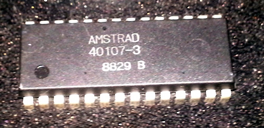
This guy was sitting in my "unsorted ICs" bin, which mostly came from old motherboards, etc.
(I was sorting through it trying to find cool uCs/CPUs to use for the 1k Challenge).
But, this guy... This guy... Oh man, I remember this guy!
How cool is it that it has my user-number?!
'Cause, when I was 15, I built an LCD controller... The biggest TTL project I'd ever attempted, and amongst my first microcontroller projects:

https://sites.google.com/site/geekattempts/old-projects
And a HUGE part of designing that circuit was reverse-engineering that friggin' LCD display... for which there was basically no data, and despite having somewhat standard row/col drivers (whose datasheets took *weeks* to locate in the early-internet-era), those were driven by an unknown programmable-logic device.
So, some guy was awesome enough to respond to a forum-post with a schematic of the motherboard this was originally connected to (where he got it? Boggles my mind):
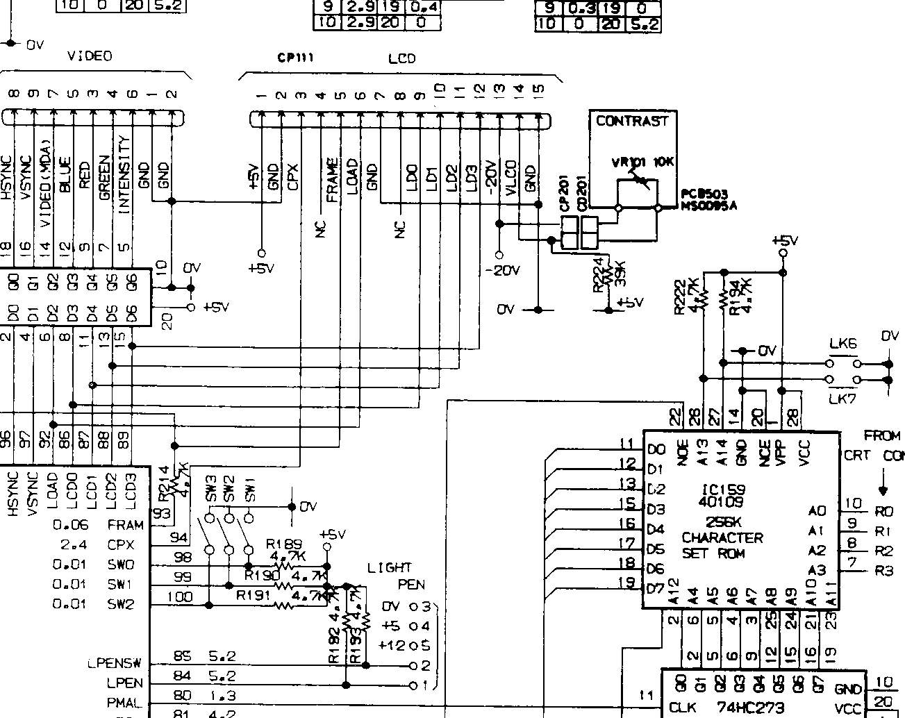
From this I was able to figure out the missing pieces regarding what to feed that PLD, and obviously, the much-needed pinout (nevermind contrast, -20V, etc.).
So, obviously, this image is somewhat-deeply ingrained in my brain... And stumbling upon that 40107 chip marked "AMSTRAD", this image popped into my head... and I was like "Whoa, this is the character-set ROM for my LCD project!"
.... yeah... no. That's the 40109.
But it was a pretty cool moment, anyhow. And pretty funny, looking back on it. And even funnier when you consider I did similar with the 40106 CMOS chip.
------------
So I did some searching, and it turns out the 40107 is a BIOS ROM, I think, from that same machine... One of two (for the 16-bit bus?).
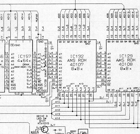
And a little bit more searching resulted in a page where someone had listed all the ROM chips used in Amstrad computers, and another page where these ROMs are actually referenced in the source-code in a project on Github... Weird? (Emulator?)
It's pretty wild how much info is out there...
------------
The machine these came from... that's another story, but let's just say the Amstrad PPC640 was a pretty groovy "portable" (read: luggable all-in-one) PC-compatible that I used to carry around with me, coding in Basic, and playing old games, even during the early Pentium era:

And I feel a bit ridiculous for having taken *two* of them apart (who gave me these, anyhow?! And did I really have *two* at one point?! I definitely have two *screens*. Weird.)
...
Ahhh the ridiculous rabbit-holes...
Anyways, I suppose I might try to think of something to do with that 40107 to go along with my other 40107's (I think I ordered two)... So now I've got a ROM and some NANDs... 'spose I *could* use that ROM's randomish-data as something like a "character-generator" or "sprites"... or...?
-
Smart Cat
10/13/2016 at 12:27 • 2 commentsOne would have to be a fool not to acknowledge the symmetry of this...

Is it a dog...? She had a run-in with the neighbor-dog today... the first interaction they've really had... He's got a really short/stubby tail, and really short legs...
Also, I make "soup" for her by pouring some of her water into the kibble... Numerous times I've found her water dish tipped over toward the kibble-dish. Recently I found kibble-remains sitting at the bottom of the water-dish.
I feel an inexplicable urge to carve her likeness out of stone.

Or maybe the 16x16 display I've got running on an AVR, the one with the resistive-touch-screen would give her more artistic outlets...
 https://sites.google.com/site/geekattempts/home-1/drive-an-old-laptop-display-from-an-avr
 -
40107
09/23/2016 at 07:41 • 4 commentsWhen I first signed up for this account I was like "oh yeah! I'm a pretty cool part-number!" And then I realized the part-number I thought I was was actually the 40106. ( @davedarko, I distinctly recall your calling me out on this one ;)
Today I stumbled upon the 40107:
http://www.goldmine-elec-products.com/prodinfo.asp?number=A10184
 There it is. My user-number, on a 14-pin DIP, just as I imagined...
Interestingly, the only thing the page says about it is:
CD40107BF in 14 pin DIP. Manufactured by RCA.
Which, of course, is all clear-as-day just by looking at the picture.
So, then, search for CD40107BF, CD40107, CD40107B...
http://www.ti.com/product/CD40107B
NAND... well, that's pretty durn cool, really... Maybe cooler than a lowly ol' inverter, even a Schmitt-triggered inverter.
Actually, it's danged-cool, 'cause yahknow, *every* gate can be made of combinations of NANDs. Awesome! Put enough effort into it, and you could build an entire computer outta no other IC's than those with my user-number on 'em. Perty Snazzy.
And Open-Drain, no less, up to 136mA at 10V, or could handle a load as high as 20V... meaning yahknow, you can use my part-number to do things like directly drive relays or incandescent bulbs...
*as well as* do *all* logical-computations... Using no other semiconductors than those with my user-number, you could build not only an entire computer, but also interface it with the real-world, not even needing to add transistors inbetween your 40107-based CPU and your relays or lightbulbs... Slick!
YEAH! SO VERSATILE!
------
But wait, what's this...?
DUAL 2-input NAND...
DIP-8...
WTF?
I'm looking at a picture of it, DIP-14!
-------
TODO: Read more in this interesting-looking page, http://homepages.nildram.co.uk/~wylie/ICs/monolith.htm which states (regarding 3-digit date-codes):
However, there are cases where the decade is 1970, such as the RCA 4000 series CMOS chips
So, judging by the image, above, this guy was most-likely (or, maybe, allegedly?) manufactured in the first week of 1970.
Also interestingly, that same page (and its link) states that RCA, itself, introduced CMOS via the CD4000-series:
The arrival of the RCA CD4000 series of CMOS chips, originally known as COS/MOS, is particularly well-covered by Wikipedia. This was the last major IC technology to be developed, and is still used for all ultra-scale circuits such as microprocessors.
ooooh, let's continue down this ridonculous fractal-branch (or, apparently as most normal-people would refer to such things, this "rabbit hole") because, frankly, I've gone down far too many rabbit-holes that wound-up being downright horrendous, it's time for a good laugh, even if it's at my own expense for wasting so much time following this fractal-branch.
Was planning to order ten, just for the sake of having some stock... but now that I see this thing is apparently non-existant, maybe I should order a few more, in order to have some fryables while trying to determine what this thing *really* is...
So, that linked wikipedia article says:
The 4000 series was introduced by RCA as CD4000 COS/MOS series in 1968
So I don't quite grasp why they date-coded their chips with a year-marking starting with 1970, but that's another branch of this fractal I haven't quite the energy to look into.
Anyways, here's this chip, 14-pins, marked CD40107BF, which is a standard-ish marking for a 4000-series chip from RCA... And, maybe, bought by Harris, which was apparently later bought by TI... (which is the only datasheet I can find)
.............................
OIC.
Oh. I. See.
Several pages down...
Well, anyways...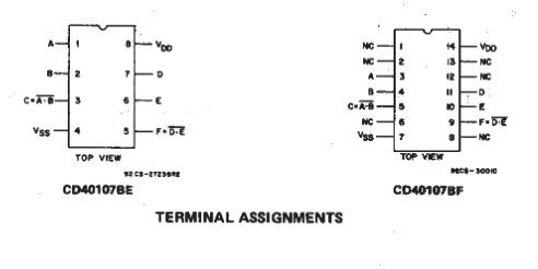
Somehow it all makes some amount of sense...
They *coulda* thrown 4 2-input NANDs in a 14-pin package... but they apparently opted not to. It's rare to see a chip with so many NC's. Maybe it has to do with power-dissipation. So... it'd take a heck-of-a-lot of these guys to build that CPU... And, don't forget all the pull-up resistors. It'd be SLOW. But doable. And it'd take nearly twice the space, using these 14pin DIPs,...
Read more -
Repurposing IDE-Cables (even for video!)
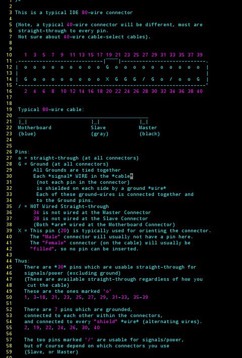
10/25/2015 at 07:45 • 10 commentsBriefly: 80-wire IDE cables are *great* for high-speed stuff... But the pinout is a bit more difficult than a straight-through 40-wire IDE cable, because the 80-wire cables have shielding (yay!) which is connected to specific pins designated as ground, as well as cable-select for master/slave.
This "document" shows which pins are available for your own use, and some suggestions as to how to make use of 'em.
---------------
80-wire IDE cables are quite useful, and are quite easy to acquire...
Cut off one end, and have a nice little jumper for between-boards on your own custom circuits. Strip the ends of the wires on that remaining cable and have a great "breakout" for a shit-ton of signals.
They have shielding between each signal wire. Cool. And that shielding is inherent to the cable itself, so there's no need to connect a whole bunch of pins to ground. Awesome.
BUT: That "automatic" shielding comes at a small price... You can't just use *any* of the pins in your cable for a signal. Below is a listing of the usable pins for your projects...
DEFINITELY SEE ALSO lower down the page, pinouts that are vertical... Why didn't I think of that? Thanks @Hacker404 . But, forgive me, I'm gonna be kinda partial to these for a little while, since I drew 'em.)
NOTE: The information below was determined by probing pins on a few cables. I have since run into cables wired differently (e.g. a master-only cable used insude a USB->IDE drive bay). Further, reading the specs at Wikipedia suggest a different standard-pinout than below! (e.g. pin34 at the mobo side is allegedly grounded, while the Master and Slave pin34s are connected together, ungrounded). Scroll to the bottom for the IDE pinout as compiled from several sources).
I think the main takeaway is just don't plan on using pins 20, 28, and 34. And maybe best to remove/clip those at the header, lest plausibly short something to ground, through the cable, unexpectedly.
![]()
Uses:
I have used this connector/cable combination for sending parallel video data between two boards over several inches. (e.g. between the "Master" and "Slave" connectors on the cable, the "Motherboard" connector and cable removed with scissors).
I also used a few inches of this cabling for the monitor I originally wrote this on, which used FPD-Link/LVDS. (Wire-pairs in LVDS are typically twisted together, but it seems to work fine in this setup with each signal-wire separated by a shield, as in the 80-wire IDE cable.) That display was 1600x1024 at 60Hz... way more than 33MHz pixel-clock.
I've, personally, settled on a couple "pinouts" that I've used in several places: one for parallel and one for FPD-Link video-data. It makes it quite easy to slap-together various converters... One board has DVI->Parallel, another Parallel->Dual-Pixel-FPD-Link. Another is used in the monitor I'm staring at: between the LVDS output on my VGA->LVDS converter (ebayed) and the unusual LVDS connector used by my monitor.
Also, I've recently found a pinout/orientation that works well with a Raspberry Pi's GPIO header for 18-bit color via DPI. [See below]
Of course, there's no reason to limit this connector to video signals (heck, it was used for hard-drives originally), but video's probably a pretty good stress-test of how clean these signals are... what data-rates we can expect to be reliable...
![]()
![]()
Expectables:
The latest-and-greatest of these cables are used with UDMA-133 (as I recall). That's 133MB/s, and I believe that's a guaranteed speed, which likely takes into account the lowest-quality cables they expect from manufacturers (and might even include older 80-wire cables from e.g. the UDMA-66 days?).
Thanks to @Yann Guidon / YGDES for correcting me on some logic... I think the best *guaranteed* signal on a UDMA-133 cable, then, is 33MHz.
That's down an entire 18inch cable, with two connectors, two loads, and surrounded by tons of really noisy power cables and other circuitry.
... Read more -
Project Ideas
06/15/2015 at 14:32 • 4 commentsI lost all the images here! Links and uploads!
:(
slowly rebuilding...
Project Ideas... In order of most-recently-listed, first (read from the bottom-up):
12-5-18: YES!
10-24-18:
https://hackaday.com/2018/10/24/av-synth-is-psychedelic-analog-mayhem/
This is kinda where I saw some old ex;periments with LVDS displays going. A shift-reg for the "blue" channel, would position hsync, vsync, and DE, another for the Pixel-Clock, but the rest of the signals ("red" and "green") could be analog... A lot of these displays can handle weird-timings, with equally-weird effects.
CRANKY CHARGER (10-31-17)
(Update 12-12-17: I think the/a flaw with this/my approach has to do with there being no way to *force* the charge to flow from the cell into the battery... with a switched-inductor the charge *has* to flow somewhere... but as an extreme example, an open-circuit cell or capacitor is just as happy holding its charge.)
(Update 12-9-17: @Ted Yapo thinks a car can be started with a coin cell! https://hackaday.com/2017/12/08/coin-cell-challenge-jump-starting-a-car/ )
(Update: 11-20ish-17: I have run simulations... and no luck. Can't wrap my head 'round it... something about capacitors storing *charge* rather than voltage? The 'battery' never charges past its initial value. Huh.)
So... you've got a (small) 12V lead acid battery and a whole bunch of nearly-dead 1.5V batteries, or maybe a single .6V solar cell... and wish to charge that 12V battery...
Imagine that solar cell, or that 1.5V battery as a cup of water, and that 12V battery as a bucket... somehow you've got to raise that cup up over the edge of that bucket, then pour.
So... take a bigass capacitor, tie it across your 11.7V (slightly drained) battery... once the capacitor is charged, disconnect the positive terminal, throw the solar cell or AA in series, and connect its positive terminal to the soon to be 11.71V battery. Repeat. Repeat. Repeat.... no?
Obviously this could be automated and improved... but I'm visualizing it a bit like a crank on a water well, so could just as easily be done with a rotary switch.
I wonder if that tiny solar cell from my old calculator could eventually charge this 1.5AH 12V battery with nary an inductor. Or whether I could "theive" those last joules from my AAA's this way.
@davedarko had a series/parallel switched capacitor-bank a while back... and @starhawk recently reminded me that really-dead 9V batteries are still usable with 4000-series CMOS chips (Unlike four minorly-depleted AAAs running TTL chips, blah!) Bringing back the thoughts of ultimate battery depletion (recycling!).
Oh, of course, the bigass cap will eventually need to be put in parallel with the 12V battery before use...
...And... fsck... not only has the bold button (and others) disappeared, but so have all the pictures, ?!
[SMARTER] IDE Drive-replacement
11-24-18: This has gotten too long! So I've created a project page. It's still very much in the "idea" stage, though.
https://hackaday.io/project/162439
------
#Let it Snow, starfields, what else...? Maybe a sprite, maybe not... 1k? (12-8-16)
----
Processor-Replacement Revisited (see below) (12-8-16) (UPDATE 2-5-17)
Been looking into 8086's recently, half-tempted to put together an old PC/AT/Compatible for some learning/"hacking" (maybe even develop a system ground-up, but that's unrelated to this).
Occurs to me: 8086's ran at rates from 5MHz - 10MHz... BUT the instructions require multiple-clock-cycles to execute. According...
Read more -
Random Fun Things In My Collection
04/27/2015 at 15:18 • 3 commentsHitachi HD68P01V07:
Just Look at it!
 Seriously, it's got a socket for an EEPROM built-in!
HOLY CRUD: It has *dual-procesor* support!
http://pdf1.alldatasheet.com/datasheet-pdf/view/122457/HITACHI/HD68P01V07-1.html
----------
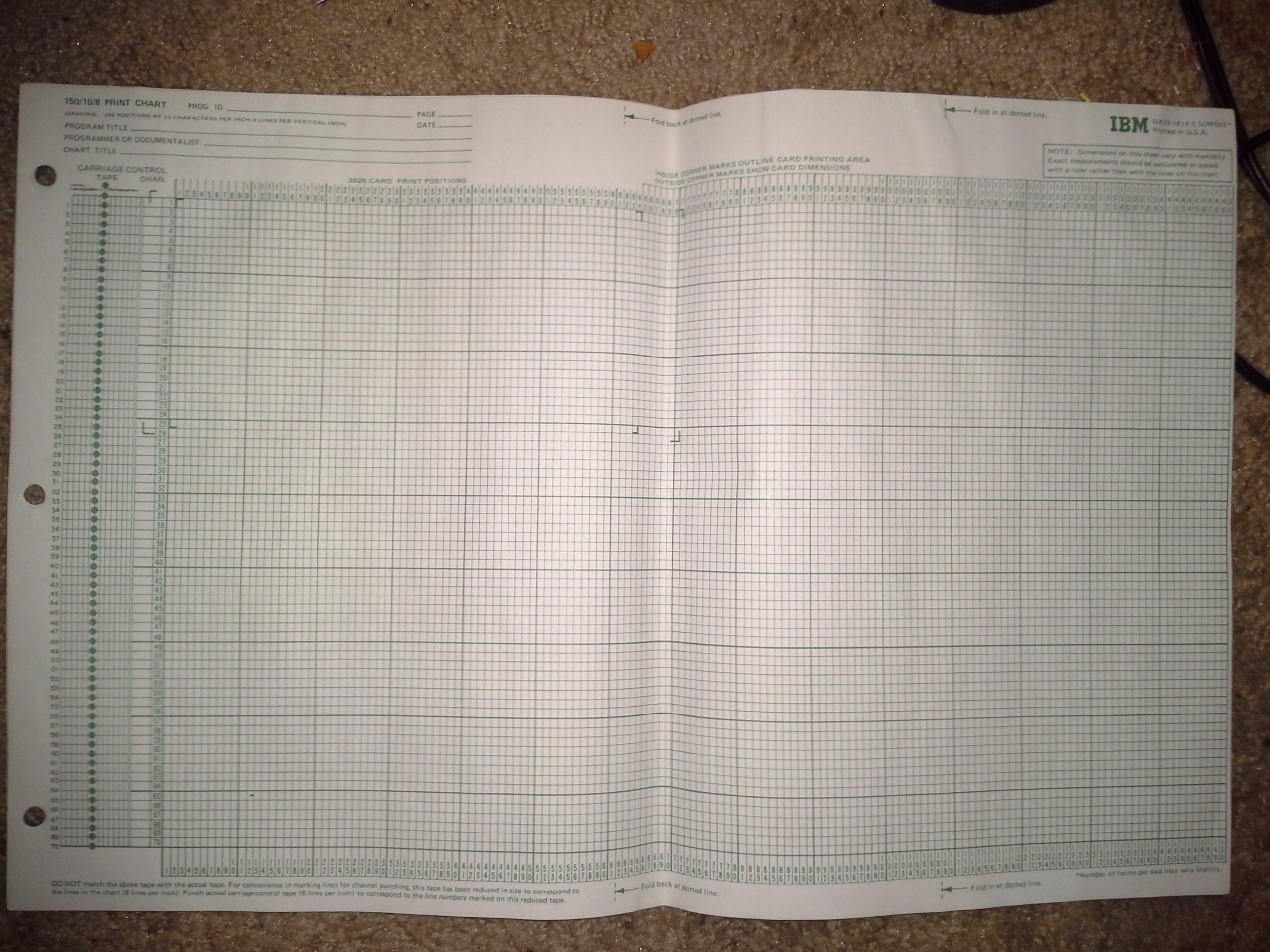
This paper appears to be for punch-cards. My buddy and I were planning to play a long-distance long-term game of "Battle Ship" with it. I should probably stop using it as graph-paper... It's probably pretty rare these days!
IBM GX20-1818-1 U/MO25
"NOTE: Dimensions on this sheet vary with humidity."