-
DIY breadboard push button
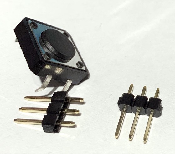
04/26/2019 at 20:50 • 0 commentsMost buttons can't be used with a breadboard because the pins are too short. For example these nice button I bought for $0.12 each. But you need only some pin headers to fix this:
![]()
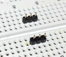
First plug in the pin headers in a breadboard:
![]()
Then clip the button on the pin headers. You might need to bend the pins of the button a bit so that it is a tight fit and the pins of the button are at the outer side of the pin headers on each side, so that it doesn't fall off when you solder it:
![]()
Then solder it, done:
![]()
You can buy a professional PCB for it now in my Tindie shop as well:
https://www.tindie.com/products/frankbuss/breadboard-push-button/
-
Programming an iCE40HX4K with an Arduino and Python
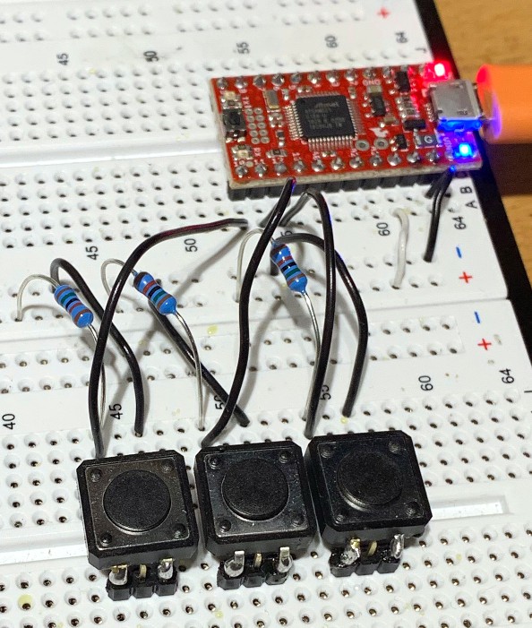
04/19/2019 at 13:05 • 0 commentsYou can program an iCE40 FPGA with a microcontroller, for example an Arduino with 3.3V IO. I tested it with a SparkFun SAMD21 Mini Breakout and a custom board. This is the setup:
![]()
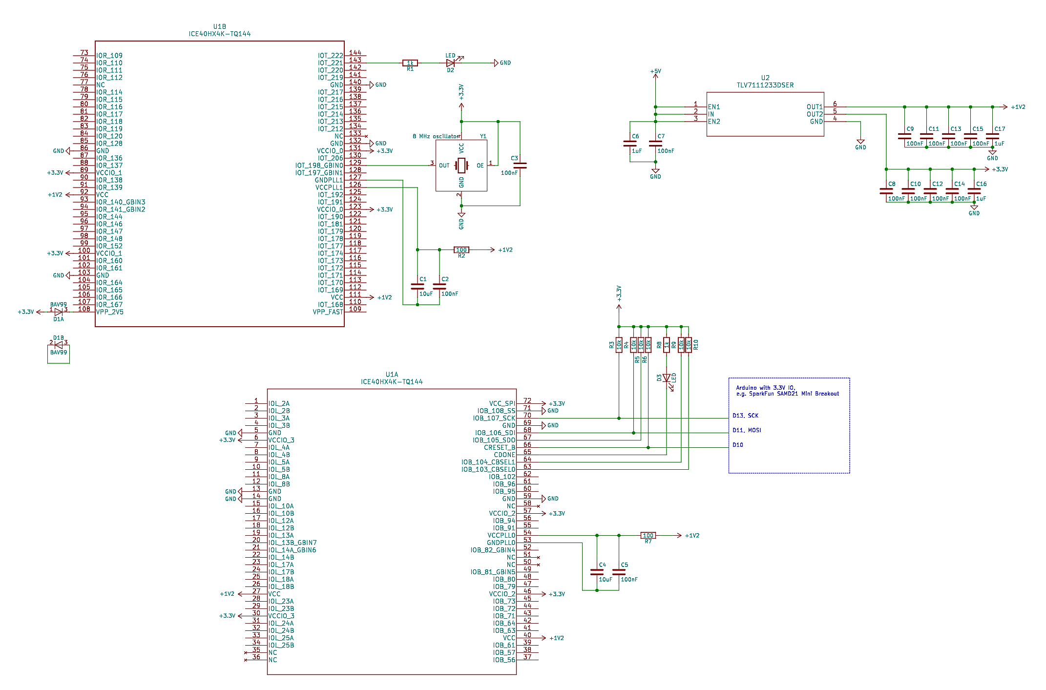
I have an additional flash and SRAM on my board, but you don't need this for a minimal test setup. This is the minimal circuit diagram how to use the FPGA (click on the image to zoom in) :
![]()
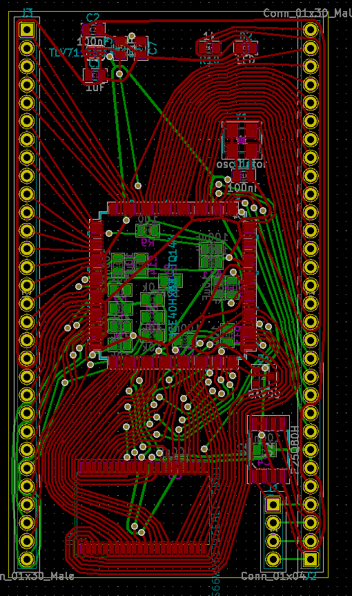
The routing was done with TopoR:
![]()
With the iCEcube2 IDE I wrote this test program:
library IEEE;
use IEEE.STD_LOGIC_1164.all;
use IEEE.numeric_std.all;

entity top is
    port (
        clk : in STD_LOGIC;
        led : out STD_LOGIC
    );
end top;

architecture Behavioral of top is
    signal blinker : natural range 0 to 25000000;
    signal blink : std_logic;

begin
    process (clk)
    begin
        if rising_edge(clk) then
            blinker <= blinker + 1;
            if blinker = 4000000 then
                blinker <= 0;
                blink <= not blink;
            end if;
            led <= blink;
        end if;
    end process;
end Behavioral;
When I compile it, I get the file "test_Implmnt/sbt/outputs/bitmap/top_bitmap.bin".
It is easy to configure the FPGA: First set the CRESET_B pin to low to reset the FPGA. Then hold down the SS pin and set CRESET_B to high, which starts the SPI slave configuration mode. You can then send the bin file data with the SDI and SCK pins.
On the Arduino side I wrote this script for the transfer:
#include <SPI.h>

#define RESET_PIN 10

#define ACK 6
#define NAK 21

const int BUF_SIZE = 128;

uint8_t buffer[BUF_SIZE];

void setup() {
  pinMode(RESET_PIN, OUTPUT);
  SerialUSB.begin(115200);

  SPI.begin();
  SPI.beginTransaction(SPISettings(1000000, MSBFIRST, SPI_MODE0));
}

void readBlock() {
  // wait for block start
  unsigned long t0 = millis();
  while (true) {
    if (SerialUSB.available()) {
      break;
    }
    unsigned long t1 = millis();
    if (t1 - t0 > 1000) {
      // timeout
      SerialUSB.write(NAK);
      return;
    }
  }

  // read data
  int received = SerialUSB.readBytes((char*) buffer, BUF_SIZE);
  if (received != BUF_SIZE) {
    // timeout
    SerialUSB.write(NAK);
    return;
  }

  // send with SPI
  SPI.transfer(buffer, BUF_SIZE);

  // acknowledge
  SerialUSB.write(ACK);
}

void loop() {
  // read command
  char cmd;
  while (true) {
    if (SerialUSB.available()) {
      cmd = SerialUSB.read();
      break;
    }
  }

  // execute command
  switch (cmd) {
    case 'r':
      // reset
      digitalWrite(RESET_PIN, LOW);
      delay(10);
      digitalWrite(RESET_PIN, HIGH);
      delay(10);
      SerialUSB.write(ACK);
      break;
    case 'b':
      readBlock();
      break;
    default:
      SerialUSB.write(NAK);
  }
}
And then I could upload the bin file with this Python script:
#!/usr/bin/python3

import serial

ACK = 6
NAK = 21

ser = serial.Serial('/dev/ttyACM0', 115200, timeout=1)

# read and evaluate response
def readResponse():
    d = ser.read(1)
    if len(d) == 0:
        raise Exception('response timeout')
    if d[0] == ACK:
        return
    if d[0] == NAK:
        raise Exception('NAK received')
    raise Exception('unkown response')

# send a command
def sendCommand(cmd):
    ser.write(cmd.encode())
    readResponse()

# send a block
def sendBlock(data):
    ser.write('b'.encode())
    for d in data:
        ser.write([d])
    readResponse()

# read file and add some bytes at the end for the required 49 clocks for configuration
inputFile = open('top_bitmap.bin', 'rb')
bufSize = 128
data = bytearray(inputFile.read()) + bytearray([0] * (bufSize * 2))

# reset FPGA
sendCommand('r')

# send data to FPGA
while len(data) > bufSize:
    block = data[:bufSize]
    data = data[bufSize:]
    sendBlock(block)
At the end of the upload the CDONE pin goes low, if there was no error. I added an LED to it which goes off when it is done.
The other LED on pin 143 blinked with 1 Hz after the configuration, as programmed in the VHDL file.
-
voltage level translators
04/13/2019 at 13:11 • 0 comments5 V to 3.3 V
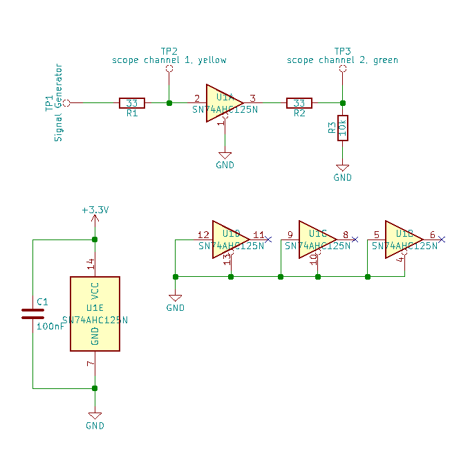
Test circuit with a SN74AHC125N, bought here, for the 5 V to 3.3 V level translation:
![]()
Signal generator: Siglent SDG1050, 50 MHz max output frequency
Oscilloscope: Agilent DSO-X 3012A, 100 MHz analog bandwith, 4 GSa/s samplerate
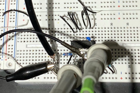
Test setup:
![]()
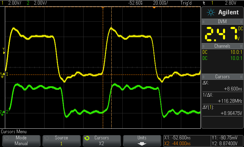
Result for 10 MHz:
![]()
Less than 10 ns propagation delay, fast edges.
3.3 V to 5 V
Result for a SN74AHCT125N, bought here, same circuit and test setup, but with 5 V supply for the buffer and 3.3 V for the signal generator, to test the 3.3 V to 5 V level translation:
![]()
A little bit slower, but still less than 10 ns propagation time and fast edges. The datasheet guarantees high level signal detection down to 3 V, but it works even with 2 V:
![]()
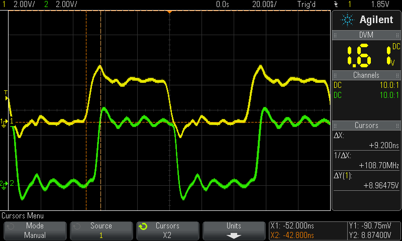
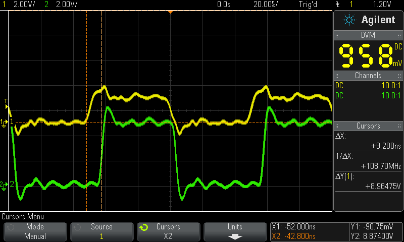
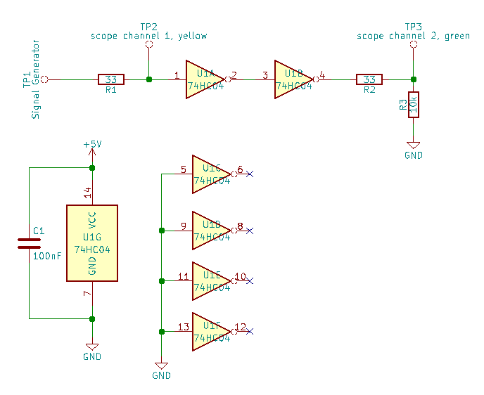
Test with a CD74HC04E hex inverter
Test circuit with a CD74HC04E, bought here:
![]()
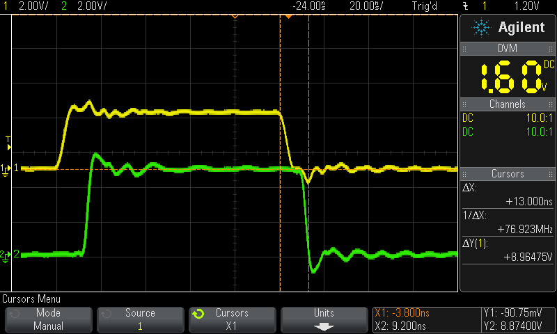
Doesn't work with 2 V for the input signal and gate propagation time is longer than 10 ns. With 3.3 V at the input and 5 V for the supply it looks like this:
![]()
Fully working example with FRAM
This is an example with the SN74AHC125N and SN74AHCT125N, and an ATmega328 and a FRAM chip. The ATmega328 is running a 5 V, and the memory with SPI port at 3.3 V. Test setup:
![]()
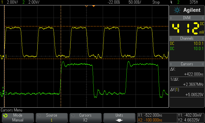
The SPI bus is running at the max possible frequency of 10 MHz. Yellow is the clock signal from the microcontroller and green the MISO signal from the memory, measured at the microcontroller input:
![]()
The combined delay of the memory IC and the gate delays of the voltage translators is less than 20 ns, good enough that the microcontroller can cleanly sample the MISO signal at rising clock edge.
-
SPI-Flash Test
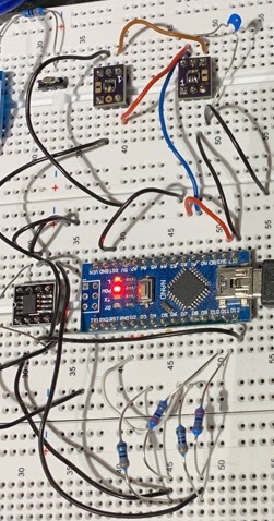
04/05/2019 at 14:58 • 1 commentI bought the 8 Mbit flash P25Q80H-SSH-IT at lcsc.com for $0.10 if you buy 10. First I tried it with this circuit on a breadboard:
![]()
The numbers are the pin numbers on a Arduino Nano, which runs with 5 V, so I used the resistor dividers for scaling down the output voltage. The 3.3 V output from the flash was enough for the MISO line, but it didn't run stable, sometimes bits were missing when I tried to read the chip ID. And it got worse when I tried to measure the clock with the scope, probably because of the increased capacity and slower rising and falling times.
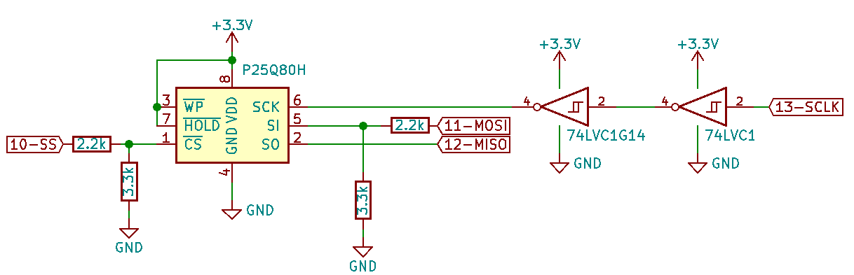
To fix this, I added two 74LVC1G14 schmitt trigger inverter ($0.04 at lcsc.com) :
![]()
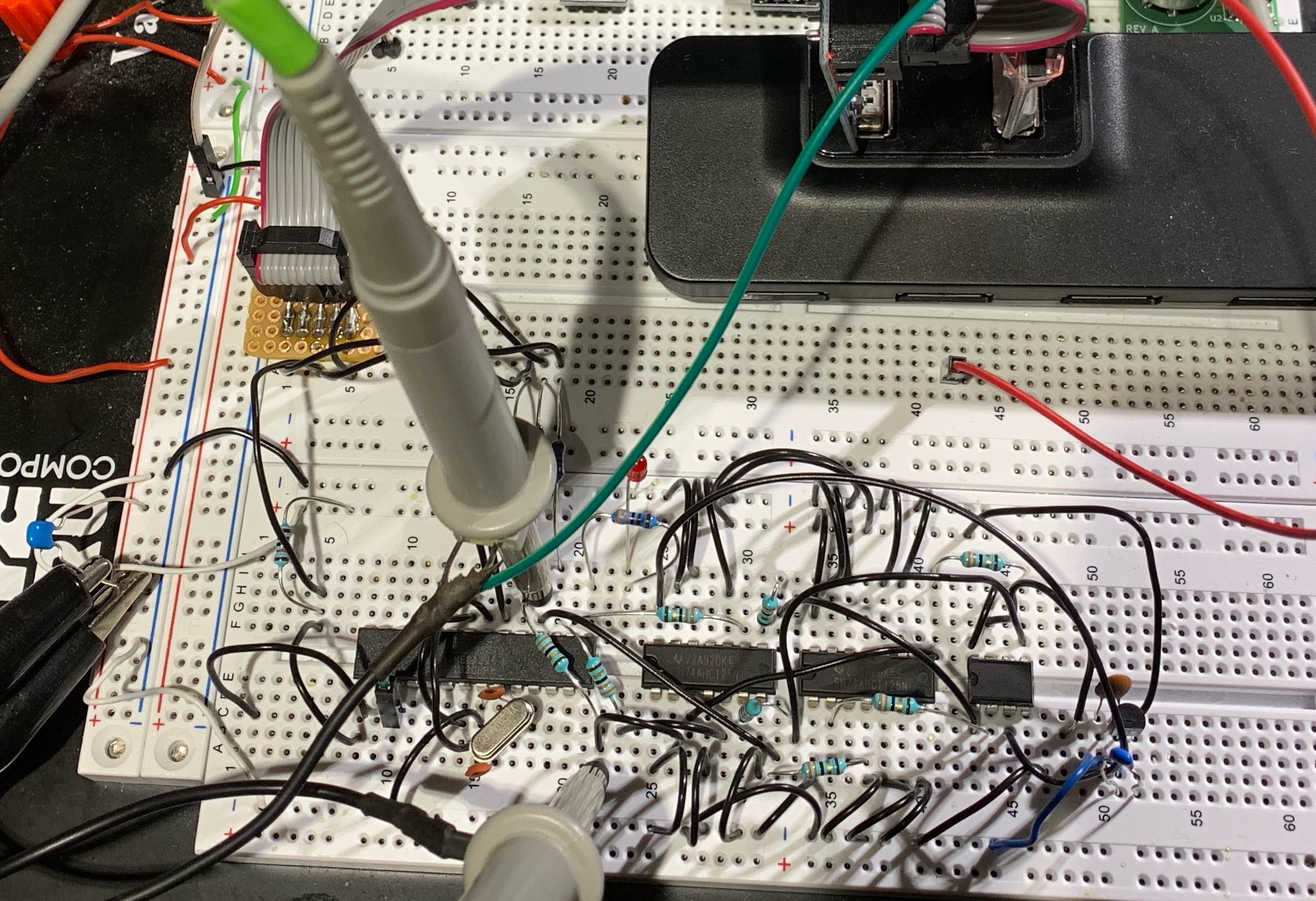
The datasheet says it allows 5 V at the input, even with 3.3 V supply voltage, for using it as a voltage converter. This is the test setup, with an additional 100 nF capacitor for the supply voltages for the inverters and the flash:
![]()
The other pins are not critical, because they are only sampled at rising clock and changed at falling clock. This is the full script with a write test at the start, and then read tests in the loop:
#include <stdint.h>
#include <SPI.h>

#define PAGE_SIZE 256

uint8_t data[PAGE_SIZE];
const int csPin = 10;

unsigned long startTime;

void startMeasure() {
  startTime = millis();
}

void error(const char* text) {
  Serial.println(text);
  while (1) {}
}

void stopMeasure(const char* text) {
  unsigned long currentTime = millis();
  unsigned long elapsedTime = currentTime - startTime;
  Serial.print(text);
  Serial.print(": ");
  Serial.print(elapsedTime);
  Serial.println(" ms");
}

void sendOneByteCommand(uint8_t command) {
  digitalWrite(csPin, LOW);
  SPI.transfer(command);
  digitalWrite(csPin, HIGH);
}

uint8_t readStatusRegister() {
  digitalWrite(csPin, LOW);
  SPI.transfer(0x05);
  uint8_t result = SPI.transfer(0);
  digitalWrite(csPin, HIGH);
  return result;
}

void waitUntilWriteDone() {
  // wait until WIP bit is 0
  while (readStatusRegister() & 1) {}
}

void reset() {
  sendOneByteCommand(0x66);
  sendOneByteCommand(0x99);
  delay(20);
}

void readId() {
  digitalWrite(csPin, LOW);
  SPI.transfer(0x9f);
  uint8_t manufacturerId = SPI.transfer(0);
  uint8_t memoryType = SPI.transfer(0);
  uint8_t memoryDensity = SPI.transfer(0);
  digitalWrite(csPin, HIGH);

  Serial.print("manufacturer ID: 0x");
  Serial.print(manufacturerId, HEX);
  Serial.print(", memory type: 0x");
  Serial.print(memoryType, HEX);
  Serial.print(", memory density: 0x");
  Serial.println(memoryDensity, HEX);
  if (manufacturerId == 0x85 && memoryType == 0x60 && memoryDensity == 0x14) {
    Serial.println("ID ok");
  } else {
    error("wrong ID");
  }
}

void writeEnable() {
  sendOneByteCommand(0x06);
}

void writeAddress(uint32_t address) {
  SPI.transfer((address >> 16) & 0xff);
  SPI.transfer((address >> 8) & 0xff);
  SPI.transfer(address & 0xff);
}

// erase the whole chip
void chipErase() {
  writeEnable();
  sendOneByteCommand(0x60);
}

// erase one page
void pageErase(uint32_t address) {
  writeEnable();
  digitalWrite(csPin, LOW);
  SPI.transfer(0x81);
  writeAddress(address);
  digitalWrite(csPin, HIGH);
}

// program one page
// note: changes the content of the data array
void pageProgram(uint32_t address, uint8_t* data) {
  writeEnable();
  digitalWrite(csPin, LOW);
  SPI.transfer(0x02);
  writeAddress(address);
  SPI.transfer(data, PAGE_SIZE);
  digitalWrite(csPin, HIGH);
}

// reads data from flash
unsigned long readData(uint32_t address, uint8_t* data, uint32_t size) {
  digitalWrite(csPin, LOW);
  SPI.transfer(0x03);
  writeAddress(address);
  SPI.transfer(data, size);
  digitalWrite(csPin, HIGH);
}

void setup() {
  pinMode(csPin, OUTPUT);
  Serial.begin(115200);

  SPI.begin();
  SPI.beginTransaction(SPISettings(8000000, MSBFIRST, SPI_MODE0));

  reset();
  readId();

  // erase whole chip
  chipErase();
  startMeasure();
  waitUntilWriteDone();
  stopMeasure("chip erase time");

  // verify
  readData(0, data, PAGE_SIZE);
  for (int i = 0; i < PAGE_SIZE; i++) {
    if (data[i] != 0xff) {
      error("chip erase verify error");
...
Read more -
TopoR test
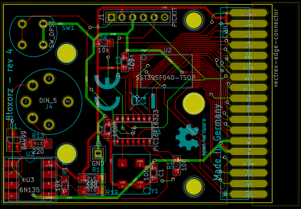
03/14/2019 at 08:49 • 0 commentsJust a quick test of the program TopoR. This is my Bloxorz cartridge, manually routed in KiCad:
![]()
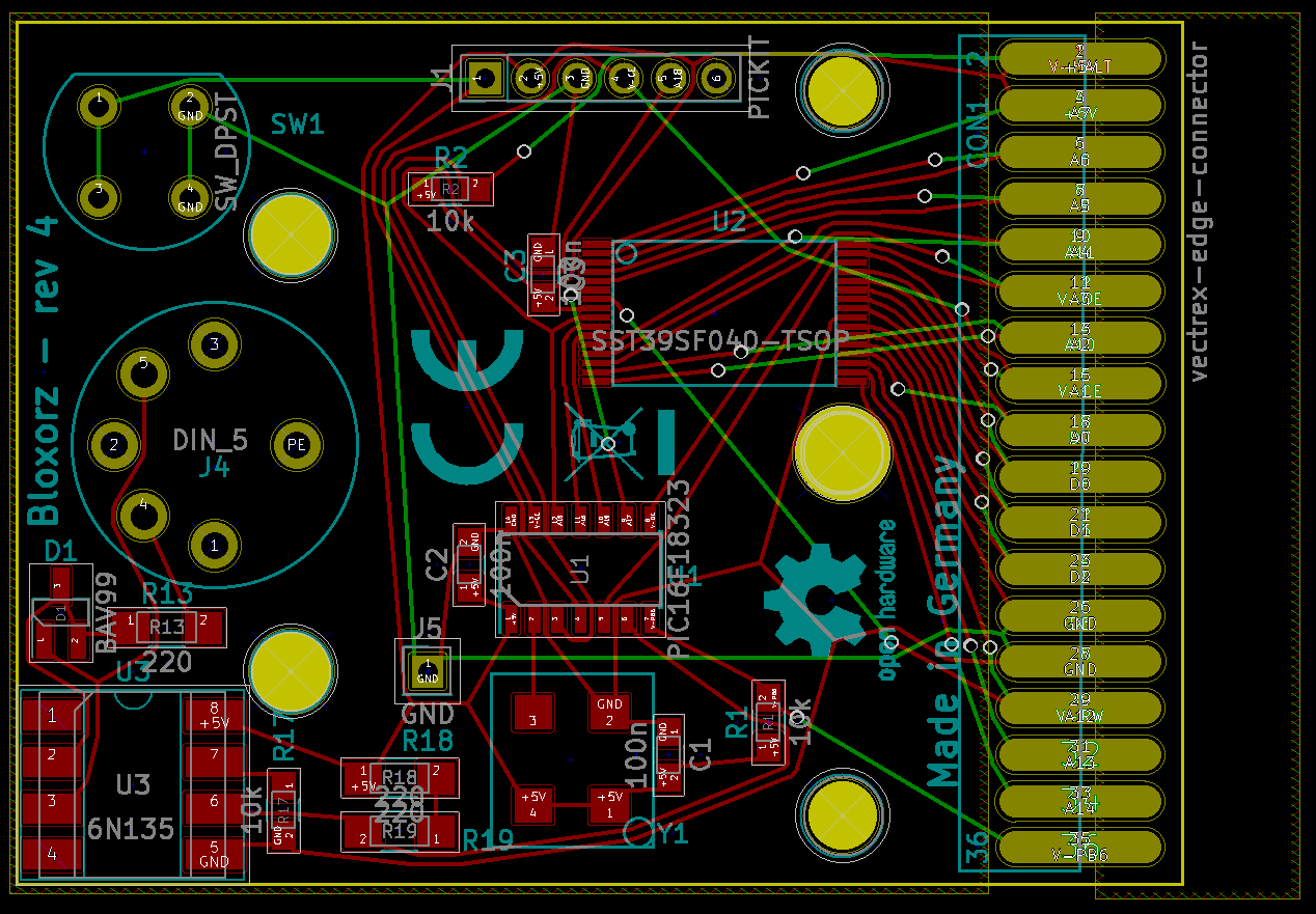
And this is the routing with TopoR:
![]()
Looks very good, 100% routed, less vias (20 instead of 35) and shorter connections. I have to look in more detail into it how to specify different trace width for the power supply, but it is much better and easier than manual routing, or the KiCad auto-router. You can download a free trial of the program from their website, and a lite version with limited number of connections.
-
potentiometer on breadboard
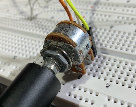
12/26/2018 at 13:59 • 0 commentsJust a quick tip: If you use a stereo potentiometer with PC (printed circuit board) pins termination style, for example this one, then you can just plug it into a breadboard and it is very stable, perfect for prototyping. No need for soldering wires or any extra breakout board. The 2 potentiometers are in parallel, so use a 20 k pot, if you need 10 k.
This image shows a similar potentiometer, I can't find the exact same model, but the datasheet of the Bourns potentiometer shows (nearly) 0.2" pitch as well, so it should work the same.
![]()
-
Write better Arduino code with advanced C++ features
08/09/2018 at 22:19 • 0 commentsThe Arduino IDE allows to use advanced C++ features like classes and operator overloading. There are not many Arduino sketches that uses these features, but it can help to make your code more readable and maintainable.
This is an example how to make the standard "blink" example easier to read:
// general class to simplify the syntax to write to a pin
class PinOut {
  public:
    PinOut(uint8_t pin): m_pin(pin) {
      pinMode(pin, OUTPUT);
    }

    PinOut& operator= (uint8_t state) {
      digitalWrite(m_pin, state ? HIGH : LOW);
      return *this;
    }

  private:
    uint8_t m_pin;
};

// example usage: create a "led" object, which uses the pin number LED_BUILTIN
PinOut led(LED_BUILTIN);

void setup() {}

// much easier to read "blinking" example
void loop() {
  led = 1;
  delay(1000);
  led = 0;
  delay(1000);
}
So instead of writing "digitalWrite(LED_BUILTIN, HIGH)" whenever you want to light up the LED, now you can just write "led = 1". You can create more objects for other pins as well, which makes your program much easier to read.
Left as an exercise to the reader to implement a class for reading pins.
You could outsource the class in a separate library, then you need just an include to use the class, without always copying the class declaration in your sketch.
This example was inspired by the PortOut class of the mbed framework:
https://os.mbed.com/handbook/PortOut
It can be even faster than the standard function. cosnider this code:
void loop() {
  while (true) {
    digitalWrite(31, HIGH);
    digitalWrite(31, LOW);
  }
}
On an Arduino Zero it creates a square wave of 330 kHz on pin 31.
In this posting someone wrote a digitalWrite_fast function. This improves the speed and it runs with about 1.4 MHz. But with a C++ class, the lookup for the register can be cached in the constructor. And with overloading the "int" cast operator, the value of the port can be read by just specifying the object (this class assumes the pinMode is set outside as usual) :
// class definition
class FastPin {
  public:
    // cache the ports and bit mask to change and read the port
    FastPin(int pin) {
      m_portSet = &PORT->Group[g_APinDescription[pin].ulPort].OUTSET.reg;
      m_portClear = &PORT->Group[g_APinDescription[pin].ulPort].OUTCLR.reg;
      m_inReg = &PORT->Group[g_APinDescription[pin].ulPort].IN.reg;
      m_mask = (1ul << g_APinDescription[pin].ulPin);
    }

    // operator= overload, to write to the pin
    inline FastPin& operator= (uint8_t state) {
      if (state) *m_portSet = m_mask; else *m_portClear = m_mask;
      return *this;
    }

    // int cast operator overload, to read the pin
    inline operator int() const { return ((*m_inReg) & m_mask) > 0; }

  private:
    volatile uint32_t* m_portSet;
    volatile uint32_t* m_portClear;
    volatile uint32_t* m_inReg;
    uint32_t m_mask;
};

// example how to use it
#define BUTTON_PIN 24
#define TOGGLE_PIN 31
FastPin someButton(BUTTON_PIN);
FastPin myPin(TOGGLE_PIN);

void setup() {
  pinMode(BUTTON_PIN, INPUT_PULLUP);
  pinMode(TOGGLE_PIN, OUTPUT);
}

void loop() {
  if (someButton == LOW) {
    while (true) {
      myPin = HIGH;
      myPin = LOW;
    }
  }
}
This toggles the pin with 3.4 MHz, when the button is pressed.
-
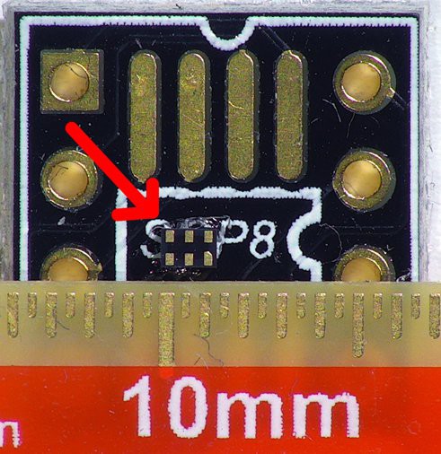
How to solder a 1 mm x 1.5 mm, 6 pad USON package IC
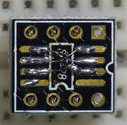
06/22/2018 at 16:51 • 3 commentsThis page describes how I tested a TPS3420 reset chip on a breadboard. First I glued the chip in dead bug style on a SMD adapter board:
![]()
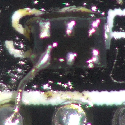
Then I tinned the pads of the IC and of the SMD adapter (the pink things at the left side are my fingers) :
![]()
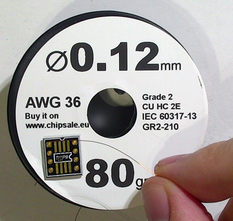
For connecting the pads of the IC to the pads of the adapter, I used enameled wire, AWG 36 (0.12 mm diameter) :
![]()
To remove the enamel, I used a scrap board and some more tin. The lacquer melts after some time and the wire gets tinned as well:
![]()
![]()
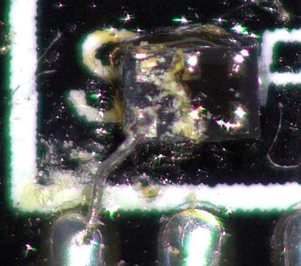
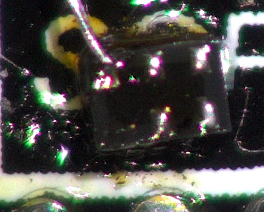
Then I soldered one side of the wire to the SMD pad, first, and cut it to length. The scratches on the IC are in the flux residue, when I tried to position the wire with a scalpel. You need eagle eyes or a good microscope to do this.
![]()
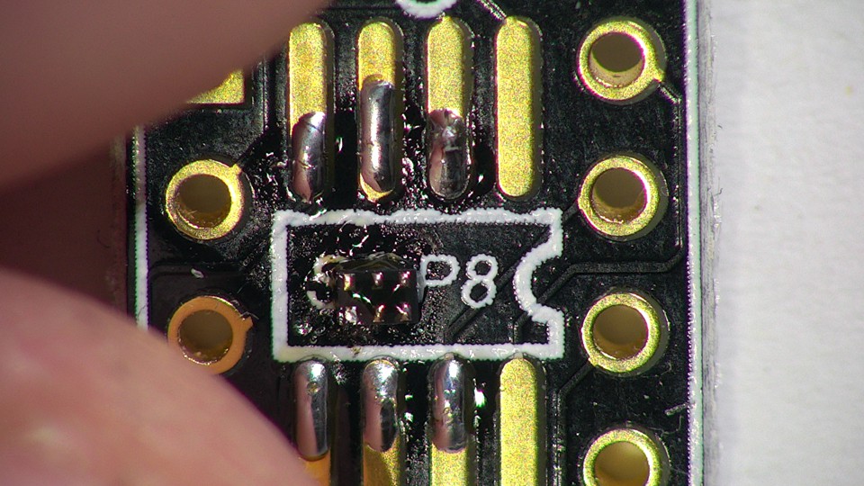
Then I soldered the other end the IC pad:
![]()
If you move the soldering iron to strong, or apply too much heat or for too long, pads disappear, as happened for me. Buy some spare part.
![]()
Finally I plugged in some pin headers in a breadboard and placed the SMD adapter on it. This guarantees that the pin headers are straight when soldering.
![]()
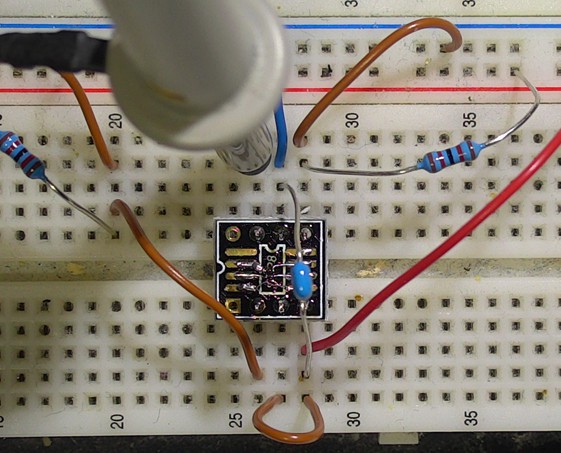
Connected in a testing circuit:
![]()
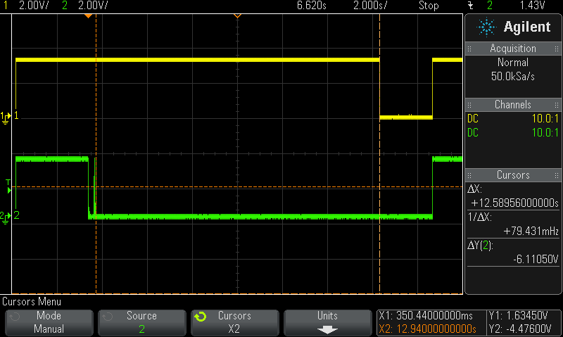
Testing: green is both button inputs and yellow is the reset output.
![]()
As specified in the datasheet, reset triggers after holding down both button inputs for 12.5 s, with TS=VCC configuration.
-
eBay Watt Meter review
02/12/2018 at 22:40 • 0 commentsI bought this watt meter from eBay. The case is a nice extruded aluminium case, but it is unusable for low currents. For example it shows 30 mA for a 100 mA load, tested with a passive resistor:
![]()
And still about 28% error for 1 A, tested with a passive resistor as well:
![]()
I guess for higher currents it gets better.
Internally it uses a shunt in the ground path, which is called low-side current measurement. This might be a problem if you have other things connected to ground to the device you are measuring:
![]()
It works down to about 4.7 V. But it should be possible to desolder the red wires from the board and solder a wire for an external power supply to the PCB.
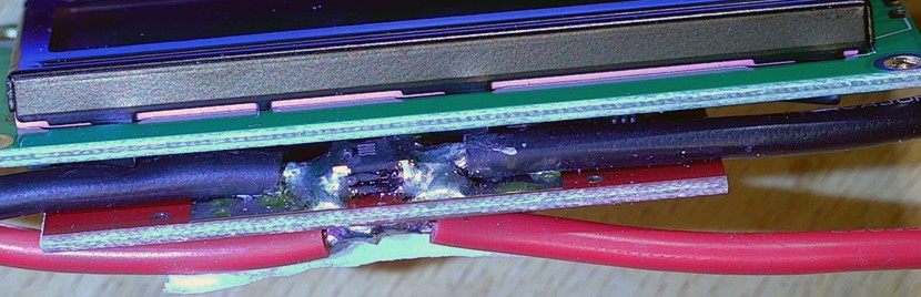
The display is soldered to the board, so I can't see details of the circuit:
![]()
Conclusion: if you want to measure high currents above 1 A and don't care about accuracy, you can use this. Otherwise don't buy it.