update: this truckload of treasure was Craigslisted onto a stoked local person and his father, both of whom were excited for the possibilities. Consider giving away your old stuff, you might make someone happy.
Danica and I are preparing to move east to pursue new and interesting opportunities. As part of this transition, we're doing a good bit of downsizing. I've decided to rid myself of a lot of the random electronics (and electronics-adjacent) junk I've collected over the last few years. Some of this isn't worth much, but you may find some useful gems and I'm not interested in splitting the lot up at this point. If you are interested, live in the US, and are willing to cover postage, I will send it to you for free.
I'm still figuring out exactly what the box will contain, but at a minimum:
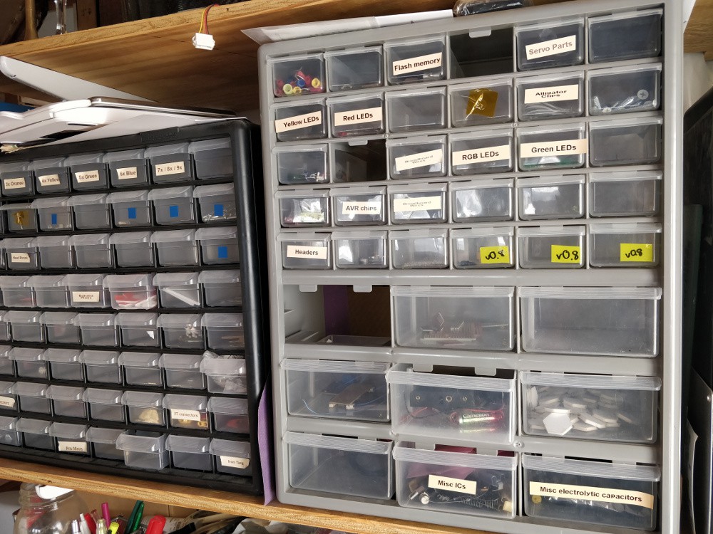
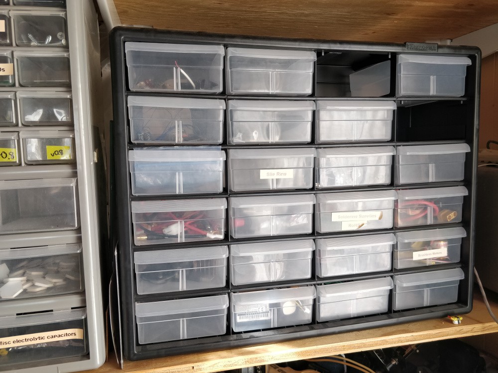
three Akro-Mils clear sliding drawer bins filled with random and interesting parts
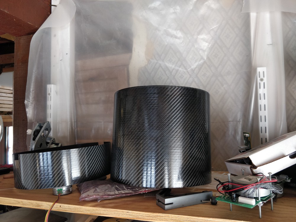
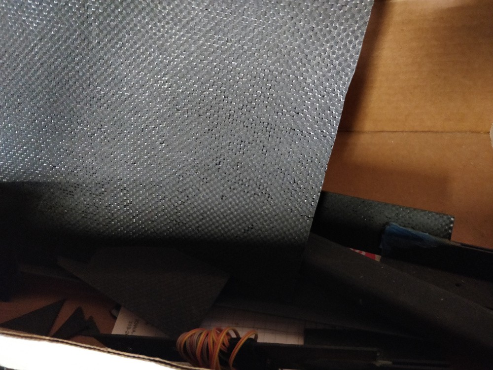
a selection of DragonPlate CFRP scraps of various sizes
two somewhat flexible large diameter CFRP tubes
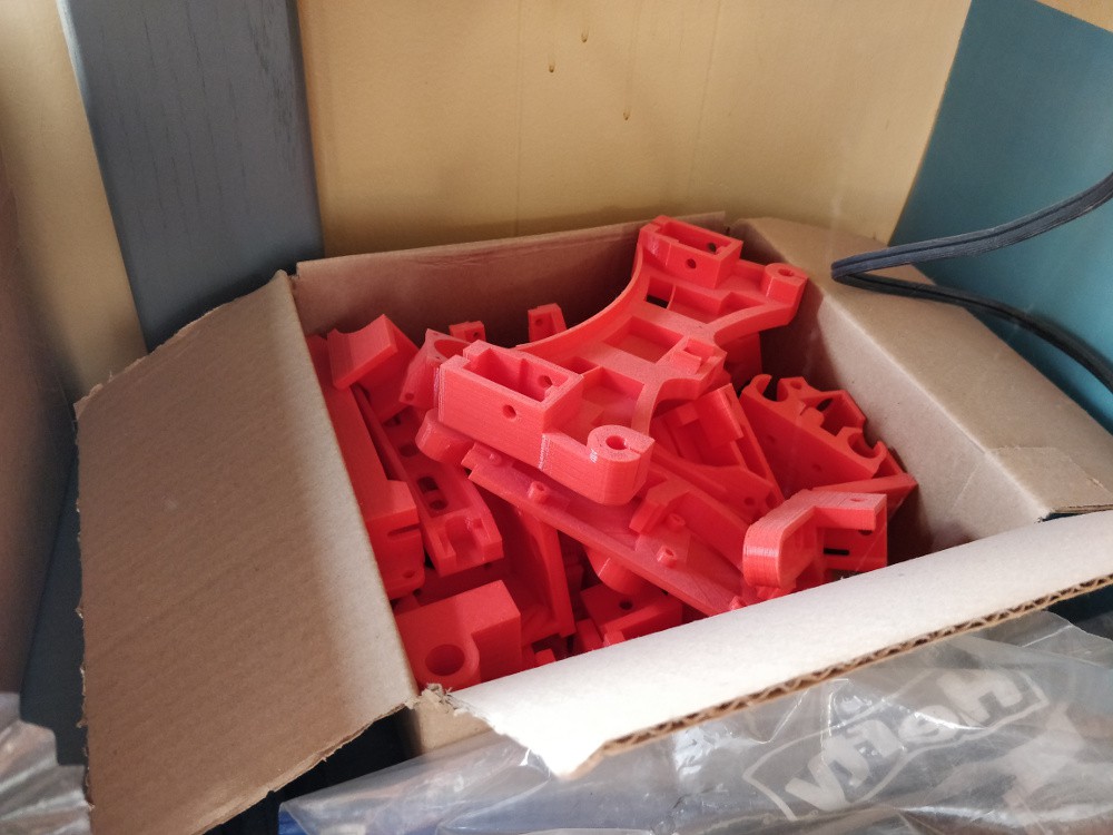
a partial Reprap Wilson II 3D printer (all the 3D printed parts plus black anodized extrusion, but nothing else)
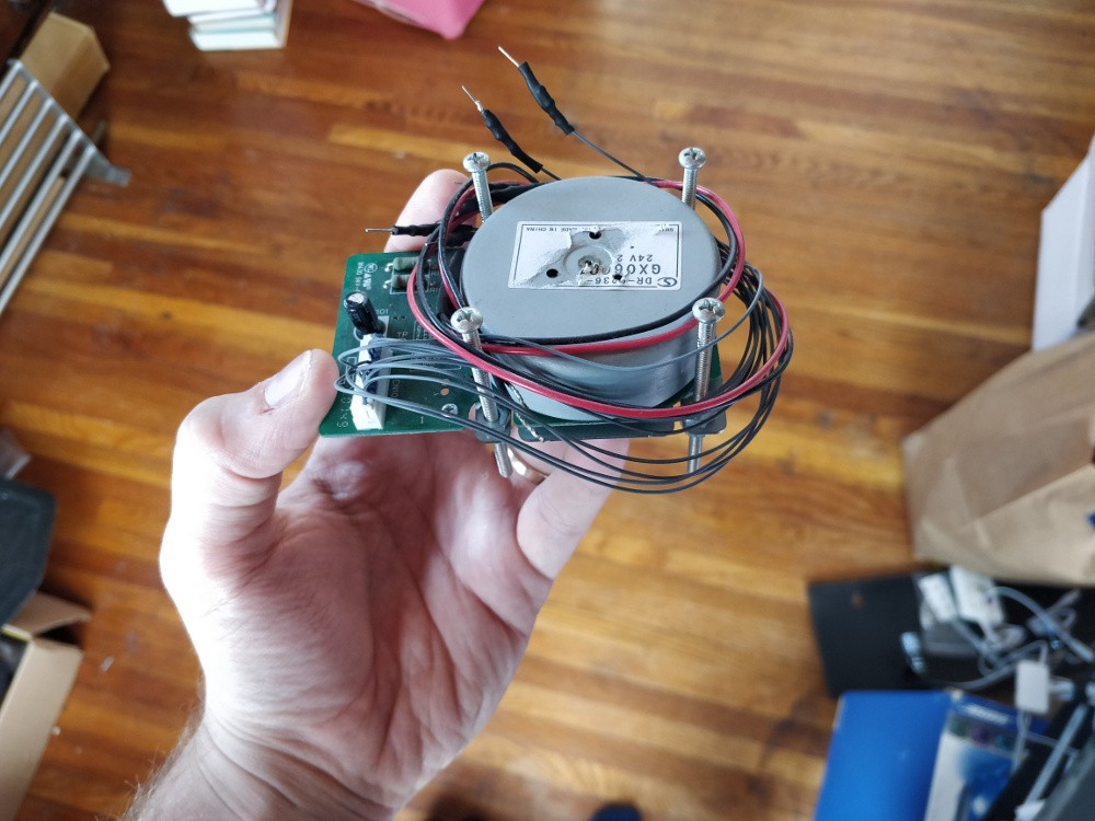
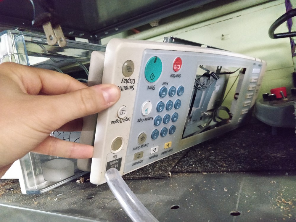
all of the interesting bits out of an office photocopier: gears, shafts, steppers, servos, first surface mirrors, sensor, control panel, etc.
a PiDP-8 kit, with the switch soldering already done
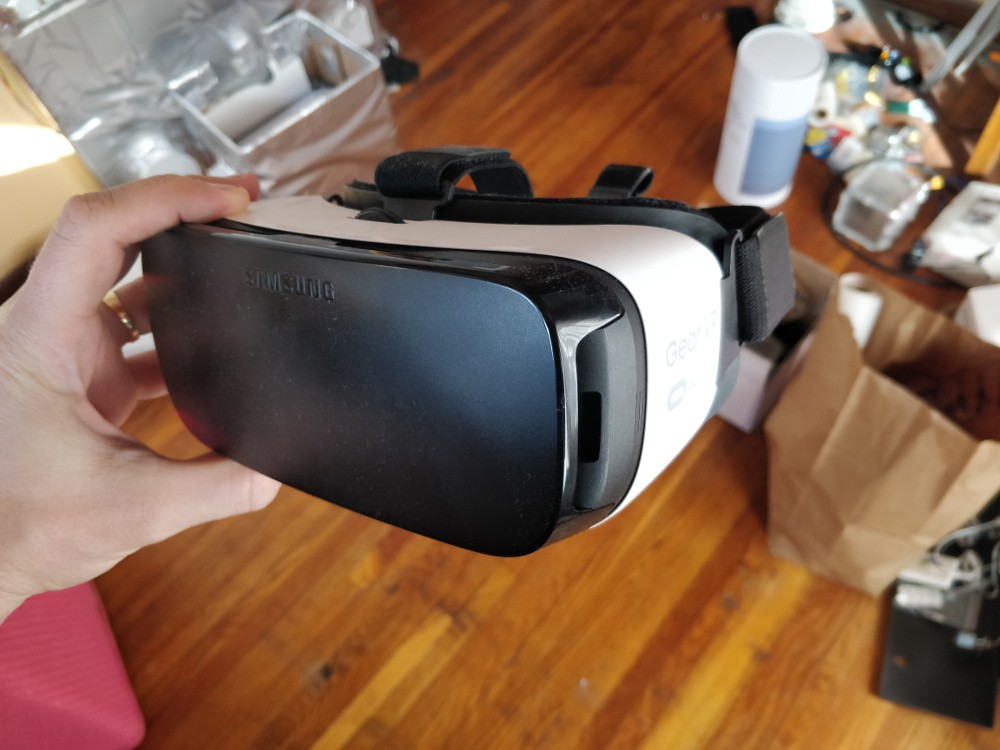
a samsung galaxy gear VR headset, designed for a phone I never owned
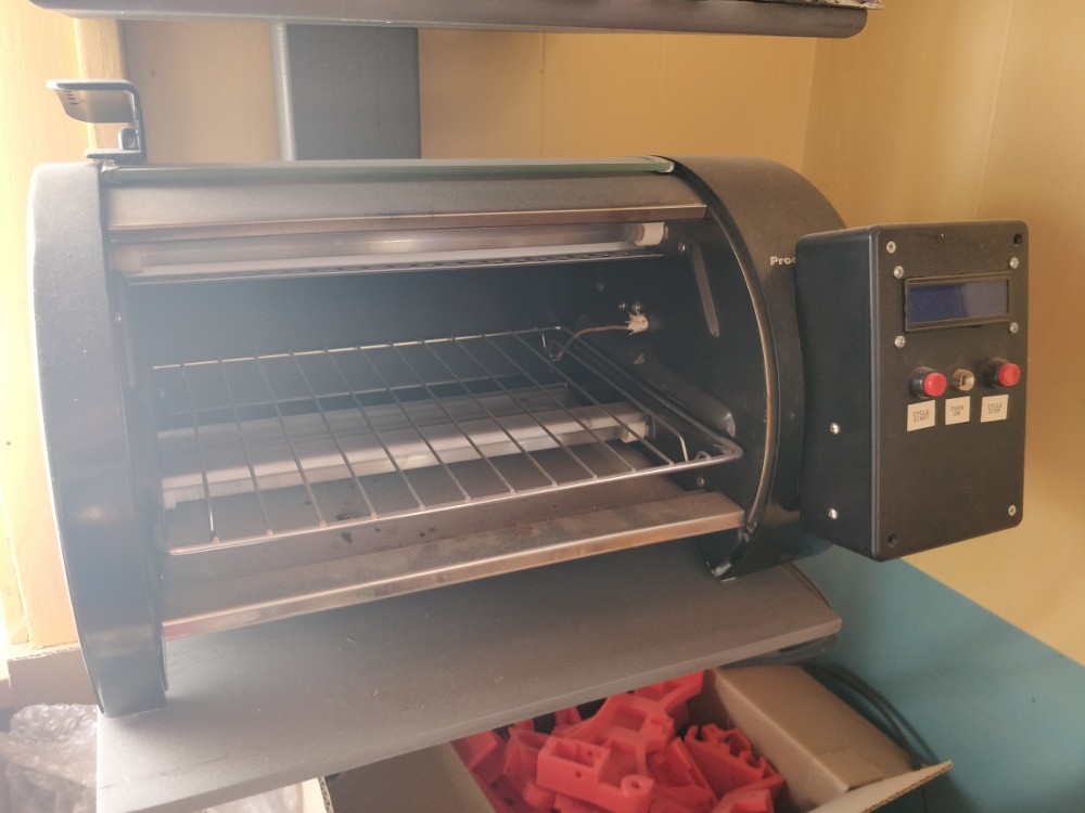
my old modified toaster oven reflow setup, which works but you should be careful with and probably reprogram (it's powered by an Arduino of some kind)
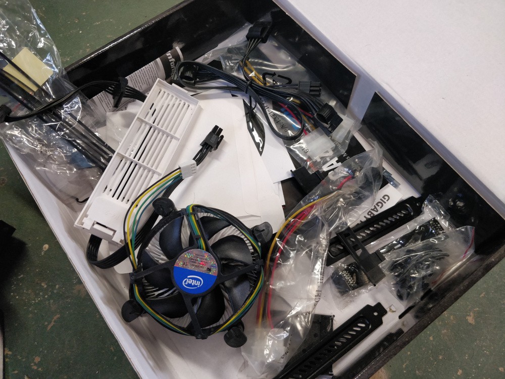
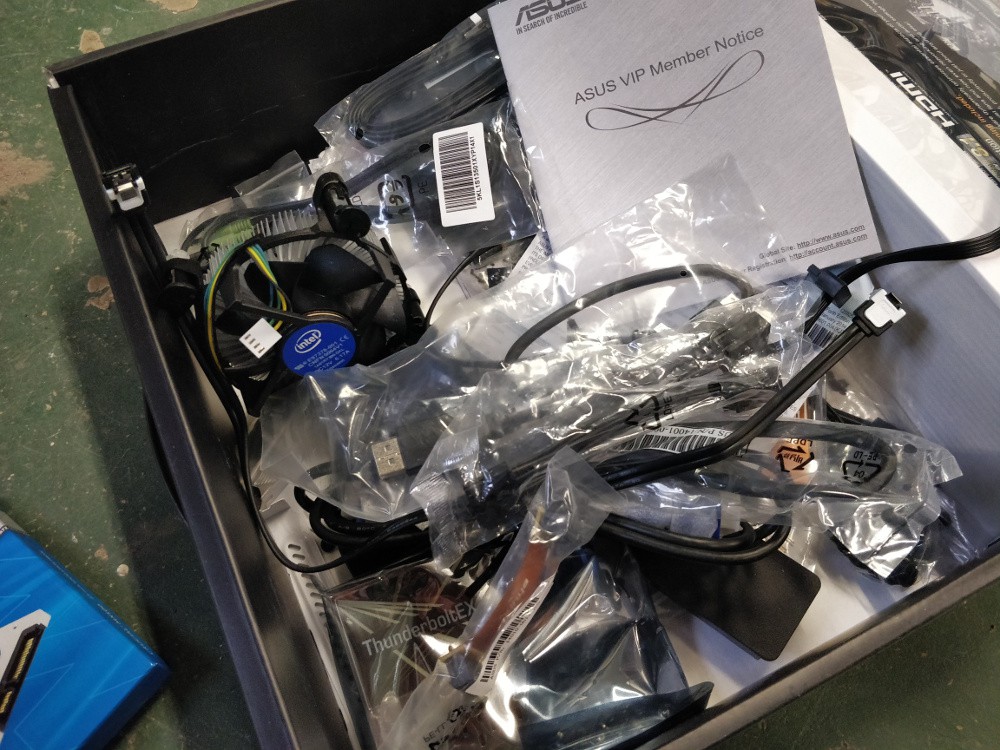
a selection of homebuilt PC extras, including a few stock Intel coolers and lots of misc cables
a beefy-AF transformer of unknown rating
a nice pair of HeNe (632nm) laser safety goggles
a few under-counter LED lights
the guts from an old-school industrial 900 MHz industrial data radio
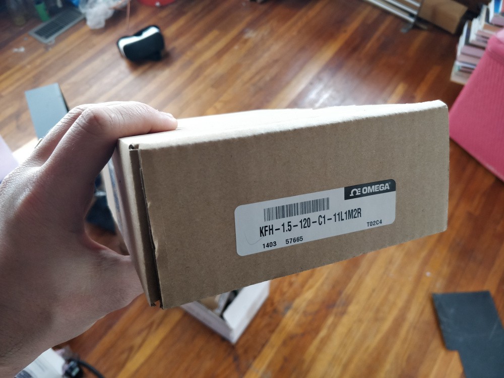
a box of ~10 Omega pre-wired strain gages (these list at $10 ea!)
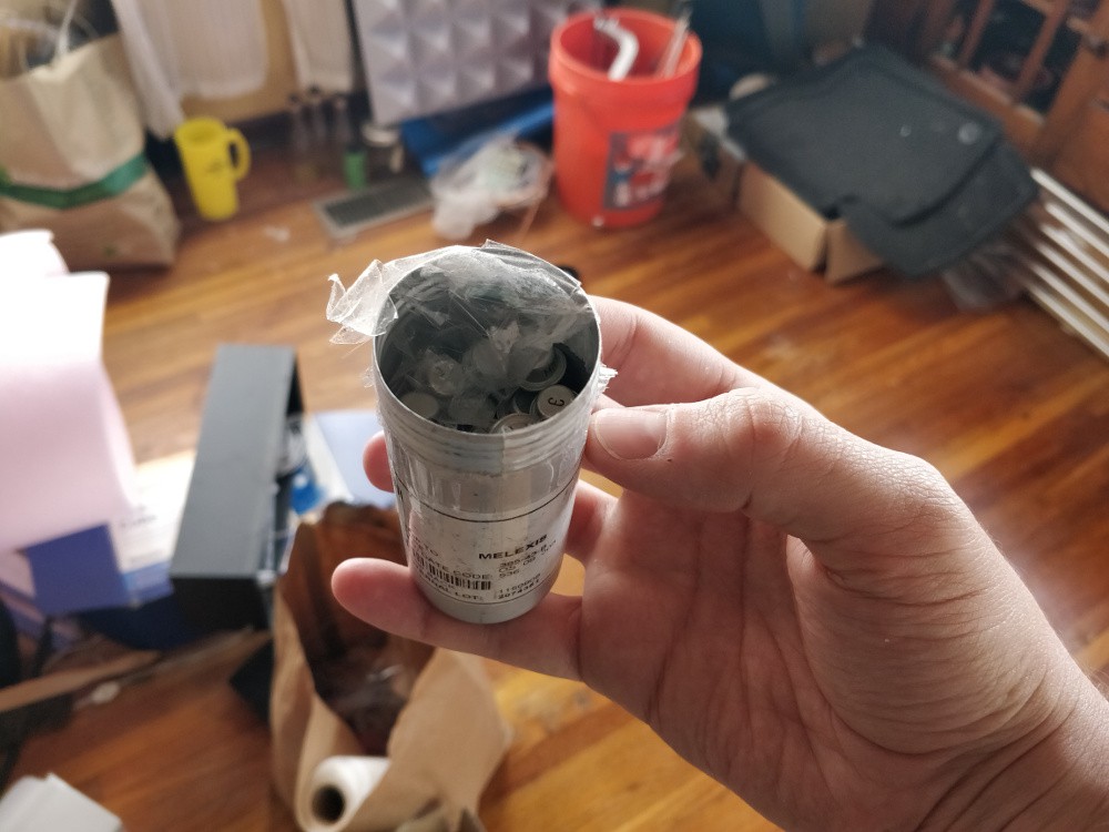
a pile of germanium transistors
My guess is the box will weigh in the 20-30 kg range, so UPS thinks it will cost around $100 to ship. If you're interested, write me a note: zachary dot fredin at gmail dot com. Otherwise, most of this will become e-waste by late May.
My feelings on 'badgelife' are neutral. I like that more people are getting in to PCB art and electronics. But personally, the only electronic conference badges I really enjoy are the ones I build myself (or at least physically customize). Most of the badges I get are worn for a few hours until they get too heavy and annoying, and then they become e-waste. And it's not my preference to let someone else design the hardware and spend my time hacking by writing code. That's my least-favorite part of any project!
But the trend towards taking copyrighted work, mashing it into an EDA tool, and building a few hundred badges or add-ons to sell online or at a conference? I find that lazy and disrespectful. Okay, copy some popular cartoon figure and make a few boards for yourself. But don't sell them en masse! Please, at the very least, come up with an original design!
edit: thank you all for reminding me why hackaday.io comment sections are amazing, I'm sure the same thing would *not* have happened on the main site :-/
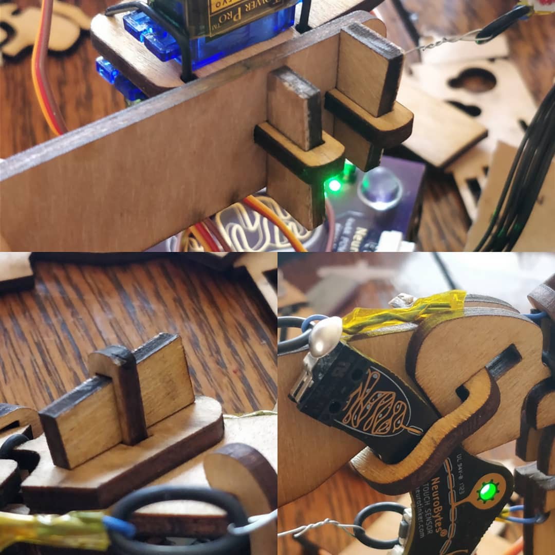
On a few occasions I have had the need to secure something to a flat bit of laser cut wood. In all cases, I created precise shapes that allow me to rigidly and accurately grip the object while not depending on the exact dimensions of the cuts themselves. The method requires final alignment to be performed during assembly, but does allow for post-assembly re-alignment and doesn't require any adhesives or fasteners. A few examples from a recent #NeuroBytes patellar reflex model iteration:
The top image is a simple T-joint, used to connect two right angle bits of 3.2mm aircraft plywood. The middle piece goes through the base in two spots and has cutouts for wedges, which are inserted and tightened during assembly to pull the joint tight. The angle isn't exactly 90 degrees due to the aforementioned kerf taper, but it works well enough for this application (a mounting plate for a demonstration model).
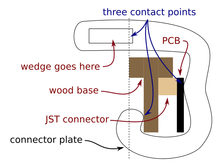
The lower images show a second joint from two sides. In this case, I needed to precisely locate a Touch Sensory Neuron with respect to the patellar tendon (the blue wire and O-ring assembly). I didn't want to modify the circuit board at all, and the exact orientation of the snap-action switch at the end of the PCB is critical to proper functionality of the model. Since the tendon is made by the end user and may vary slightly in length, part of the leg adjustment process requires the switch orientation to be adjustable, lockable, and potentially re-adjustable down the road. A cross plate with a few machine screws would have done the trick, but this method avoids the need for a screwdriver and easily lost hardware. I call the weird curved clampy bit the 'connector plate'. Not a great diagram but hopefully you get the idea. The wood base has several layers, and you have to imagine that the leftmost layer extends out towards the viewer along the dashed line. That way, when a wedge is inserted into the rectangular 'wedge goes here' slot, it pushes the upper bit of the connector plate to the left as its driven into place, clamping the board securely in place. I really should reference a side view or 3D model with this sectional image, but... here we are.
During installation, the connector plate slides in from the bottom (which is open and rotates into position, pivoting on the lower 'catch'. To ensure clearances with the holes in the wood base, I keep track of the connector plate's position extremes on the wood base using guides in Inkscape. Rotating the connector plate like this is a synch if you just move the cross symbol to change the center of rotation to the bottom contact point: Note that in the third frame, I actually translated the connector plate up a bit so one of the corners can clear. This is much easier during real life assembly; you really just need to be sure everything clears at all points during the rotation/translation, as manual assembly makes combining both movements quite intuitive.
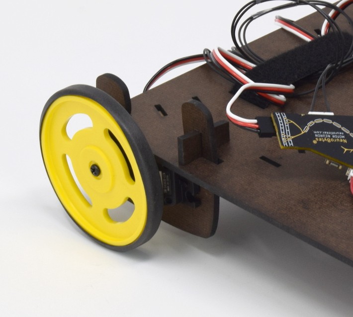
I used a similar method to hold the servos on for the latest NeuroBuggy design. Again, I needed to secure an object (in this case, a continuous rotation servo) to a flat laser-cut sheet. The object needed to be adjustable (toe angle!) and quite secure, but also removable. The connector plate is bigger but otherwise similar to the previous example -- it slides in from the rear of the car, rotates into position, and gets secured by a wedge:
This method is still very much a work in progress. I think a lot of optimization could be done to reduce the material requirement and cut length; for example, the width ratios of the tenons and slots could be standardized (probably based on a woodworking joinery book's advice), and the curved shape of the connector plate itself could probably be generated parametrically once a few constraints are figured out. The wedges are also probably beefier than needed and the angles could be optimized. But it's a good start -- feels good to assemble something without glue or fasteners!
[EDIT: I didn't have the form configured right and folks couldn't access the questions. That has been fixed, so try the link again!]
We're headed back for #NeuroBytes EMC testing next week (unintentional radiator) and the chamber requires a 2-hour minimum reservation. If you have a project that you are considering commercializing, I'll run a pre-test scan for you FOR FREE! Some requirements:
I prefer to only work with open source projects, and I want to share the results publicly. EMC testing is expensive and mysterious (at least for hobbyists), and building a public record of known-good / tested boards would be a great thing for the community.
Time is short. We are looking at Friday, February 16th, at 8AM in Minneapolis, MN. So you need to be ready to ship your project to me NOW.
I will need you to provide a self-addressed and postmarked envelope for return shipment.
Tests sweep from 30 MHz to 1 GHz. Standard unintentional radiator stuff. That means no radios -- ESP32, ESP8266, Bluetooth, Wifi, etc. Sorry folks.
Your project needs to set up and tear down quickly. As in, I plug it in (or insert batteries) and put it in the chamber, and we go. 5 minutes max.
This is just a pre-test -- you'll get a report but it won't give you certification.
If you're interested, fill out this Google Form and we'll start the conversation. Again, time is of the essence here.
Yes, it is broken. Step One is to accept this fact:
Above: a $5 Linux computer that uses 2mm header pins, meaning it requires a $10 - $15 dock to use.
Step Two is to bitch about the problem on Hack Chat (you have to scroll back a few weeks to see the post). Half an hour later, be gracious when @davedarko throws together a quick PCB design and sends you the @oshparkpurchase link. Get stoked and order the boards immediately (including one free!):
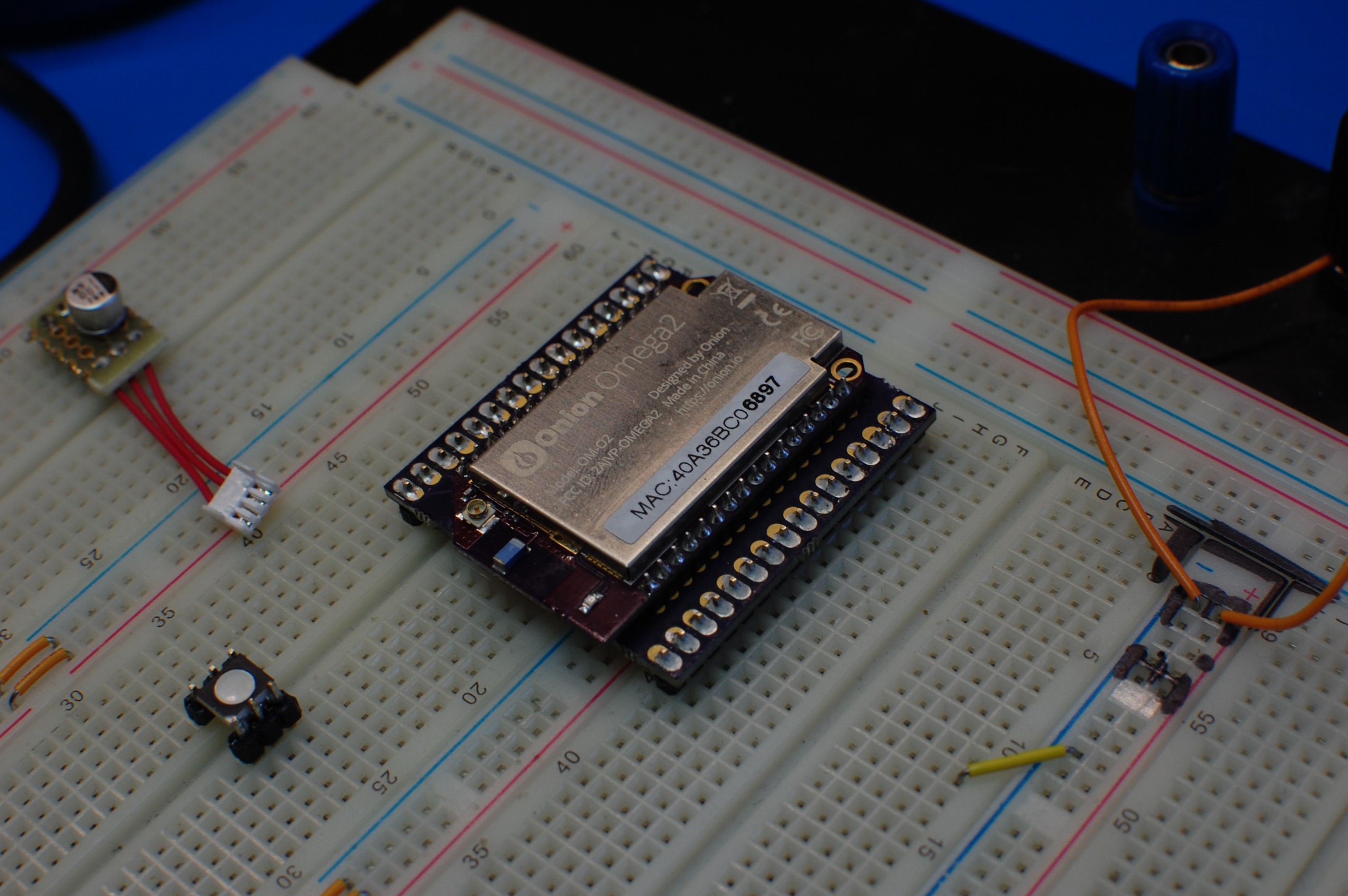
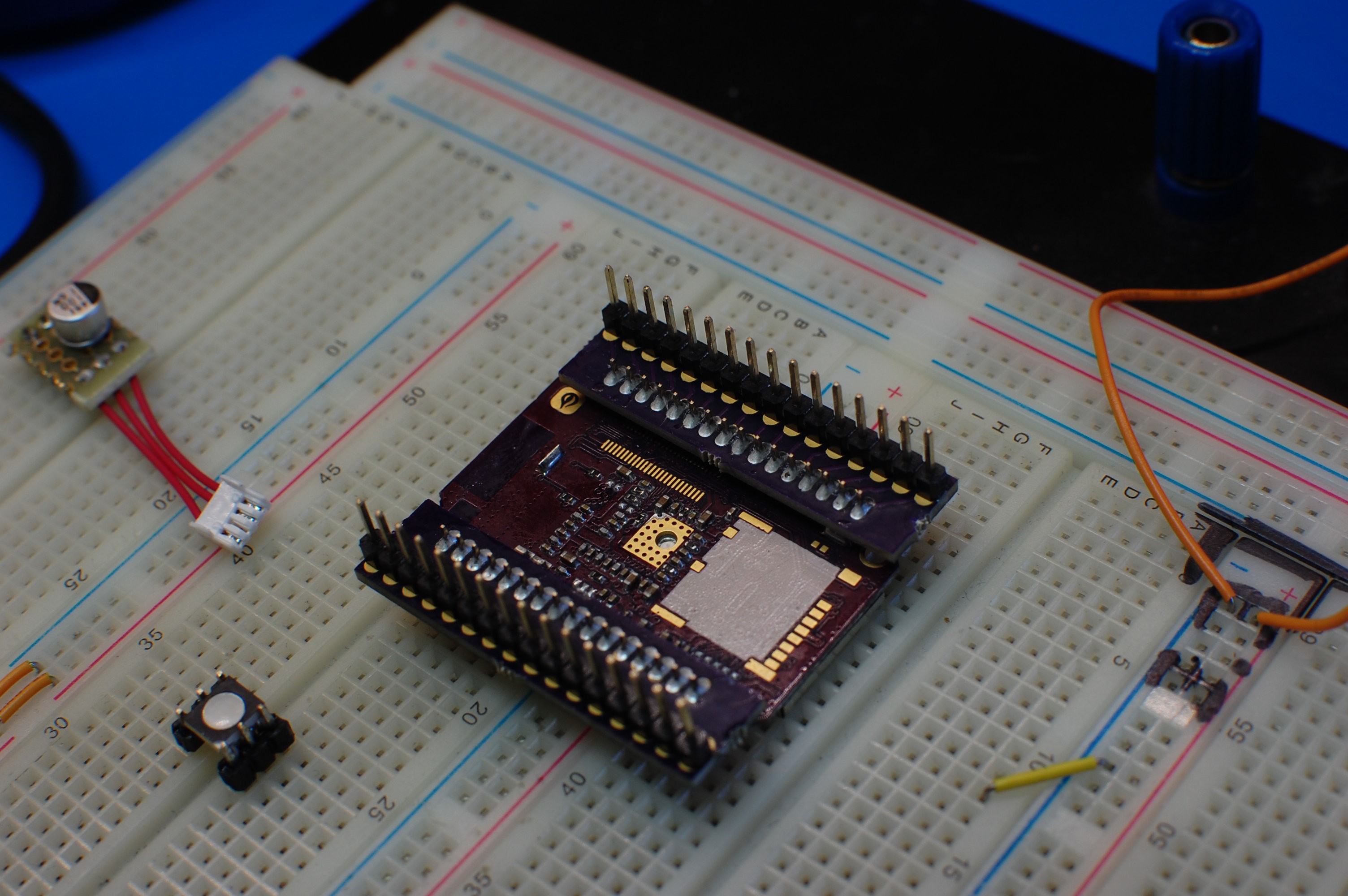
Step Three: wait two weeks, find an envelope in the mail, snap apart a header, solder 64 thru-hole joints, and be excited that you saved money:
Yes, it fits -- the board straddles half a breadboard and gives you plenty of space to pick up all 32 pins. @Onion.io: please consider changing to 0.1"/2.54mm headers like the rest of the world for your next spin, it wouldn't change the board dimensions by much and would make your product substantially more user-friendly!
I picked up a Pi Zero the other day and haven't done much with it. I should have gotten the kit, since I don't have an extra uSD card lying around and I sure as heck don't have any mini-HDMI cables. Ah well.
[photo from Adafruit]
It's a pretty nifty board, as ten billion people (give or take) have already said at this point. As I sometimes do with circuit boards when I need to procrastinate, I grabbed my loupe and gave it a close examination. A few interesting items popped out which I've attempted to image below using an exceedingly crappy 'macro' setup (F1.8/D40, 10x loupe, remote shutter release, steady hands).
The picture above shows a close-up of the space between the SD card slot (top) and the mini-HDMI port (not quite visible on the bottom). I was curious about the little flip-chip marked U8--it's a tiny 8 or 9 ball raw silicon chunk tied in with a few of the HDMI lines. The official RPi Zero schematic is only partial (it's missing the SD card and HDMI bits), but based on the RPi A/B schematic I believe this is a BAV99 high-speed switching diode array, as it seems to be connected to the same lines (HDMI_CEC_DAT, _SCL, and _SDA). However, I couldn't find a datasheet with a matching package, so that may be incorrect.
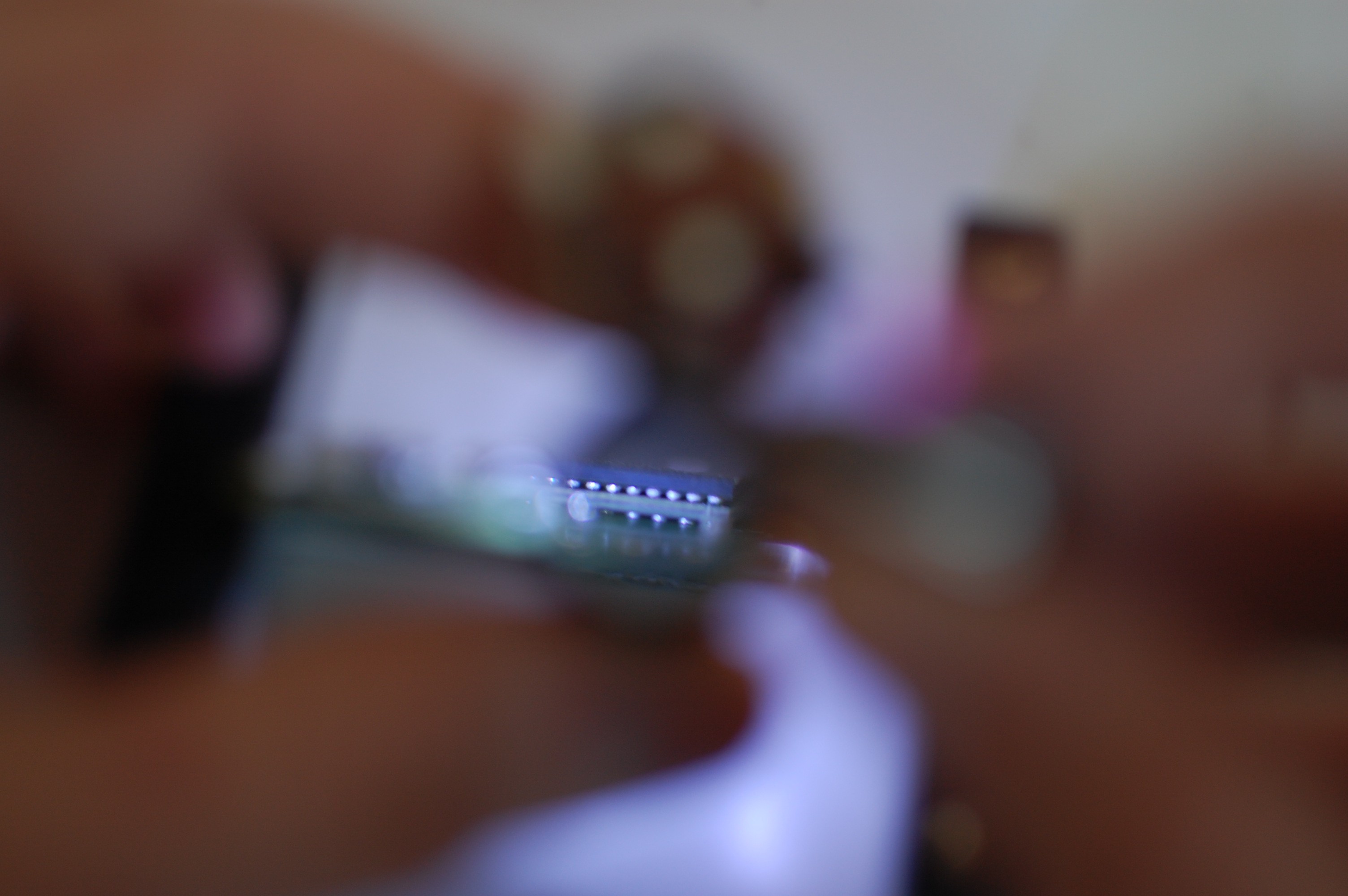
The picture above shows a close-up of the mysterious(ish) Broadcom BCM2835 SOC that runs the whole board. What was most interesting to me here is the double-stack BGA arrangement; from what I can tell, the BCM2835 rides on an FR4 plate that pretty much changes the ball pitch from ~0.4mm (guess) to ~0.65mm (another guess), presumably adding an extra row or two to make up for the decreased density or perhaps dropping a bunch of connections entirely. My theory -- the high ball density of the SOC requires a higher layer count PCB for proper escape routing, so the in-between plate allows them to use the chip with a cheaper 4 layer PCB. Anyone ever seen this before that could confirm this suspicion?
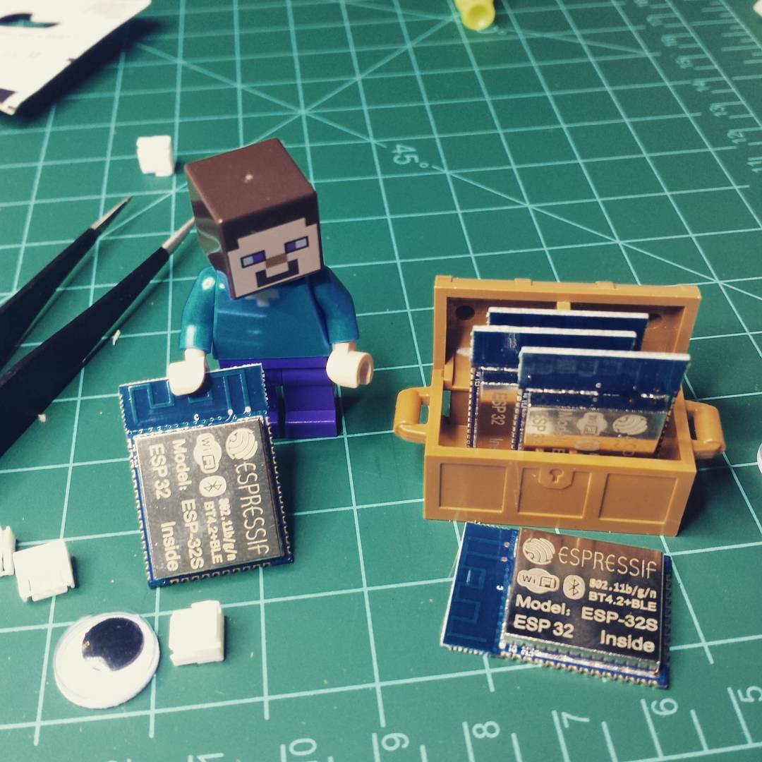
I hopped on seeed studio a few months ago and ordered a quintet of ESP32S boards. They were cheap, but didn't arrive for another 6 weeks or so:
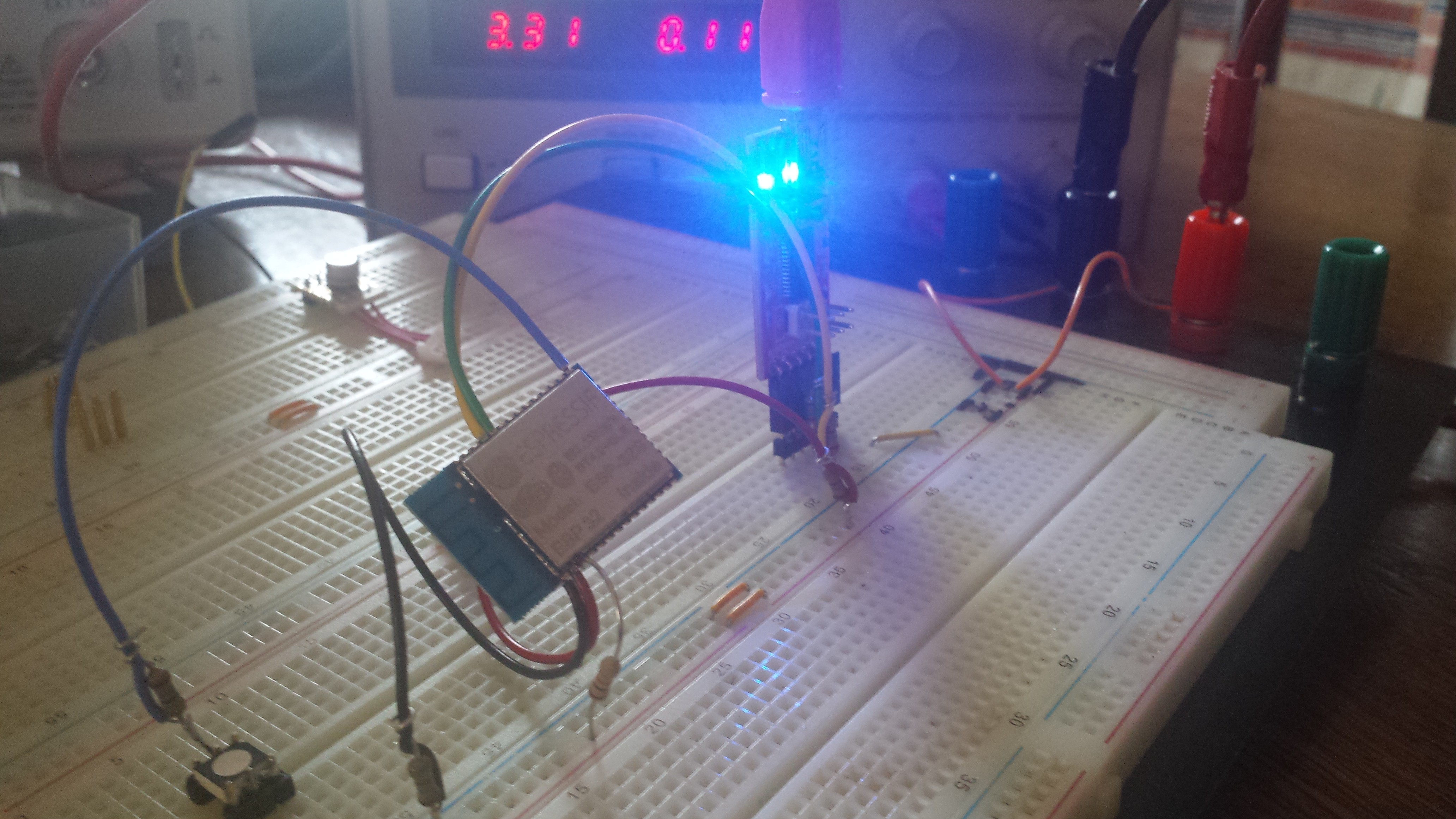
I had a bit of time between Christmas and New Years, so I finally got around to wiring a module up and running a few test programs:
Having zero experience with the platform's predecessor, getting all the bits and pieces sorted involved a steep learning curve. Fortunately, the ESP32 documentation is quite good; the list of resources at http://esp32.net/ is a great starting point, and the official forums at http://esp32.com/ are also excellent. Development and documentation of various functions seems to continue up to the minute, so it's an exciting time to have the boards in hand.
A few notes on the dev environment I've found to work well:
I run Linux Mint 17.2, so I started by following the Linux toolchain setup instructions in the ESP-IDF Github repo. Everything went pretty smoothly here.
Getting the board to flash was initially difficult; the first part of the sequence seemed to work but I kept getting header errors prior to the main program upload. Based on various bits of Internet advice, I tried:
using a benchtop 3.3VDC power supply (thinking the chip was browning out);
adding a mondo electrolytic cap to the power rails (same reason);
changing USB serial adapters (both FT232RL-based);
reversing the Tx/Rx wires a few thousand times;
mucking about with the reset and IO0 buttons (pulling IO0 low and doing a reset puts the device in program mode);
Eventually I swapped modules (hence the hastily air-soldered image above). I think I must have bricked the first one by doing something dumb with the power rails, but oddly enough it still spat out serial data. Weird.
It's pretty easy to make sure the module is working -- just fire up a serial window (I use gtkterm) with the right USB connection at 115,200 baud, reset the board, and you should see _something_ come back. If IO0 is pulled low during the reset, the terminal will tell you the module is waiting for a program.
Since getting the dev environment sorted (ish), I've gotten a few example programs to run (both of which appear to draw ~120 mA or so):
Full Wifi scan: periodically scans for all nearby Wifi access points and spits SSIDs, signal strengths, and security method into a terminal window.
Mongoose webserver: uses Mongoose to serve up a hardcoded test HTML page along with a time-since-reset counter. I modified the code slightly so the ESP32 would act as an open access point and redirect all requests to the same default page, both of which were pretty easy to do.
Neil Kolban's ongoing effort to create an easy-to-use ESP32 guide is awesome, so I highly recommend downloading his free ebook. The current revision still has a few things in progress (Mongoose WebSocket, etc) but it's quite comprehensive as is.
More to come at some point. I'd like to putz around with some of the more traditional microcontroller peripherals at some point (SPI, I2C, etc), and getting a continuous WebSocket channel open is high on the list too. Many more learnings to happen, and I still dislike programming.
I've been slacking a bit lately, but I spent some time this morning catching up--scrolling through all of the newest projects until I found a few I recognized from my last go-around. I try to do this once a week, clicking through to projects that pique my interest, leaving comments (encouragement, suggestion, etc) where appropriate, and skulling/following stuff I want to watch in the future.
Occasionally, I also check this list for stuff I missed, or projects that might have gotten more documentation at a later date: https://hackaday.io/projects/sort/updated
If you're serious about helping build a vibrant community on Hackaday.io, you should do the same. Pay it forward today and know that you'll get buckets of useful feedback when you post your own projects!
As with any other curious [/somewhat reckless] taker-aparter-of-stuff, I have a pretty solid list of unfinished projects going:
The house. It's 90 years old. It needs bathrooms, and a [better] kitchen, and a million other things. I guess this isn't really in the graveyard, but it sure can feel like it when my wife and I go for 6-month stretches without lifting a screwdriver. Prime example of the zombie nature of this project: I started restoring a set of double-hung windows over the summer of 2013. Fall hit, and I boarded them up. They're about to see a third winter with no light transmission capability (beyond unsealed gaps around the plywood panels).
The car. It's not quite as old as the house ('88), and it's a lot louder/faster/redder, but all I've really accomplished to date is (a) drive it for a few years, (b) break down a few times, (c) move it to a rented shop, and (d) tear it down into a million pieces. In that time I've gotten a few proactive (but non-DIY) things done--rust repair, machine work on the block, limited parts acquisition--but it's a lot further away from driving than it's ever been at this point. Hint: if you can drive your project to the workshop, maybe you should leave it in one piece.
#GimbalBot. I got the power supply sorted out and suddenly it's six months later. My basement hasn't been filled with the whine of brushless motors since. I sulked a bit about not getting very far in THP2k14, then found a tiny bit more energy and did a bit of work, then... hung it on the wall. Ironically, it's hung from the extra bumper of the project car.
Lots of other small projects. Things I want to reverse-engineer (like my stash of digital copier brushless motors), things I want to improve (like my Hubsan X4, which is still in pieces after the last #Hubsan X4 Replacement Frame crash), things I want to use (like the sweet radio controlled joystick belt pack I was given at work), and things I just need to re-assemble (like my spare Xbox360 controller). Or the bundle of old copper pipes from my house that I've been planning to scrap for half a decade.
I'll bet you, the unlucky HaD.io lurker that happened to find this rant, have a similar list. And you know what? That kicks ass.
Seriously, the best thing to do is to keep moving and not look back. Okay, you can look back occasionally--check to see if you've been re-inspired and want to get working again. And by all means, it's important to get rid of stuff when that's truly not going to happen--free up some cash for new projects and clear out your workspace. They're your projects; you should salvage parts whenever possible to make cool new stuff.
But don't feel bad about it, and don't let a laundry list of unfinished work put a damper on your excitement for the new and the different. The biggest letdown happens when you've finally finished something, and it works, and you absolutely are out of I/O channels or chassis capacity to add any new ridiculous features, and it's finally time to put it on the shelf or take it apart or sell it or crash it or whatever. Unfinished projects? Those are just paused journeys, waiting for you to rediscover the original inspiration that pushed you to start them in the first place.
Okay, I should really get back to work. That is all.
I engaged in some serious whiteboard tangenting last night on the subject of artificial muscles. Keep reading if you're bored as hell; this is a long-winded post.
I also took a bunch of close-up pictures, most of which ended up pretty blurry. My D40 never seems to have charged batteries and the S4 isn't the best for low-light, and the board is reflective, so... try to follow along? I've found numbering the board as I go helps me stay organized and follow along with my thought stream after the fact, so that's how I'll proceed here too.
(1) and (2): Conventions.
No close-up needed for this one. I tried to keep the physical names of items as uppercase letters and measurements (particularly angles) in Greek, but I don't think I maintained that discipline 100%. In any case, the numbers with the red circles around them designate intended read order.
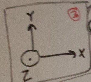
(3): Coordinates.
I made Front, Right, and Left detail drawings of the manufacturing setup; in order to speak somewhat intelligently about things like movement and rotation direction, I tried to standardize axes early:
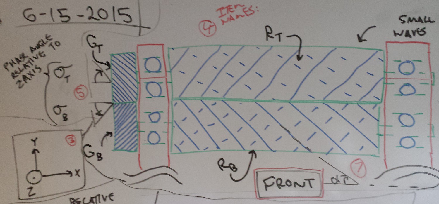
(4), (5), and (7): Front View of Stage Zero.
So what's the idea? Heated embossing and continuous fusing of flexible thermoplastics. It's not a subject I know anything about, so reading up on things like web processing, embossing, and the like will be pretty important. This drawing shows the last view a sheet of raw material sees before getting squishified:
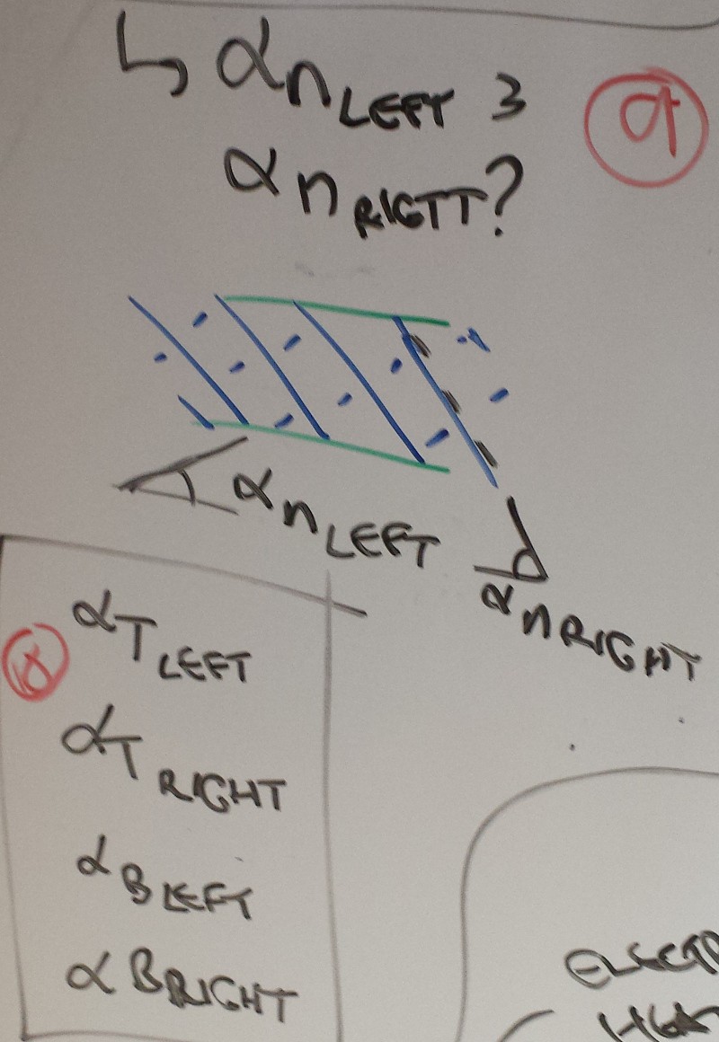
A bit of nomenclature (which I started to do in LaTeX, but that shit takes too long): R (T and B) are the top and bottom rollers; G (T and B) are the top and bottom gears; sigma (T and B) are the phase angles of the gears relative to an arbitrary line (in this case the Z-axis--this is really only used to calculate relative phase angle between the two gears); and alpha is the roller tooth pitch relative to the X axis. I spent a lot of time scratching my head and trying to figure out how to define everything parametrically, which starts using up a lot of letters really fast and gets a bit confusing.
The rollers themselves are heated, either via internal oil passageways or integral electric elements. I think one could produce passable (if quite rough) prototypes out of rapid prototyped stainless steel; I gave this a bit more thought later on and started getting concerned about raw material sticking to the rollers, so some complicated indexed lathe-based machining method might be a better choice to maintain a passable surface finish.
Roller tooth geometry--I'll get into it in more detail later. Suffice it to say that the cross hatches and lines shown in this picture aren't terribly accurate, but they're easy to draw. The rollers are mirror images of each other, rather like the two helical gears.
Boring stuff: Red bars are supports, and they have internal ball bearings. I didn't include a huge amount of detail here--they'd probably be press-fit from one side, but I think standard radial bearings will do the trick. since the axial load should be low. I might need something that can handle a high temperature, depending on the clearance between the rollers and the supports. I think some mechanism to adjust the spacing between the two shafts will be useful too--more details on that later, I suppose. I guess that would be a pain with the helical gear setup though.
TL;DR: The rollers turn in opposite directions at the same speed; they're precisely synced relative to each other, separated by a controlled phase angle; and the rollers themselves are not fully meshed (details on that too... later).
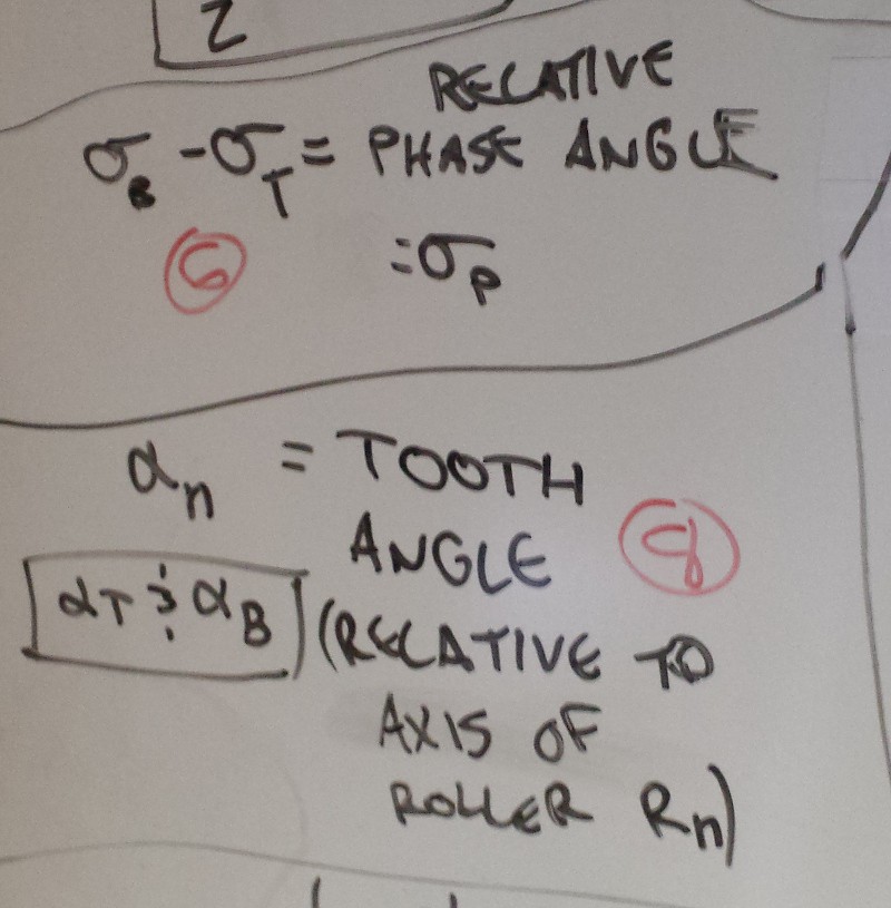
(6), (8), (9), and (10): Roller Phase and Tooth Angle.
Remember what I said about tangenting? And trying to make everything parametric? In any case, I wanted to track the pitch of each roller (alpha)... then I wanted to track the pitch of each roller twice (i.e. the teeth can be laid out in a 'rhomboidal' [alpha right == alpha left] or a 'parallelogram' [alpha right != alpha left] configuration)... then I decided to differentiate between the top and bottom...
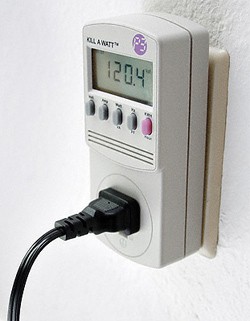
Okay, so pretend you aren't a hacker. You don't care about the latest in home automation, you don't know a volt from an amp, and you think it's okay to use that crappy 16-gauge 6' extension cord with a 1500W space heater. But you DO care about your power bill and you want to see how much your appliances are costing you, so you buy one of these at your local big-box home improvement store:
What makes the Kill-A-Watt so successful?
To start with, the name is a great pun that helps users link their electric bills (measured in kilowatts) with the actual power draw of a typical appliance (probably in the tens or hundreds of watts). This might sound simple, but I think it makes the product a heck of a lot more accessible to a broad range of consumers. Better, reducing your power bill is all about 'killing watts'--perfect!
More importantly, the meter is dead simple to use. Plug it in line with your appliances, plug it into the wall, turn it on, and BAM! Real-time power consumption information. I should confess that I don't own a Kill-A-Watt (and haven't used one), but I'm guessing they have some other basic diagnostic functions on board too--maybe a datalogger that measures total watt-hours along with instantaneous readings. But all of this would be worthless if you had to hire an electrician to install it! The Kill-A-Watt shines because it reduces a complex subject (energy efficiency improvement via increased data visibility and habit change) to a simple game (look, a big number! that means money. make the big number smaller!).
Water is the next frontier. Not natural gas--it's cheap now, but if/when it gets substantially more expensive we've already got a decent infrastructure to switch over to electric heating appliances. Water, on the other hand, is a renewable but finite natural resource. It's already getting much more expensive, and the current drought in the western US is putting a massive strain on our current usage habits. Regulations have evolved in an attempt to reduce personal consumption rates, but 20-minute showers (something I'm sometimes guilty of taking) will only really stop when we understand how much they cost. It's worth stating here that the majority of water use in the US is taken up by agriculture; even so, it's something we all need to take seriously.
So why don't we have point-of-use metering? The Kill-A-Watt fills the gap between a home's power meter (which nowadays can be pretty sophisticated) and each individual device. In other words, you can meter the power consumption of your TV while it's off without having to shut down every other electrical device in the house to get a realistic reading. However, point-of-use water meters, as far as I know, really aren't a thing. The devices most people are familiar with are mechanical turbine meters that need to be plumbed in permanently--not an issue for a plumber or a handy homeowner (although they might violate local code depending on the device), but definitely a barrier to adoption for the typical user. It would be like replacing individual receptacles with flush-mount Kill-A-Watt meters: not practical at all.
I spent four years selling process instrumentation to a variety industries in greater Minnesota. In comparing this work with my exposure to the hobby world, I've always been struck by the massive technological gap that exists between DIY-grade sensors and industrial instruments. I'm not just talking about durability and size; sure, industry does have access to big expensive mechanical flow meters:
... but that's not really the point. When I was on the road, I never sold mechanical flow meters. Okay, I had a few customers that wanted to hold on to legacy equipment, or had very specific reasons for preferring a device with moving parts, but these examples were the exception to the rule across a wide range of industries and applications. Instead, we used superior technologies. Gas flow measurement? Thermal dispersion. Conductive liquid? Electromagnetic (and no, not...
I have my viewpoints on the subject, but I'd like to hear others. What are the pros and cons of protecting a project's intellectual property? When does it make sense to do one or the other, and can a hybrid still be considered "open"? Will keeping a hardware project completely open source ultimately doom it to commoditization?
I have been mulling this question over a bit in my head lately; I tried putting a post together on my phone late last night, but the numbered list function didn't seem to play nicely with Android/Firefox. Oh well, more time to sleep on it I suppose.
This all started when I realized that I tend to toss up project logs a bit more --ahem-- liberally than some fellow HaD.io users. There isn't currently a 'sort by number of project logs' option in the project view, but I'm guessing GimbalBot would slide in near the top of the list with a concerning 70 entries (and counting). I should start by saying that I don't think this is necessarily something I should be proud of; if sharing valuable information is one of the goals of this site, then over-documentation is just as bad as under-documentation if the added bits aren't important.
In any case, I've been running a thoroughly non-scientific survey in the back of my mind over the last year, trying to categorize the different use cases for HaD.io. A few that seem to pop up with some frequency:
Blogging/Lab Notebook. Updates to projects aren't necessarily related to milestones; rather, they are summaries of a given period of working, such as a weekend or an evening of tinkering. I do this a ton; I'm guessing it can get a bit annoying for the folks that follow me.
Finished Project Sharing. Might or might not be unique (the latter often indicated with something like "this has been done many times before, but here is my take..."). Usually marked Completed Project, or at least to the point of either (a) open-sourcing the whole thing and encouraging people to replicate and verify, or (b) trying to launch a Kickstarter or go after mass production. Or (c), throwing the project on the shelf so it can collect a bit of dust before being repurposed down the road.
Feedback and Discussion. Asking for or providing suggestions for a design, sometimes (but not always) explicitly. I think we should always strive to encourage this type of discourse most of all, since we all bring a unique perspective to the table. We can always use more positive criticism/feedback.
Placeholders. This post is sort of a placeholder, since it's far from being a finished thought. A lot of folks add projects that are placeholders--they don't have much content beyond a sentence or two and maybe a picture, and they might revisit the post in months or years. I'm doing this with my Rangemaster project; it's still something I want to do, but I'm waiting for the time to be right. I guess.
What else? How do you use HaD.io? How should we use the site? I love (1) because it gives me a running log of what I've done on a project, but is that the right way to use the site?
I'm not sure this is something I want to pursue right now, but I stumbled upon a Reddit comment from [Mike Szczys] some time ago that stuck with me. He brings up a great point regarding utilitarian IoT devices; as an early purchaser and rapid abandon-er of a Fitbit, I'm definitely interested in cheap, connected sensors that have real value.
He used the example of the mandated CO/smoke detector--why didn't it send notifications to one's smartphone?
I started thinking about how I could get around this. Build a smoke/CO detector? Probably doable, provided I could find the parts. It would probably be easiest to use a reference circuit from the various sensor datasheets, assuming that sort of thing exists--maybe the First Alert company (and others) actually manufacture and own the supply chain for their sensors. Who knows?
I think a better approach could be to bypass the alarm guys entirely. Not that there isn't room for a product like that; last time I bought a combo detector I think it was in the neighborhood of $50, give or take. Seems like these units often come with other fancy features (like the dude that yells, "Fire, Fire, Fire" whenever I cook steaks), so maybe there is enough room in the budget to throw in an ESP8266 or something. But then you'd need to worry about the safety side of things--it's a smoke/CO alarm, and your life really does depend on it working reliably. At the very least, you'd want to install an unmodified factory original unless you somehow got the project through certification.
What about an ESP8266, a suitable microcontroller (or itself--from what I understand, folks have figured out how to program them), a microphone, and maybe a dedicated A/D chip? Or an analog bandpass filter, tuned to the audio frequency of a typical fire alarm? Put the system in some type of 'training' mode when it's near the alarm and trigger a smoke alarm test. Could a Trinket Pro handle the A/D part natively to minimize size and board count?
I don't want to spread myself too thin. I just picked a project up that I'd set aside for another project, which I've now set aside. But the Trinket Pro contest could be fun.

 Above: a $5 Linux computer that uses 2mm header pins, meaning it requires a $10 - $15 dock to use.
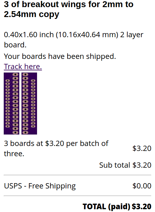
 [photo from Adafruit]
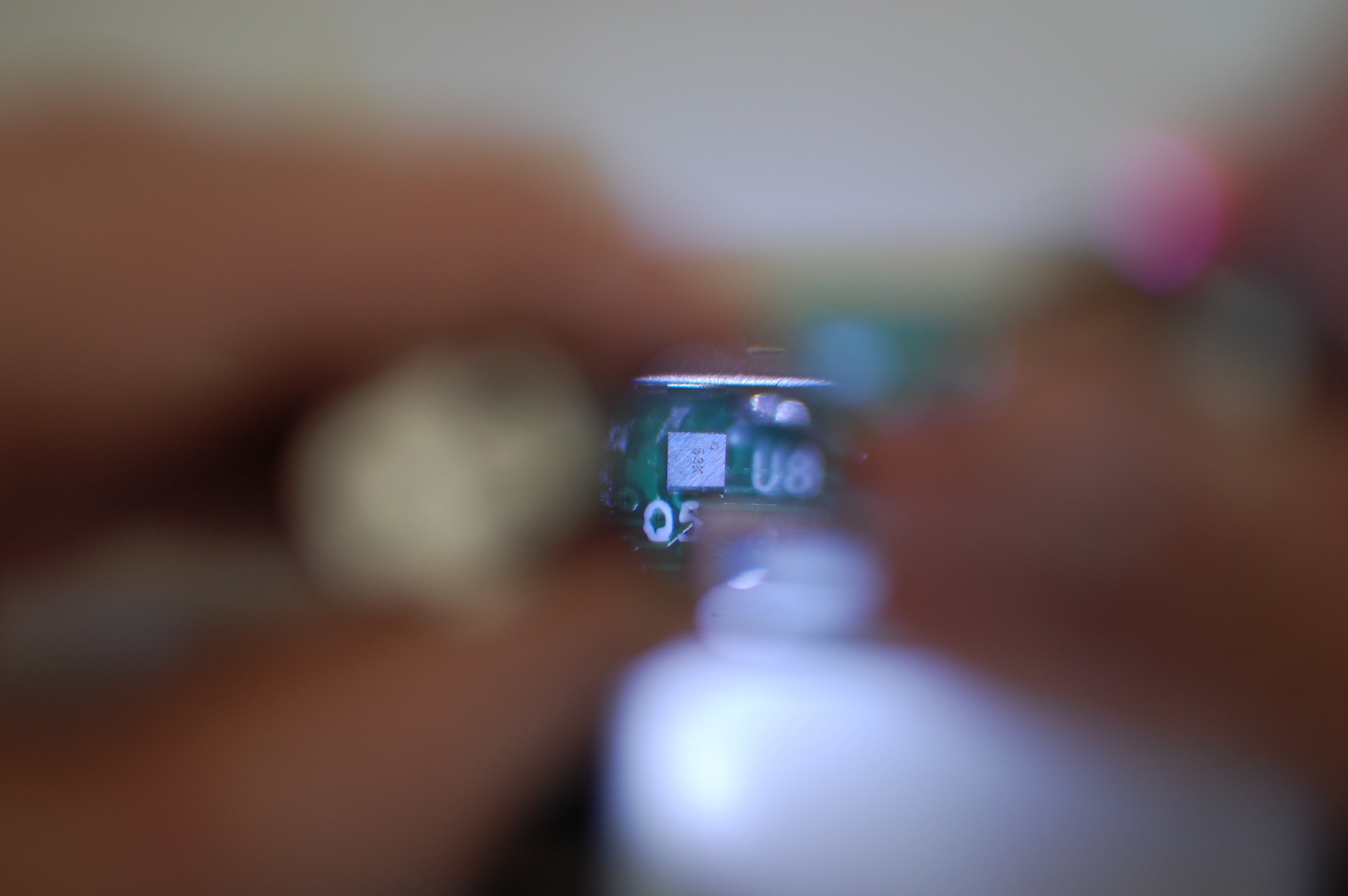
 Having zero experience with the platform's predecessor, getting all the bits and pieces sorted involved a steep learning curve. Fortunately, the ESP32 documentation is quite good; the list of resources at http://esp32.net/ is a great starting point, and the official forums at http://esp32.com/ are also excellent. Development and documentation of various functions seems to continue up to the minute, so it's an exciting time to have the boards in hand.
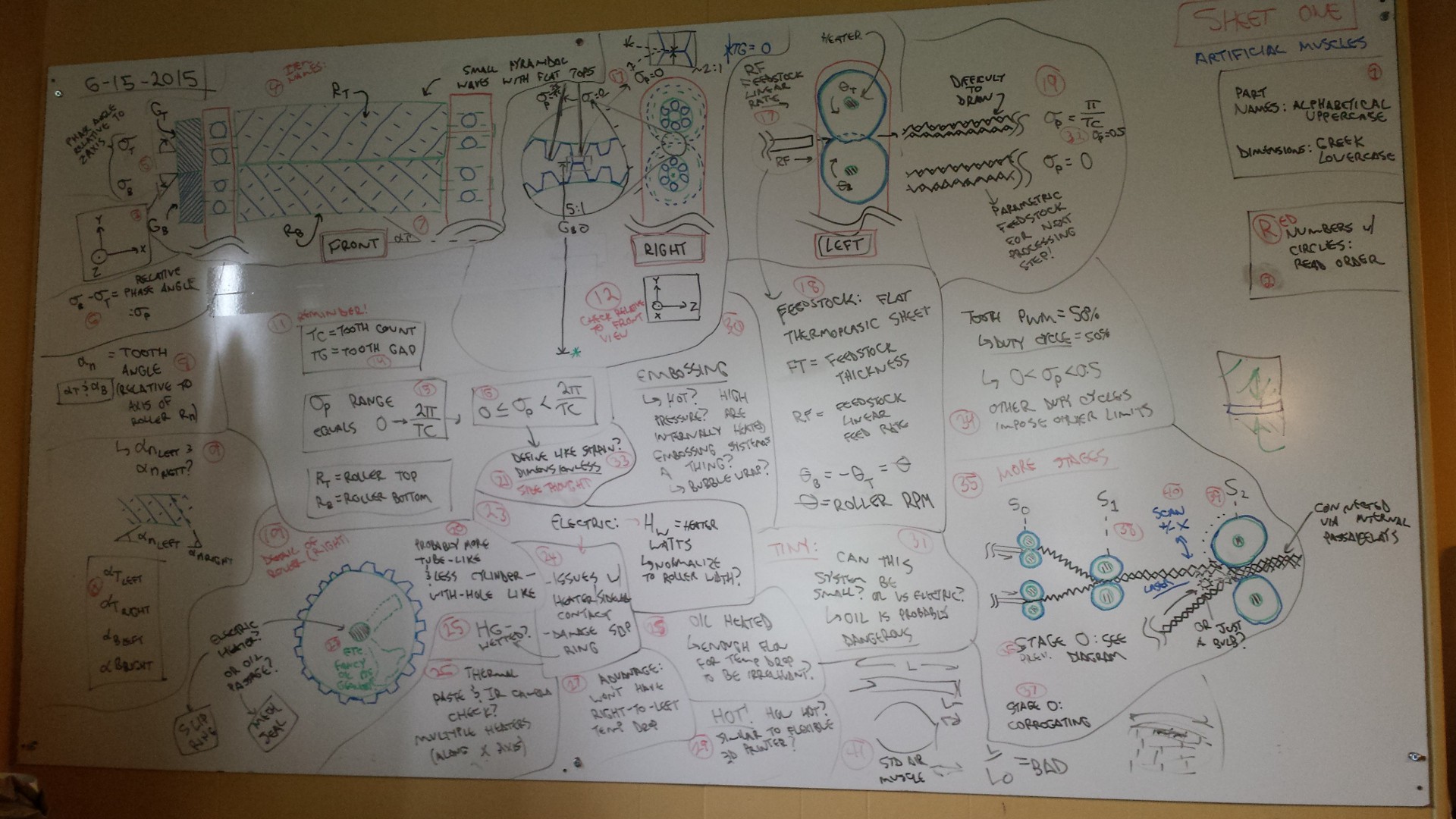


 Not a great diagram but hopefully you get the idea. The wood base has several layers, and you have to imagine that the leftmost layer extends out towards the viewer along the dashed line. That way, when a wedge is inserted into the rectangular 'wedge goes here' slot, it pushes the upper bit of the connector plate to the left as its driven into place, clamping the board securely in place. I really should reference a side view or 3D model with this sectional image, but... here we are.
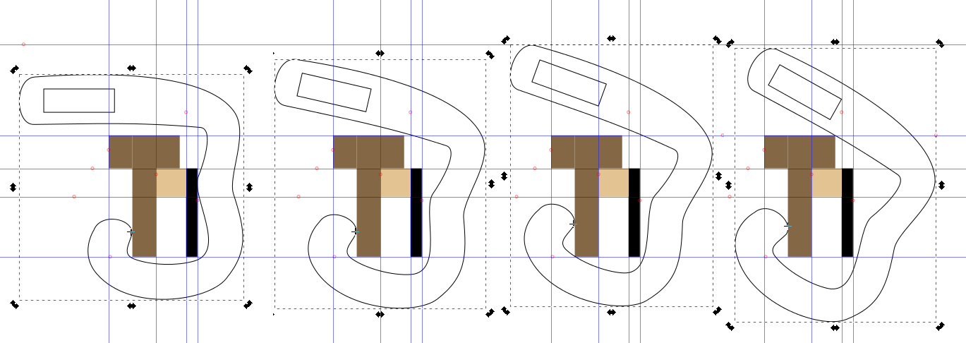 Note that in the third frame, I actually translated the connector plate up a bit so one of the corners can clear. This is much easier during real life assembly; you really just need to be sure everything clears at all points during the rotation/translation, as manual assembly makes combining both movements quite intuitive.