-
LibreSOC and TinyTapeout pictures @FSiC2024
06/23/2024 at 01:36 • 6 commentsWe talk a lot about architectures and semiconductors.
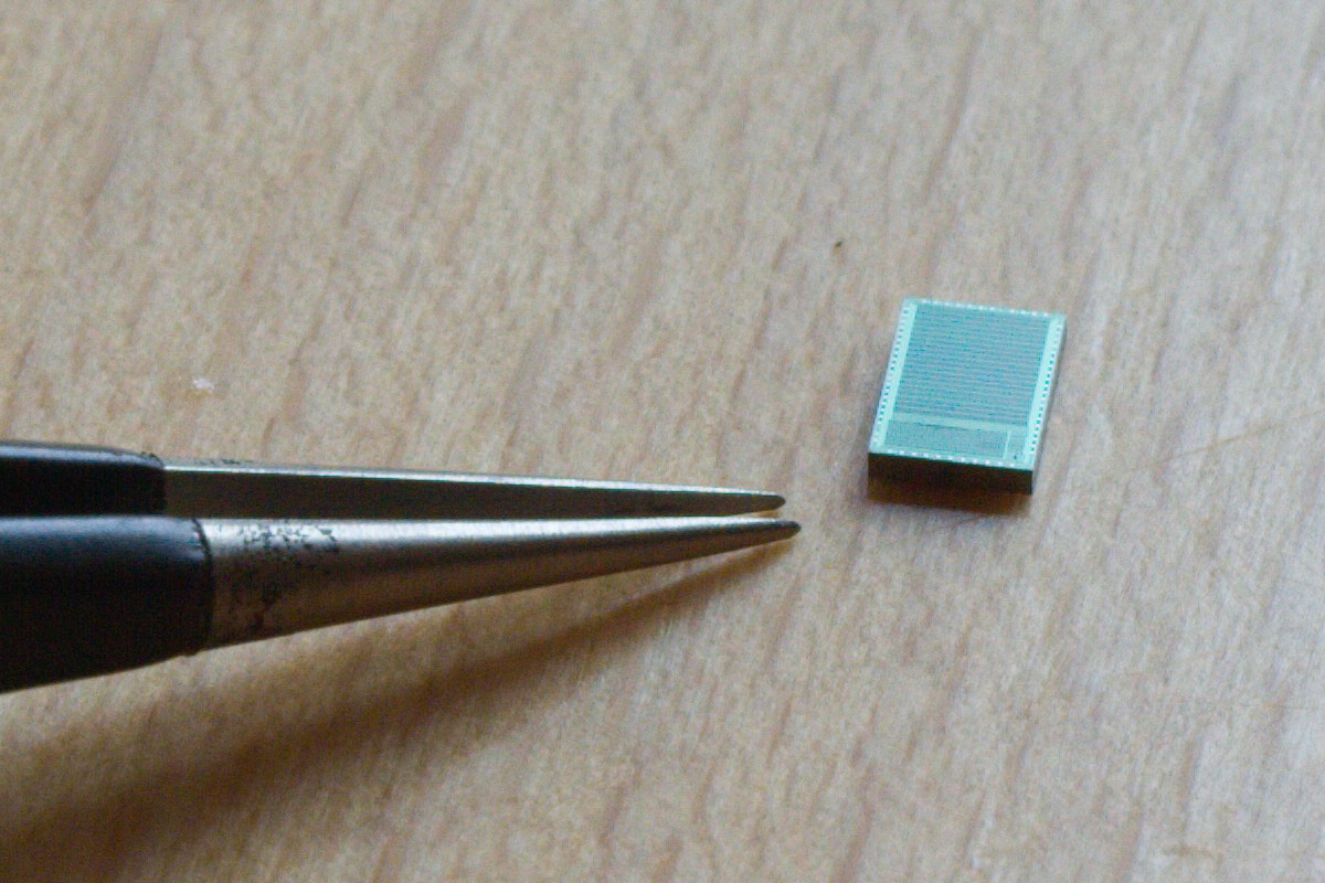
At the FSiC2024 conference in Paris, I saw real integrated circuits and took pictures, including TinyTapeout chips and the LibreSOC samples/prototypes.
I have uploaded some of them on Wikipedia to contribute to the Libre-SOC page.
![]()
![]()
![]()
And here Thorsten showing some TT samples in bare die and QFN package.
And one board demonstrated by @matt venn !
.
-
More operator symbols
11/24/2023 at 14:51 • 0 commentsTo say that I am frustrated by the vocabulary of some common languages is an understatement. JavaScript introduced the ">>>" symbol for the arithmetic (sign-preserving) shift but we're still far from satisfaction.
The Pascal family of languages don't bother with such details because operators use all-letters operators : sll, shl... But the C-like syntax is preferred today so I need to be creative.
Carry-related operations are traditionally absent, which is a shame. So let's skip directly to the rotations : there is no direct symbol for this, but I have long wanted to modify the shift symbols:
<<@  rotate left

>>@  rotate right
Or maybe a shorter version:
<@  rotate left

@>  rotate right
which is less effort than having to analyse the syntax tree and look for a compound operation (OR of two SHIFTs with the same arguments and the shift amounts sum up to 32 or 64).
Now there is an even trickier symbol to choose : I need UMIN, UMAX, SMIN and SMAX (unsigned and signed minimum and maximum) The < and > symbols will be used but how to discern between signed and non signed operations ?
<? MIN

?> MAX
The Dollar symbol looks like a S so
<$ SMIN

$> SMAX
could do the trick.
Any advice or prior art is welcome !
-
Addendum ABCE
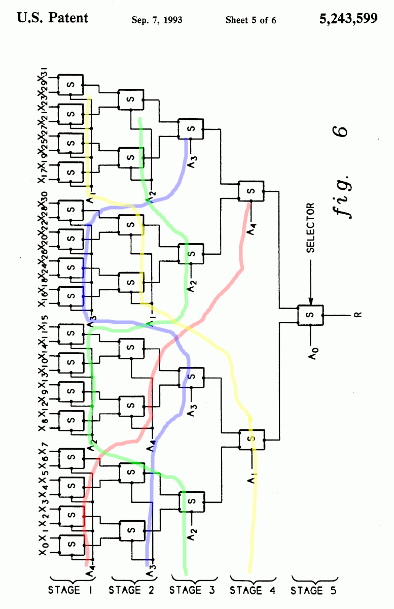
09/26/2023 at 06:43 • 0 commentsI have covered permutations of control signals in binary trees many years ago, I have even published 2 articles:
And I recently became aware that I am only a rediscoverer, as there are 2 patents:
https://patents.google.com/patent/US5243599A/en by IBM, expired in 2011
"Tree-type multiplexers and methods for configuring the same"
Figure 6 is clearly a balanced tree (32 leaves, 1,7,7,8,8 configuration)
![]()
https://patents.google.com/patent/US20120194250 AMD, seems identical but expires in 2031 ???
I have not been able to understand the difference between the two patents but this would explain why the technique has not appeared on my radar before : who wants to walk on IBM's toes ? However its validity is gone since a dozen years now so why restrain ourselves ?
Addendum to the addendum :
https://arxiv.org/abs/2405.16938
https://arxiv.org/abs/2405.16968
The subject is still alive !
-
strings in C
05/06/2023 at 03:58 • 4 commentsI'm 46 years old and only now do I realize that there is <strings.h> and <string.h>
WTF.
-
I don't make projects.
08/25/2022 at 16:46 • 0 commentsProjects make me...
-
The Sorting Demon
08/13/2022 at 16:07 • 0 commentsI must have watched too many videos of graphical sorting algorithm visualisations. These are hypnotic... I'm so impressed by radix sort and bucket sort, and all the others have a very good lesson in algorithmics to give. But there is always this voice in your head that says, without telling how or why, that "there must be a better way" for simpler situations, which explains why there are so many sorting algorithms out there, and sorting is used in many places so why resist...
I was looking at the Fibonacci Heap algorithm and wondered how it could be turned into a sorting algorithm, so... nah. I want something much simpler. And it seems I have devised something that borrows from many domains. It is probably not the best (radix sort being the best ever, yeah) but "at least it's mine and i know how to do it" (a variant on the NIH syndrome). It may already exist under a name I don't know, but do I care ?
It is based around the merge sort principle, which I love due to its simplicity, but I want it to work well both on totally random and on sorted inputs. So it has 2 stages :
- First : scan the incoming sequence for an ascending, then a descending sequence. Once they are identified/tagged, a merge sort can be applied to obtain one ascending sequence, by scanning the descending sequence backwards.
- Second : merge sort all of the "rectified" sequences. But this is where it gets less trivial. The issue is that merge sorting works best when the inputs have a similar length. So the order of merging would be... ideally determined by a modified Huffman tree ? A simpler version would use avalanches or something like that...
The last part has all the "smarts" because the first part is pretty easy. The Huffman approach may be overkill but the idea of "avalanche" sounds great and applies an adaptive binary approach naturally, while allowing in-place operation with the help of a reasonably-sized stack.
The merge algorithm is under-utilised if the 2 input sequences have a length ratio of about 2 (approximately) so this should be avoided. The only way to be sure that a new sequence is at least as large as the current sequence is if the new sequence is larger, and then check/iterate again... an avalanche...
The algorithm would alternate between the 2 stages :
- scan the input for ascending and descending extents (complexity : N comparisons), then merge them (N comparisons and N moves).
- see if the size of the current extent is larger than the previously available in memory. If yes, merge them. Loop to 2.
I'm sure I'm reinventing something here... but some other details must be somewhat new :-P
Now, there is something to be aware of : if a sequence is perfectly scrambled/shuffled with a random permutation, half of the sequences are 1-datum long, one quarter has 2 numbers, one eighth is 3 data long... So a pre-filter already does a LOT of work.
Anyway, with the first scan part, the algo works ideally if the input is already sorted in both ascending and descending, and the 2nd part does the rest...
I should try to code it !
...
Well OK I'm coding it.
...
20220815 : hmmm'ok, it looks like it's a cousin of Timsort. Except I don't bother with insertion sort or even a minimal size of the merge sort. The "cascade" condition of merge ensures there is no stack problem.
-
Going (mostly) Software
05/20/2022 at 18:07 • 0 commentsThere was a time, 15 years ago, when the € was "strong" and I would buy tons of surplus parts on eBay. That was the great, glorious time, I'd say, and things only got worse from there.
It eroded slowly, over a long period : the USD regained its power so importing or trading in € would become less and less worth it. But still, the world was moving "online" and we could find more and more unobtainium so it was OK.
Two more things degraded : first, delivery became more and more of a hassle. The "last mile" link, the person meant to ring on your doorbell, was more and more unwilling to make that effort. So a lot of back and forth with the shipping companies or the state-owned service. Yeah, work conditions are harsh but we could feel the will was not there.
And the onlinisation of electronics parts distribution became extreme: a bookseller would trade electronic parts or assemblies from shady Chinese "brands". If I wanted shady, I'd hit the "first price tier" on eBay, be very patient and have cheap delivery. But Amazon promoted the dirt cheap products (with expected quality issues) to a desirable item and this trend has been amplified in the last half decade. It is not a benefit to the consumer because the supply chain is not so different from ali baba or eBay or others, but a premium price is slapped on top of it.
Oh and import duties became "enforced" more stringently. Affordable US parts became less desirable in Europe, and this shifted more customers to China for the dirt cheap parts. The flow of great goods from USA stalled. Today I don't even consider looking across the Atlantic to source anything but the most specific, direly required tool.
Anyway more and more parts are available online, which is great for us tinkerers. Professional/enterprise-only stores would slowly open to us, mere mortals: Farnell has managed to ride that wave when it felt that the Raspberry Pi crowd could help boost its bottom line and attract new customers who would be delighted to access high quality parts and references they couldn't imagine existed.
But slowly the frenzy died with the new normalisation, the binge turned into a careful sip. Hackaday projects overall are less exuberant, right?
And then Trump came and started an economic war with China. What could go wrong?! I ordered little from China and failed deliveries became significant.
And then COVID came. The tense situation totally snapped. The industry is totally belly up. I ordered a sweet PolarFire FPGA kit in oct. 2021 and the delivery has been postponed again and again. And then again.
Today's lead time for this kit is 43 days (as of 20220520) but the last notice I received announced July 2023. Can you wait 2 years for one devkit ? And I am not even bothered that the 4× RPi3 I ordered have been cancelled right away without notice. And last time I wanted to order 2N2369s for the #Logic strips, the Chinese reseller flaked (due to stock mismanagement, we will say). Ordering Arduino Nanos from Spain ? Forget it. Getting an affordable lot of Pi (for the #Clunky McCluster ) is not reasonable, so it's shelved too.
Prices have gone way up, availability is down, the free flow of money and goods is breaking down. The time for playing is over.
Sure, some orders still go through. But then Vlad decided to go kamikaze and at least the Eastern Europe is now out of reach, which is very sad because the old Red Army surplus parts were cheap, funky and abundant.
Instead now it's a global economic war.
This whole downward situation is tragic in many ways but at least I have ample stock of stuff for mundane stuff. I have stockpiled insane amount of certain parts. Maybe I could earn a bit of pocket money by selling some of it but I'm a hoarder and I would feel I'm the loser, not the speculator.
So this explains the title: in order to stay creative, I'm back to pure algo, coding, programming, virtual design. It's safe, "mostly free" as long as I have a stable Linux+electricity+Internet. It's sad...
Read more -
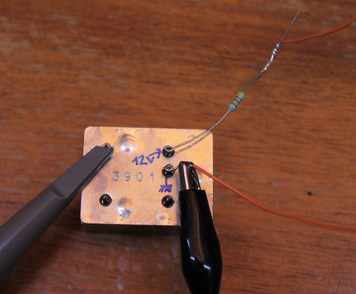
Weird Hall effect sensor anomaly : outputs 12V !
04/08/2022 at 23:26 • 0 commentsI didn't dream and I made a video to prove it so this is not an April fool's joke.
It could have been a fluke but recently another HES pulled that trick on me so I had to post this and ask you all guys : WHY ?
The most logical explanation would be a step-up charge pump for internal bias but then WHY would that voltage appear on the output pin ?
Are there reports of weird voltages in the wild ?
This can be very dangerous, for example if the pin is directly tied to a Raspberry Pi GPIO...
-
Resistance is fut^Wavailable
03/31/2022 at 21:47 • 7 commentsYou're never safe from a good surprise !
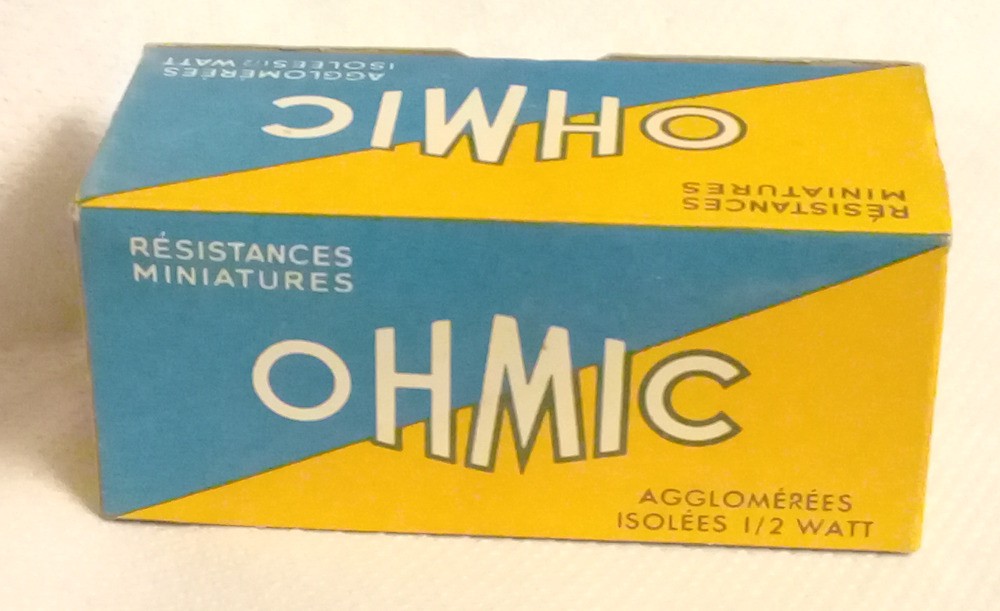
A renowned electronic parts store in Paris (one of the too few remaining) found an old box in the back of their warehouse and sold its contents for such a ridiculous price that I bought the whole box. I happened to visit the store at the right time, and left so crazy happy...
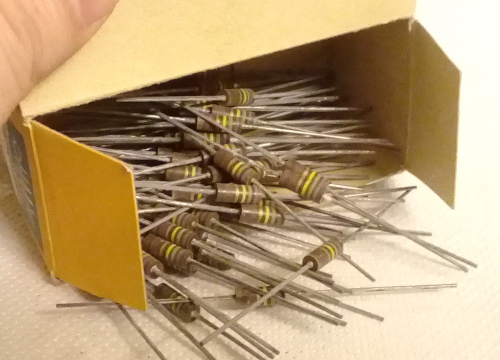
![]()
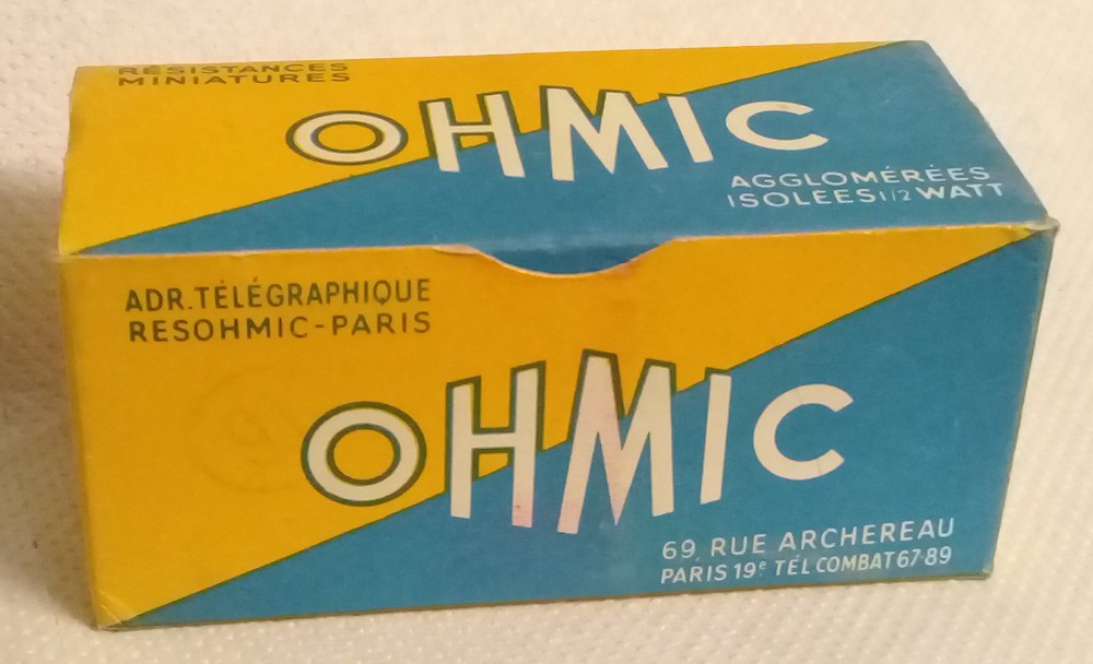
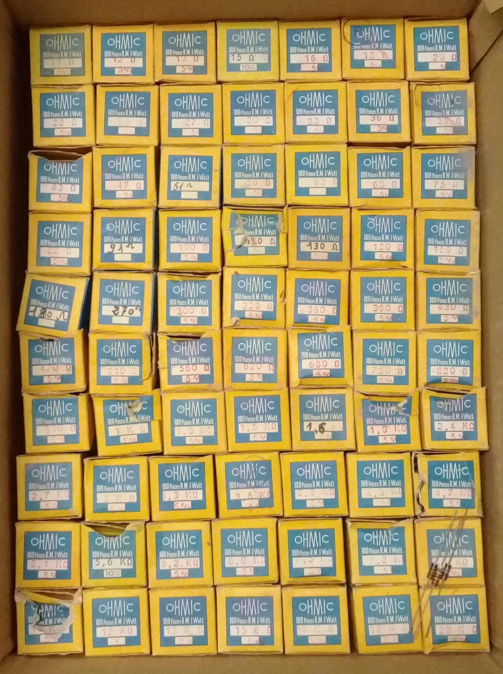
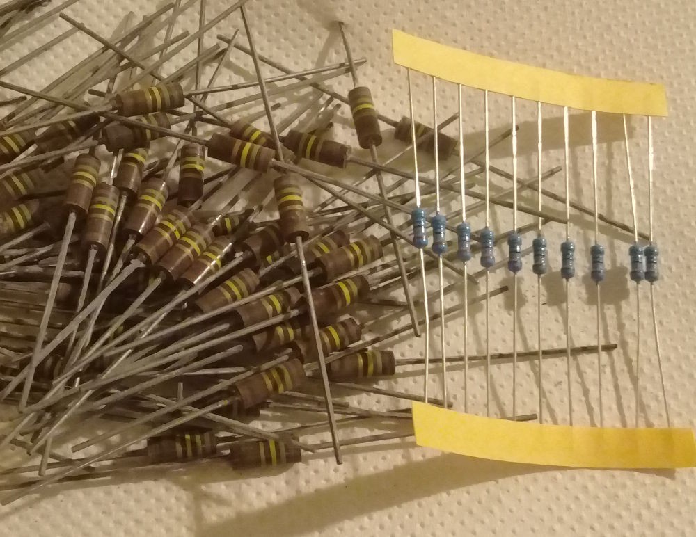
These are boxes of vintage 5% 1/2W (approx. 50pc) and 2W (approx. 5pc) resistors, of the OHMIC brand (never heard of it). Type is "agglomerated". Made in France !
![]()
I have no idea of the date codes but the packages are mostly intact. How old is it ? I have no idea, but the phone number on the package looks like some 1950s or 1960s at best. So it might be 50 years old easily.
The address of the company is approx. 3km from my place though now the building is a sort of high school.
Some boxes have been opened and parts added or removed (probably from other boxes or existing stock)
![]()
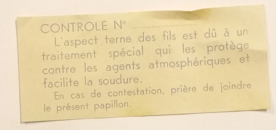
The leads look very oxidised but it might be some sort of flux or whatever, according to the small sheet/notice inside one box. I'll have to investigate.
![]()
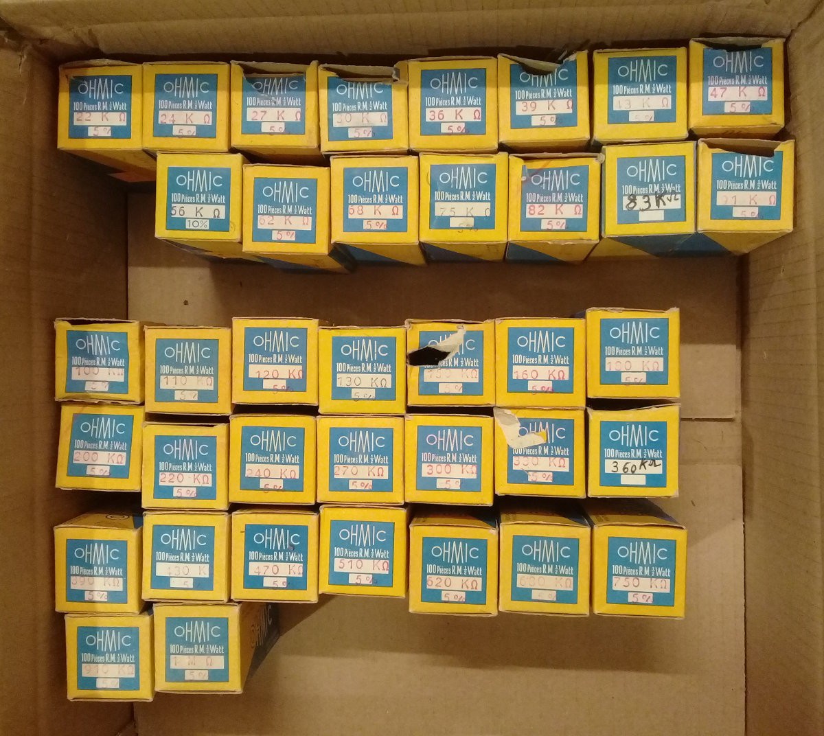
This is totally insane ! We're speaking of the stock of a store, with radically vintage parts. It was a total steal, the deal of the year ! And even better than that : the range of values is exhaustive. Like close to E24 ! Thus, due to the variations, I can pick from neighbouring boxes if one value is exhausted.
This means that most of my needs for resistors in my neovintage projects are met. They look RAD.
![]()
![]()
So here I make a little inventory...
×10
11, 12, 13, 15, 16, 18, 20, 22, 24, 27, 30, 33, 36, 39, 43, 47, 51, 56, 62, 68, 75, 82, 91
×100
100, 120, 130, 150, 160, 180, 270, 300, 330, 360, 390, 430, 470, 510, 560, 620, 680, 750, 820, 910
×1K
1K, 1.3K, 1.5K, 1.6K, 1.8K, 2.4K, 2.7K, 3K, 3.3K, 3.6K, 3.9K, 4.3K, 4.7K, 5.1K, 5.6K, 6.2K, 6.8K, 7.5K, 8.2K, 9.1K
×10K
10K, 12K, 13K, 15K, 16K, 18K, 20K, 22K, 24K, 27K, 30K, 36K, 39K, 43K, 47K, 56K, 62K, 68K, 75K, 82K, 83K , 91K
×100K
100K, 110K, 120K, 130K, 160K, 180K, 200K, 220K, 240K, 270K, 300K, 330K, 360K, 390K, 430K, 470K, 510K, 620K, 680K, 750K, 910K
×1M
1M
.
The look is one thing, the value however is what matters from the electronics perspective. These are sold as 5% but I measured values that are 10% off... Humidity and other ageing factors certainly have affected the reliability and accuracy, I'll probably have to "bin" the parts and avoid using them at full power rating. This should be "good enough" for digital electronics though.
The actual quantity varies from box to box, certainly depending on the orders, sales and requirements. The crazy low price might also be because these parts would blink red alert signals on a RoHS checklist. Don't lick your fingers after manipulating them !!!
Look how far we have evolved in 60 years: a 1/2W resistor vs a 1/4 chinese modern hypercheap resistor...
![]()
Would I be willing to sell some of them ? Maybe, though I do not feel comfortable with it, even though it could be easy money, so maybe I'd accept some parts swap, unless another type of deal is possible. But with the international situation right now, I would rather keep the boxes well sheltered. It'd be a shame if something happened to this collection.
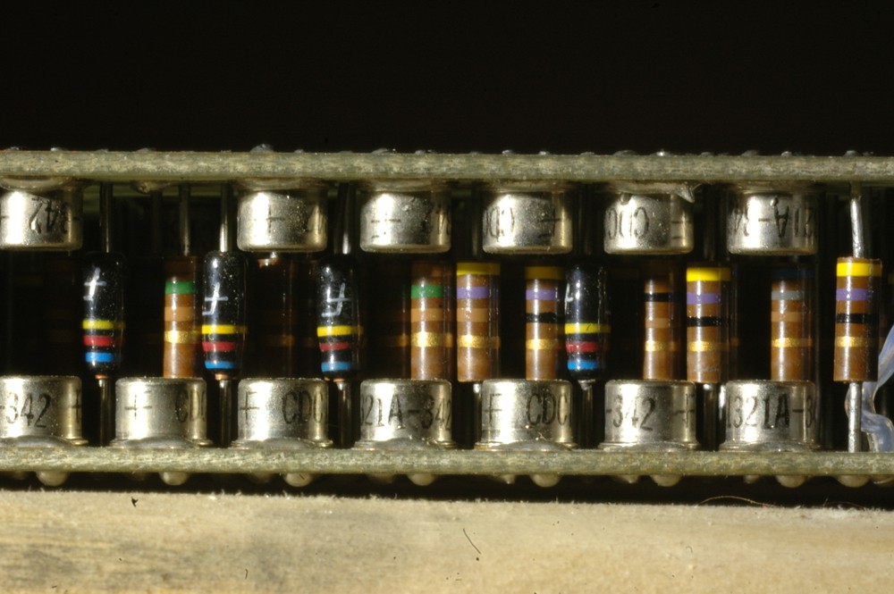
Edit: @sxpert notices that this is the same type as used in the CDC6600.
![Resistors in a CDC 6600 module Resistors in a CDC 6600 module]()
Resistors in a CDC 6600 module This is the same type because it was common at the time, I believe that Bourns still offers them and the Soviets built them too (I bought "some" on eBay for my neovintage projects). Either OHMIC manufactured them under licence, imported them or used expired patents. It should also be noted that the French electronics industry was budding after WW2, as witnessed by the discovery of the bipolar transistor effect mere months after Bell Labs. Like other industries in Germany, Italy and Great Britain, it crumbled under the combined pressures of political uncertainty, market efficiency and economy of scale....
Read more -
Diode full bridge as freewheel
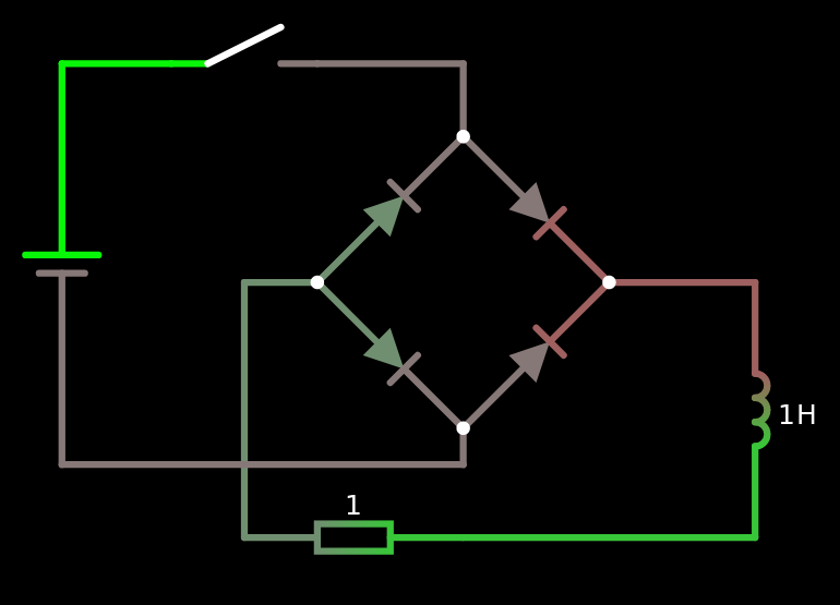
09/02/2021 at 21:43 • 0 commentsOK let's say I have a solenoid powered by an undetermined power supply (I don't bother measuring the polarity). And a solenoid requires a freewheel diode but the diode's polarity should be adapted to the polarity, which I don't want to care about. Naturally, a diode bridge comes to mind but will that work as a freewheel diode ? Apparently yes according to CircuiJS :-)
![]()
And now that I see the currents and voltages, it becomes obvious that it would work. The good thing is that the EMF back-kick power is shared among the 4 diodes and the drop is doubled, meaning faster dissipation and less stress/more reliability for the diodes. How nice ! -
Right to repair and historical perspective
07/30/2021 at 04:58 • 0 commentsThank you Steve !
I mean, the other Steve ;-)
At least, one of the Apple founders lives in reality ;-)
-
What's a "typical relay" ?
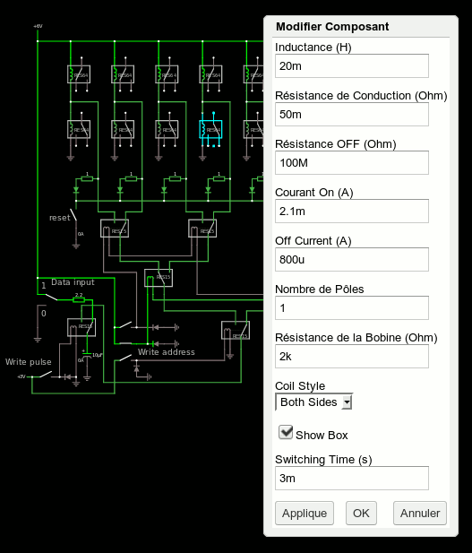
06/29/2021 at 23:41 • 0 commentsWhile discussing with Paul Falstad about a new feature of circuitjs, came the question of which default parameter to propose to the users.
![]()
For basic simulations, the contact's resistances can be pushed to the limits (on: 1m Ohm - off: 1G Ohm) because this does not affect the results much. Beware however because you'll get nanoamperes of leakage here and there.
I like how you can configure the number of poles, the position of the coil, the appearance of the box, but there are more critical parameters. And we're back to the question: "what is a typical relay ?" There are so many types, sorts, models, brands, uses and characteristics that we can't tell what the user has in mind. But while exploring my parts bins, I found a good candidate that is an interesting compromise:
![]()
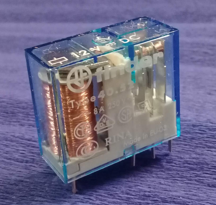
The Finder type 40-52 is an average size, mains-capable DPDT relay so it's a good basis. Someone might want to integrate one or a few to control mains-powered devices with a microcontroller, for example I suppose that most circuitjs users will not consider AC-driven coils (which it doesn't handle).
Rated at 12V, the coil resistance is about 200 ohms. I have 5 of them so here are the measured values :
208 211 211 205 207
Inductance is about a third of a Henry:
0.359H 0.362H 0.371H 0.364H 0.365H
I also tested one unit :
Von: 7.15V  Ion: 33mA
Voff: 2.2V Ioff: 10mA
Note that this is only one unit and the values move with temperature, which also depends on self-heating, meaning that the above values will drift a bit if left powered.
Also note that each contact can handle 8A of 220Vac so the magnetic circuits is pretty solid, with a strong spring, which also creates a high hysteresis and draws more current to action the contact.
-------------------------------------------------------------------------------------
I also found a small bag of smaller relays (1/3 the volume of the above type), still 12V but PCB-mount and can only handle 1Aac (so we can expect a softer spring). The coils average 720 ohms within some percents but the inductances are less clustered: 0.663H 0.619H 0.544H 0.675H 0.620H 0.656H 0.565H
 (one unit/sample only)
Ion:  9.7mA Von: 7.15V
Ioff: 12mA Voff: 1.45V
Whereas a similarly-rated but 5V only version has only 28mH and 122 ohms
-------------------------------------------------------------------------------------
So no, there is no "typical" relay just as there are no typical resistors or capacitors... At this point, it doesn't make sense to sample all my parts, but the above two references are "reasonable", as they are not guesses.
And concerning the switching time, I'll simply quote Paul:
I will change the switching time to 5ms. it's working great.
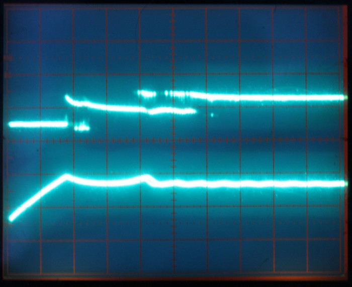
This parameter is useful in the context of the whole circuit but all the bounces and affecting conditions make this parameter almost irrelevant at this level of simulation. Bounces can have very complex patterns, the inductor will slow the rise of the current and delay the magnetism, oh and the speed might also be affected by the input current's slope so it is waaayyyy simpler to just give an approximate delay. @matseng has explored this with #ReTest - Relay timing tester and this is "another can of worms", as shown in an old log:
So this log does not answer the initial question but brings some interesting data to the debate :-)
-
Measure the potentiometer's position with Arduino
06/25/2021 at 15:23 • 0 commentsI happen to have a low-value pot whose position I should measure. It has a total resistance of 100 ohm: under 5V, that would draw 50mA ! That's ridiculous. Using a bridge would not be practical either because I need to read the position with the Arduino's ADC pin(s). I want to decrease the current by at least 10 folds yet preserve the 10-bit resolution and range.
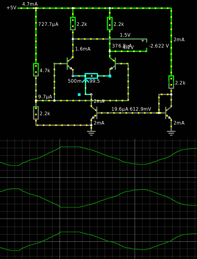
Then I had the idea to combine the pot with a classic differential amplifier, but not where it is usually plugged.
![]()
It took a while to find the "right" version because resistor values matter. It's a matter of balance as well :-) I have chosen 2K2 (and one multiple) so the overall current draw is 1/10th of 50mA but the values can be tuned (but check the output range). The biggest issue though was that the base bias has a significant influence (must be tuned so the output swing is maximised but current does not increase too much) and under certain conditions the swing "plateaus" in the middle position...
In the end, the circuit has 6 resistors of identical value and 4 identical NPN, that provide about 5V of peak-to-peak swing between the two outputs, which then go to an individual ADC pin (some integration and subtraction will do the rest of the magic). https://tinyurl.com/yeuvbcxq is where you can play at home !
Update
I built the circuit with 3K resistors and the output swing is within 2% of the simulation, or the tolerance of the parts and lab equipment. Good job :-)
-
The Golden Rules of Electronics
06/09/2021 at 15:43 • 0 commentsThrough the years I have identified recurring rules that underly most of my "bugs", "failures", "mishaps" and other blunders.
Rule 1 : If you connect it to the power supply, it works better.
.
Rule 2 If you connect it with the right polarity, it works even better.
.
You could argue "it goes without saying" but it goes better when you say it ;-)
Please comment and contribute with your own "golden rules" :-D -
Raspberry Pi is NOT Open Hardware.
01/14/2021 at 21:36 • 0 commentsJust a friendly reminder.
![]()
-
Hysteresis
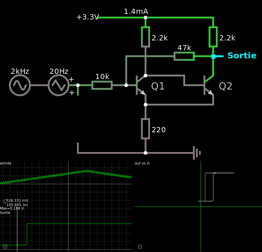
12/23/2020 at 01:35 • 1 commentPlaying with Fasltad's circuitjs to create a slightly better hysteresis circuit than the default circuit. It's crazy because changing any value affects the rest of the circuit.
![]()
The main difference is the feedback resistor, and a better choice of resistor values.
I tried to reduce the current draw and increase the hysteresis, which keeping convenient resistor values and decent logic levels (at least the low level is < Vbe at 3.3V).
That's if for today :-)
-
Thank you Jaromir !
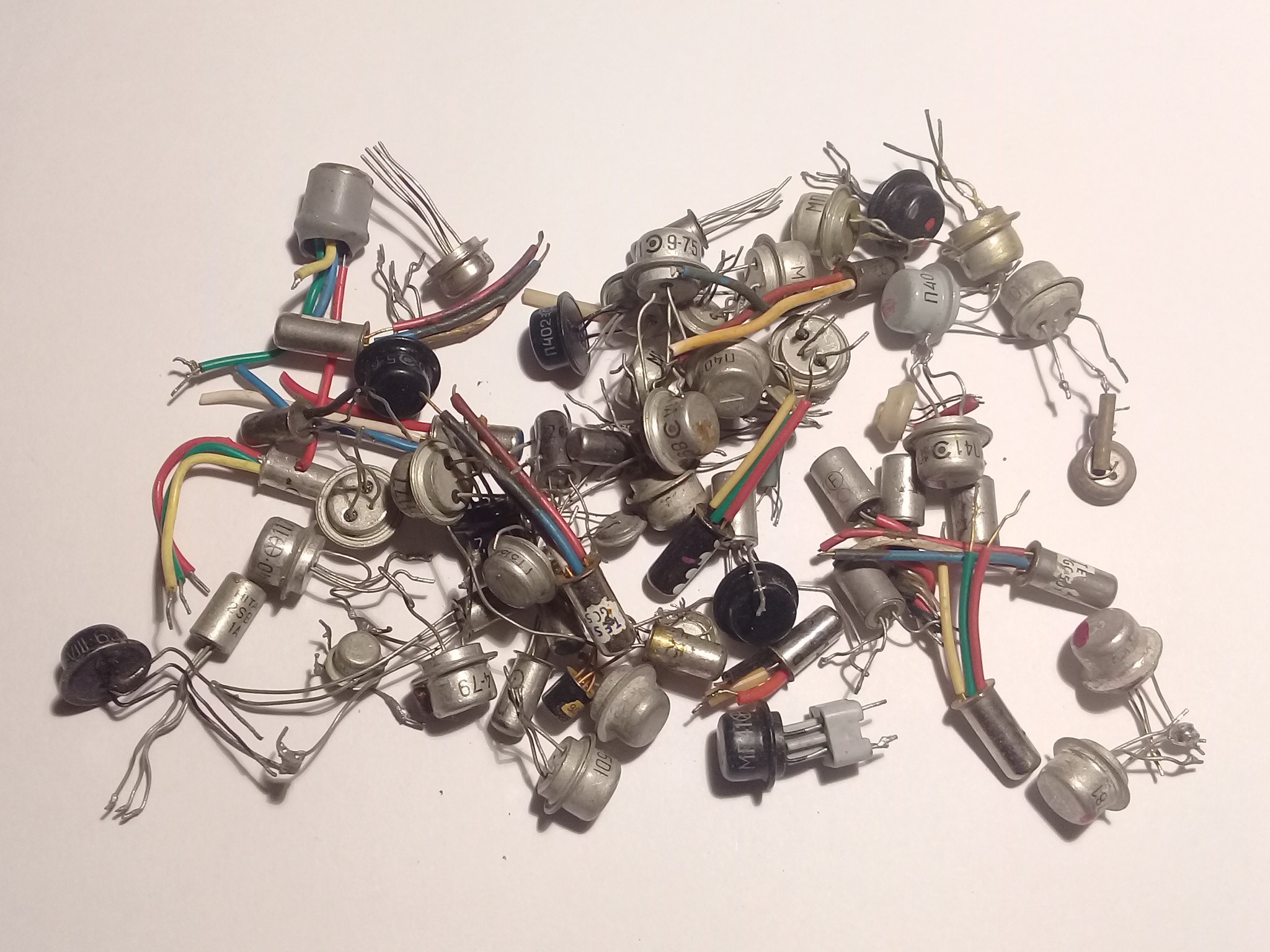
01/28/2020 at 23:36 • 2 commentsI received these yummies thanks to @jaromir.sukuba and it's only a tiny, tiny small part of the treasures he sent me !
![]()
Is it worrying that I now know half of these ridiculously obsolete parts ?
anyway I have enough of these to build a clock.
or two, maybe.
or a UART.
Damnit...
-
The damages of "Intellectual Property"
01/04/2020 at 14:06 • 1 commentHi @Drew Fustini :)
Here is something to integrate in your next slides about Free/Open Hardware designs :
From Apple Reunites With iPhone Graphics Chip Partner To License Technology (theverge.com)
Apple will once again license technology from Imagination Technologies, the chip designer that used to provide graphics processors for the iPhone and iPad, the UK-based company announced today. The Verge reports: In a short statement posted on its website, Imagination said that it had entered into a multiyear license agreement with Apple, under which the Cupertino, California-based firm will have access to "a wider range of Imagination's intellectual property in exchange for license fees." Apple announced its split from Imagination back in April 2017 when it said that it would start designing its own graphics chips, and it would stop licensing the company's technology within two years. After the split was announced, Imagination expressed skepticism that Apple could design its own chips "without violating Imagination's patents, intellectual property, and confidential information."
Did you read that last line right ?
So yes : using proprietary designs is a kiss of death.
You start by using some "IP cores" then you depend on them. When you want to switch to something else that you control 100%, you're already too dependent and too compromised by external information and NDAs. You get sued for doing your own stuff (or threatened) and you are forced back into the flock.
-
NéoRetroFriends in Paris
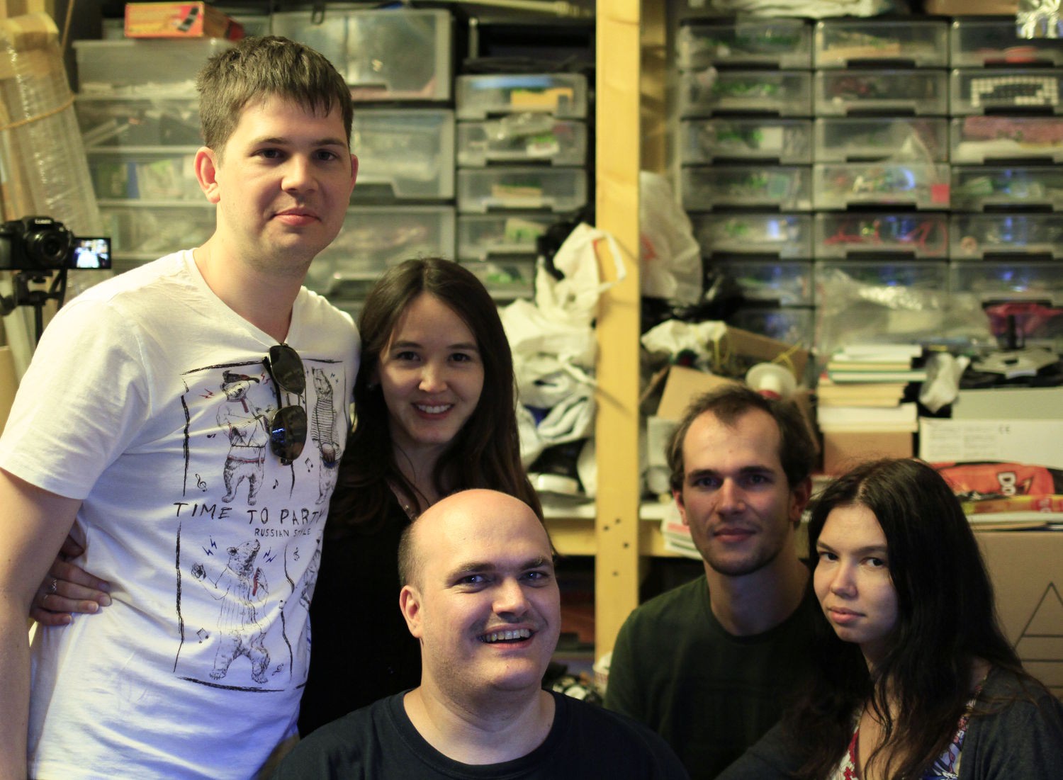
08/22/2019 at 20:02 • 5 commentsToday I had the incredible pleasure to welcome @Artem Kashkanov and his friend Roman !
They visited my workshop with their wives and we talked a lot about electronics, Russia, Russian electronics ;-)
We've been waiting for so long to meet and at last, we did ! Hopefully, we'll meet again, and who knows who else will be there too ? @Dr. Cockroach ? @Morning.Star ? @Drew Fustini ?...
Thanks again everybody !
-
Whygee goes MicroBit
05/06/2019 at 04:29 • 0 commentsMe being French for the kids :-P
-
Old joke
04/29/2019 at 12:07 • 0 comments![]()
Please make me a t-shirt with this :-P
-
I'm a "time nut" now !
01/24/2019 at 20:51 • 1 comment5ppb is not bad... it will only get better with time :-)
-
A Philips TCXO, model 4322-191
12/23/2018 at 03:16 • 7 commentsDISCLAIMER: I have no stable enough frequency source so the accuracy and stability are not tested here.
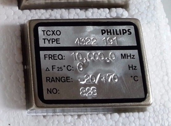
2 years ago, I have bought 3 of these crystal oscillators from eBay :
![]()
(picture courtesy of the seller bg2014-manue, thanks for the cross-linking !)
In theory, if the frequency drifts by less than 1Hz at 10MHz, that's in the ballpark of 0.1ppm (or 100ppb ?) but without a proper equipment, I can't validate the frequency accuracy and stability. I'm trying to solve this for a long time, if you remember my burned Rb oscillator :-D
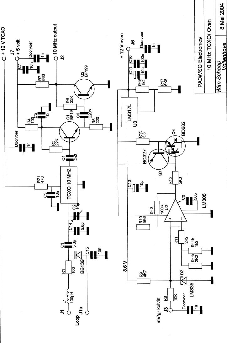
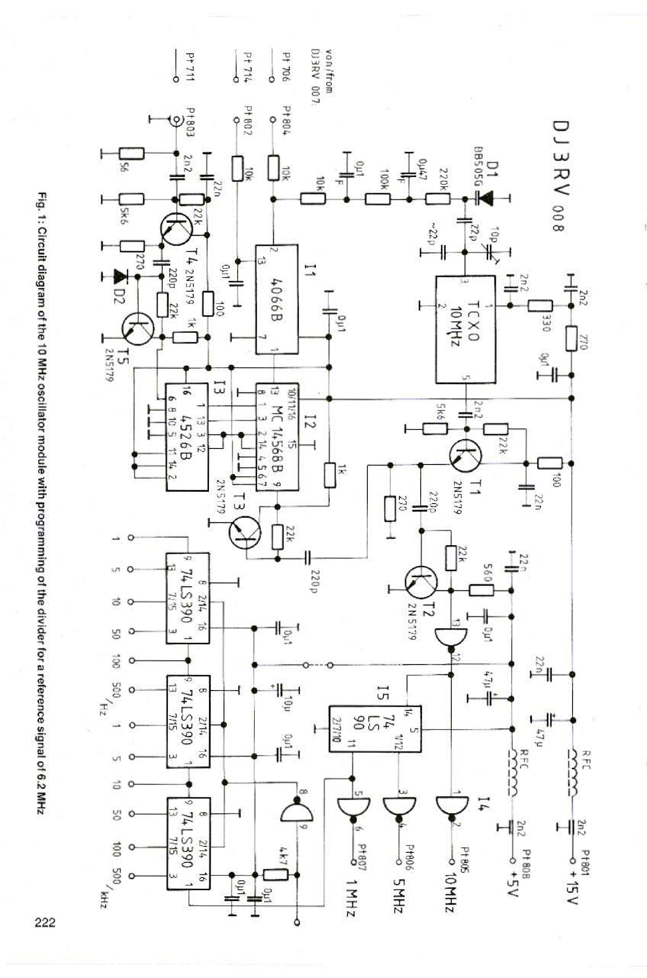
I think these Philips modules are a good compromise for price/performance/ease of use. Only recently did I test them so I went google-surfing. I could only find partial information but cross-checking different sources gave me some confidence about the pinout. For example the document "Frequentie standaard" by PA0WSO (in Dutch) gives a good example of how to use the module but the pinout is not defined.
![]()
The right hand half shows the temperature compensation, using a resistive element. A TEC could be used instead if ambient temperature rises above 25°C. The lower left quadrant shows the varicap control for tuning/"pulling" the oscillator.
Another useful document "A 10 MHz Timebase Clock for Frequency Counters - complete with a PLL for DCF77" shows the pinout but it might not apply to this variant : apparently there are several permutations but as long as you get the right VCC, GND and voltage, you can probe the pins with an oscilloscope.
![]()
If you get the pinout right, these 2 application documents help with the design of the pulling and amplification of the output.
A forum page shows the following pinout :
![]()
The assignation is correct BUT my specific model is not "pulled" by a resistor, but with added capacitance.
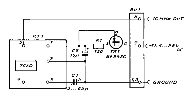
Luckily, Philips has used these modules in their own lab devices (PM6670 and PM6672) and they appear in the service manual :-) The above forum page provides the .djv file, along with other measurements. The TCXO is mounted on optional module PM9678B
![]()
WHY would the use a poor BF245 to handle 60mA ??? And here, the adjustment cap is on another pin...
The rest of the service manual shows the amplification but there is no heat management.
(if you find more references, I'll be happy to include them. I remember seeing a catalog/datasheet that shows the various pinouts and options but not it evades me)
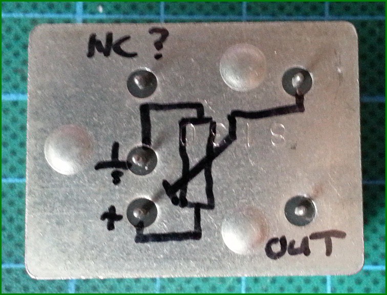
I measured a few things that I write down here. But first here is my pinout diagram for this specific model :
Don't connect the other pins.
- 0V : just the ground.
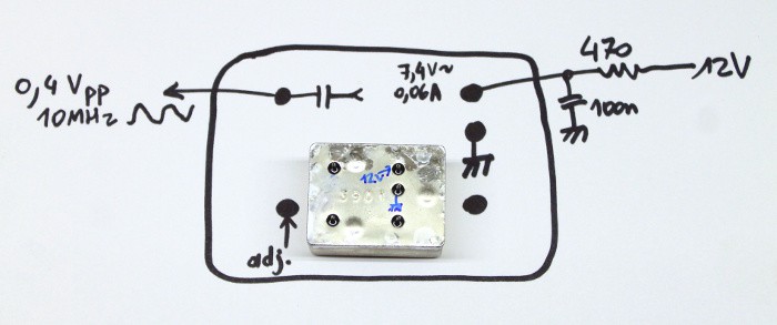
- Vcc : I don't know why there is a resistor. Maybe there is an internal shunt regulator but since the current increases with voltage, I doubt... The doc recommends 470 Ohms and 12V, but the 60mA drops the input to about 7.4V. I suppose these values will change with temperature, input ripple, and whatnot... Generous decoupling is recommended (ceramic+electrolytic ?).
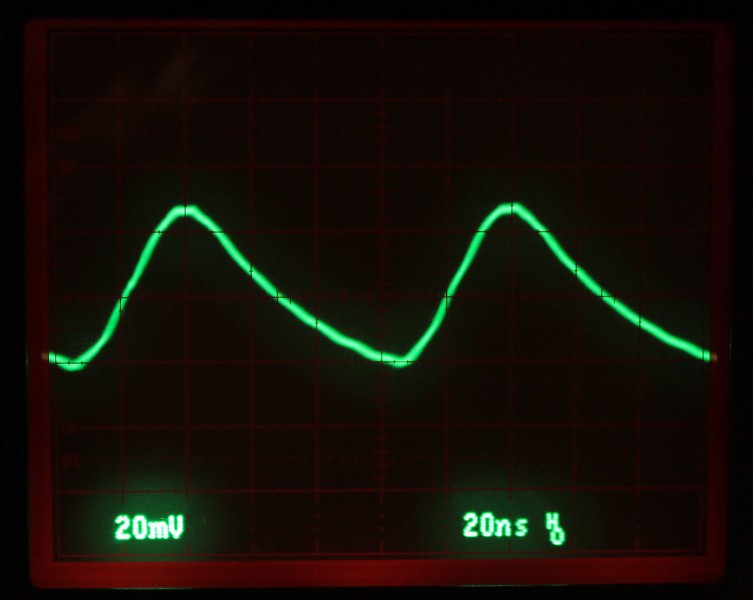
- The output: the 'scope shows it's 0V-centered, meaning there is an internal capacitive coupling. I also noticed the frequency slightly varying depending on output capacitance or impedance, I'm not sure... The amplitude is weak, buffer it with a high impedance amplifier (JFET input ?).
- There is another pin for adjustment, also called I.C. on some models. In this specific model, this is a capacitive pulling. I observe a lower voltage version of the output, don't touch this pin or you'll detune it... NOTE: FREQUENCY ADJUSTMENT IS NOT TESTED YET.
Here is how I quickly tested the CTXO :
Yes it's ugly but enough to check that it works :-)
When displayed on the 2467:
Here it's using a 10x setting for the probe so we might infer about 400 or 500mVpp. The amplitude and waveform vary significantly when using the 1x probe so impendance matters !
Looking with the DSO : amplitude is...
Read more -
Crazy filter
12/21/2018 at 05:35 • 0 comments -
Pun times...
11/21/2018 at 04:30 • 0 comments- Why don't you sleep ?
- "Because the night"
"Belongs to hackers"
"Because the night"
"Belongs to hacks"(old but gold)
-
Is "triode" a hardware protocol or a software protocol ?
11/06/2018 at 02:25 • 0 commentshttp://acedev.com/2014/314/index.shtml
You will love this webcomic !!!
![]()
And you can feel in the rest of the series that the author knows a lot about the subject ;-)
-
Still alive
10/14/2018 at 04:04 • 0 commentsDamn... The whirlwind of work (Python for kids and C for the startup) has taken me far from HaD and my other latest addiction (those damned ABS bricks from Billund) consume me... But I'm still estimating/evaluating/pondering processor things. Building a high-speed relay-based counter. Using all the PNP transistors I recently received. Writing more articles. Stuff like that.
My email notifications seem to be blocked as well :-(
It's good to see all your latest amazing projects, even though I lost touch with the contest. I remain a CPU hacker at heart !
-
More work !
08/10/2018 at 13:02 • 1 comment -
Ben Eater's Hexa decoder
07/28/2018 at 16:15 • 0 comments -
More work !
06/23/2018 at 12:41 • 3 comments -
Buck Mating Season 2018
03/18/2018 at 18:53 • 5 commentsBMS is back with version 2018 !
You already know the deal, go to these pages and click "Follow" and "Like".
If you have already, un-like and re-like :-)
ANGOLA
BCFJ
PDP
Y8
NumHex
Promer
FHP LGA
YGRECMOS
σα code
3RGB
YGREC-Si
PIC16F/OS
gdups
HYX
RD1000
Watchdog
Germanium-ECL
Whygeephone
Preamp
RemoteButtons
Morse Blinkies
MO5 interfaces
Thank you for your clicks !
Update :Thanks for your support ! I was able to order more parts and PCBs to progress with the projects !
-
Over 9000
02/27/2018 at 04:17 • 2 commentsI've been waiting for this pun so long...
But today it's over 9000.
![]()
-
Help with calibration of a digital lab PSU
07/27/2017 at 00:23 • 14 commentsI just found out that my new shiny cheap lab PSU is 5% to 10% off !
It has a nice resolution but the readings in both V and A don't match my measurements with an external multimeter...
The model AX6002P from Axiomet is similar to the better known Velleman or KORAD KA6002P so it might be a known issue....
Update 20170730:My "golden tester"'s battery is a bit low (8.5V) so I changed with a fresh one (curious since I changed it less than a year ago).
I tested the measurements against other multimeters, checked the power supplies and ... all values are coherent within the respective accuracies.
Bad battery. Case closed. Sorry for the alarm. But the question is still good and it would be cool to be able to calibrate the device "if something happened" :-)
-
Another eBay horror story
10/28/2016 at 15:20 • 0 commentsI have more than 400 stars and have purchased hundreds and hundreds of items on eBay.
I have had some occasional troubles and lately, more than before.
But even though the last story is worth a laugh (at my expense but only some tens of USD and at least I have very nice example of Chinese counterfeit gone wild) today's story is more of the "grieving" kind.
As some of you know, I've been bitten by the speed demon again. I want to play with discrete ECL gates and I need the fastest scope I can reasonably get (as if I needed an excuse to get the best gear for my lab). No DSO for me, because I don't trust them enough (at my price point at least), and it seems the fastest analog scope can reach 500MHz for some theoretical reasons (damned RC constants !). But even if I can't fully exploit the 500MHz "bandwidth" of the AF240, there can be all sorts of "very fast" circuits to design in the foreseeable future. For example, I have 250MHz SSRAMs and the lousy FPGA I use are rated up to 350MHz.
Recently I found an amazing deal: a Tektronix 2465 with original probes, anno 1995 is perfect condition, for a very affordable price and the shipping+customs was nice too. Sorry, no name, it was the last one of a batch... Very fast shipping (5 days from order to delivery), well packaged (sheets over sheets of bubble wrap), works great and will do for the coming 20 years (if I can hack the backup battery). Price: 150 USD, shipping: 42.64 USD, customs: 38.49USD. Total : 231.13 USD with expedited "international shipping program". A steal. Tek-love at first sight.
But 4×300MHz doesn't cut it and I have no idea what signals I'll have to treat in the coming decade or two. I need an analog speed demon. I looked around and the suspect is the Tektronix 11302, a modular "boat anchor" capable of 500MHz with bells, whistles and even a drum. The last of a long lineage of Tektro tradition. I found the service manual, looked at forums to get an idea and browsed eBay.
I found one in Italy (close to my French home) for about $300 and $60 shipping. Nice but only one 11A32 (2×400MHz) module. That doesn't scratch the surface. Looking at spare modules, I see that the price will climb quicky if I want to populate the other 2 free slots (one slot cover is missing, which is "no-no"-ed in the service manual, but that's a detail).
Then I found a well-equiped 11302 (not 11302A) with 2×11A32 (same 2×400MHz as above) and one 11A71 (1GHz@50 Ohms, yipeeee) in the USofA (but no probe). Seller writes: "Garanteed" and "use ebay's global shipping program". So I "bid in confidence". And win !
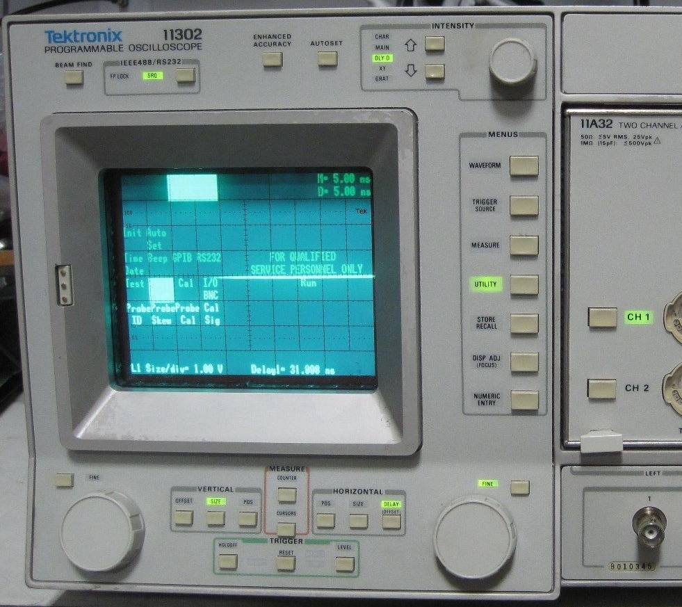
I'm elated by the 2465 and happy that it has a big brother, gotten for barely more: around 180$ only ! The seller has thousands of stars, the unit works, so what could go wrong ?

Let's start with the time taken to decide about shipment, which added a bit of suspense.
Some pictures:
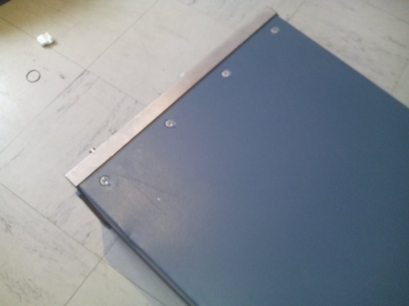
I find a peace of plastic while I remove the flakes. What can it be ? Oh, a foot...
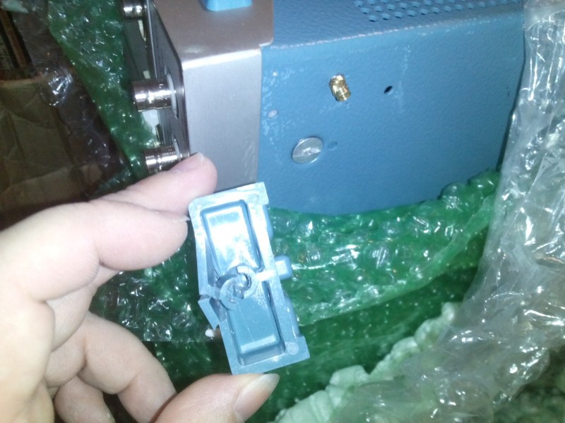
The unit still in the box, most of the flakes have been removed: there is only one layer of thin bubble wrap in the frond and in the back. One more layer around.
 Surprise: another foot is missing !
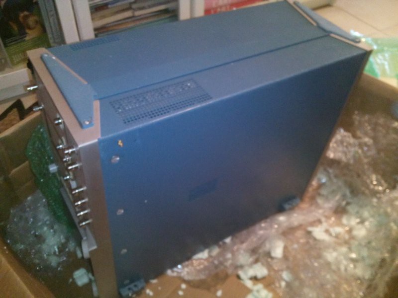
And the case shows a bump
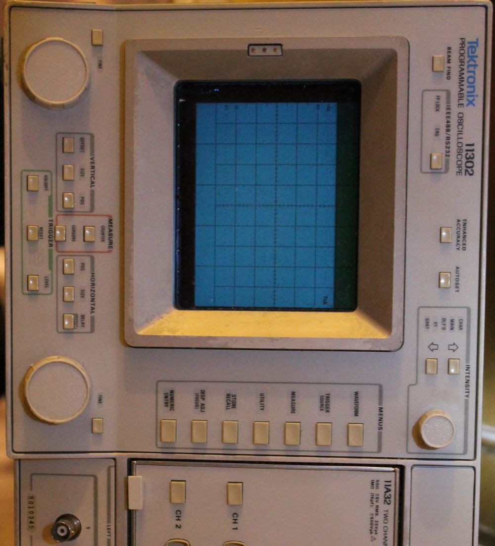
The unit sitting on it side. The screen is "falling" inside its frame. Not good!!!
The broken screen
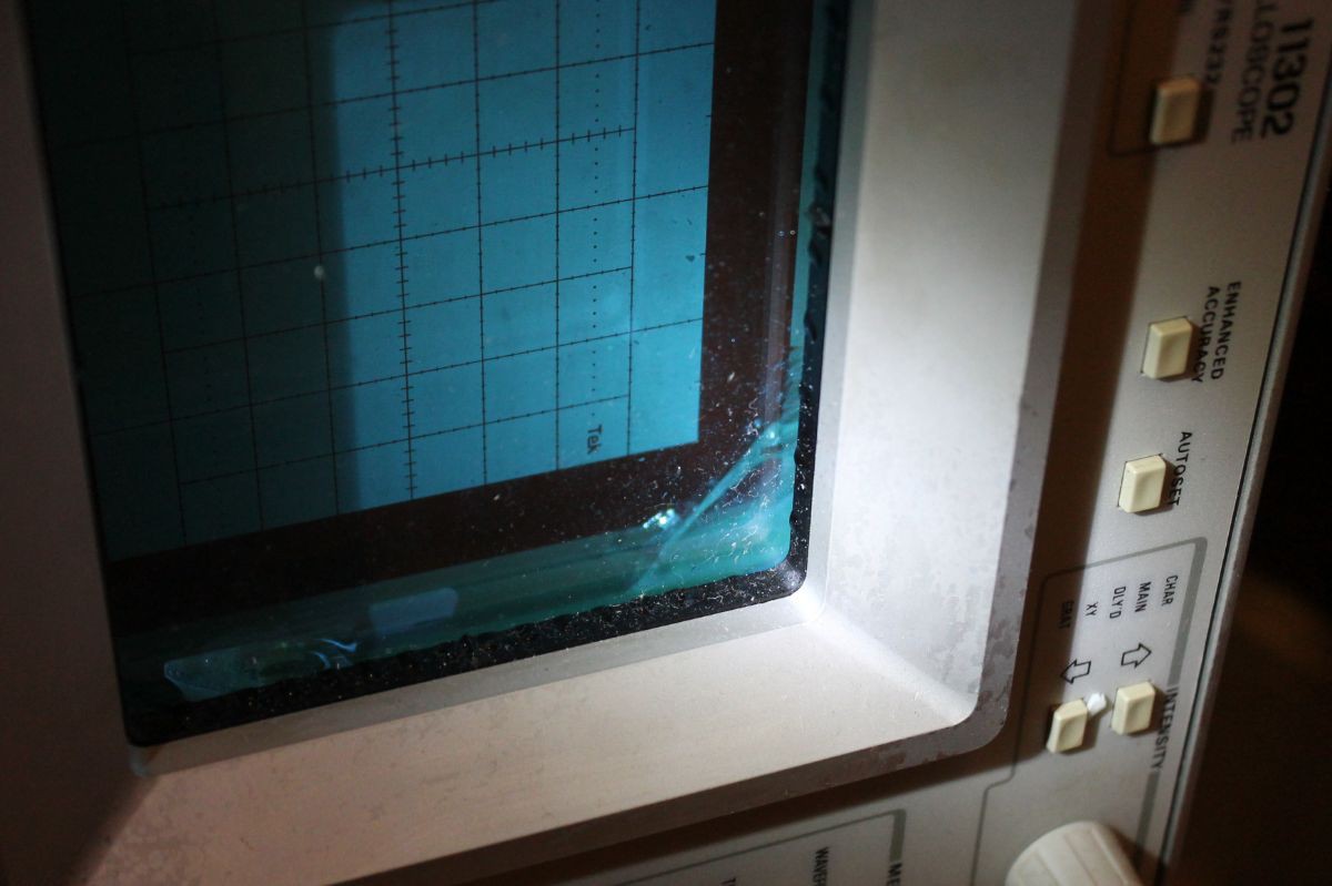
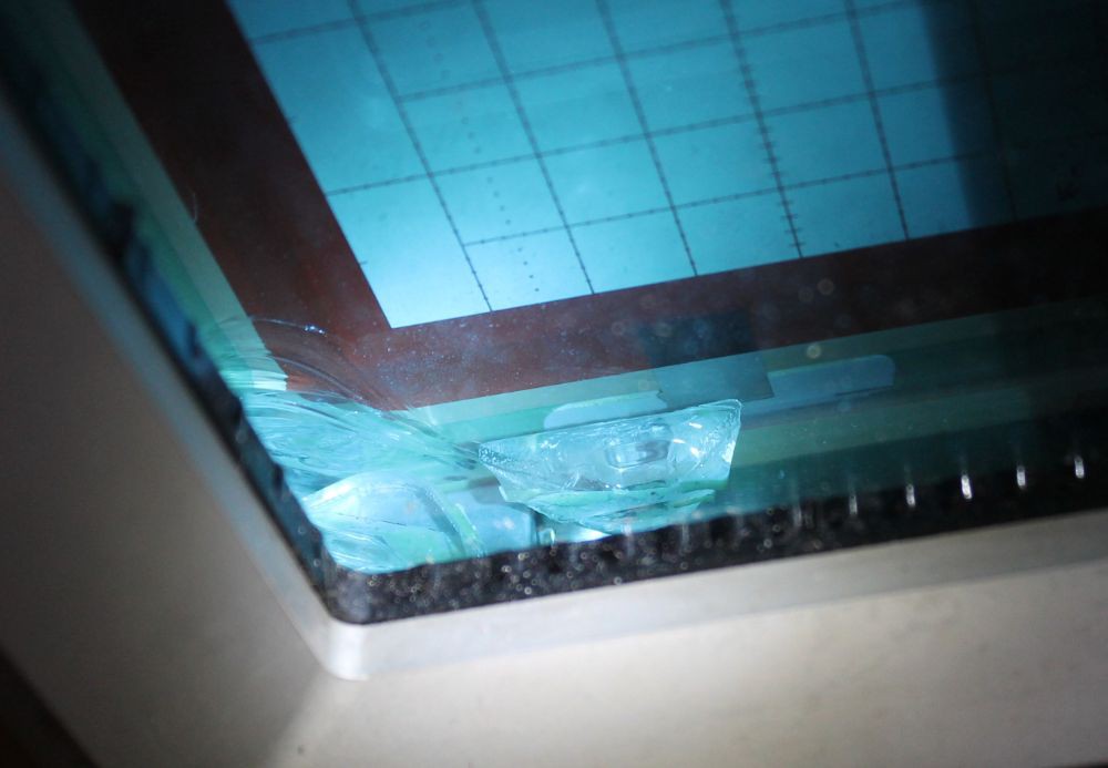
The tube is not repairable. Changing it requires a complete recalibration, if I ever find a spare part, which, for price, the would come as another complete unit...
The scope was obviously improperly packaged.
The cardboard box sustained most of the damage but was slightly deformed. Sorry I didn't think I should take a picture because I thought it was well protected inside.
The big mistake was with the filling. The unit should have been copiously wrapped in a lot of thick bubble wrap sheets. The previous scope (2465) came with bubble wrap only. Not only did protected the scope, but also created enough "pressure" inside the box to keep it rigid.
On the contrary, the flakes behaved like a "fluid" and moved around the...
Read more -
Oh the difficulty of sourcing P-MOSFET in TO-92
08/29/2016 at 02:42 • 4 commentsIf you follow Yet Another (Discrete) Clock, you know this project uses quite a lot of MOSFET in the easy-to-solder TO-92 package. A bit less than 500, including about 300 N-FET (BS170 or 2N7000) and the rest are P-FET (BS250).
The N-FET are OK: I could source 300×2N7000 for around 10$, 3 cents per piece is a nice deal and a decent price for the project.
The P-FET are another story :I could find cheap reels in SOT23 but the prices are much higher for the TO-92 package and there seems to be a sort of shortage in the usual cheap markets. Earlier this year, an order never made it to my home (among other postal problems) and a 200pc lot was found to have a reverse pinout (https://hackaday.io/project/9376-yet-another-discrete-clock/log/37927-it-was-too-easy).
This post is about another escalation in the BS250 horror story. I found a decently priced lot of 100 on eBay (due to Brexit) and this time ordered only one lot (I was not feeling rich, and at 20GBP, or about 24€ for 100, the unit price is almost 10× higher than the N-channel). Since the precedent lot (2×100) was functional (despite the reversed pinout) and was delivered, I bought from the same seller. Delivery was pretty fast (maybe due to summer vacations and less business) so I was ready to leave another good feedback.
Just to be sure, I tested a few parts from the bag. I don't remember why but you never know, and I wondered what was the pinout this time. Guess what ? I found a MOSET but in N-channel, not P. WTF ? It's marked "BS250" !
I take another then another and start to find a "mixed bag"
- Some parts are indeed P-channel but a minority
- Most are N-channel
- Some weird arrangements, like dual diodes, or very malformed junctions
- The surface of several packages look altered, like attacked by acid, and a couple have no marking. Others have a different style of marking...
After I sent a complaint to the seller, I received the following:
« Hi,client.So sorry for your trouble.Could you let me know how many pieces are not working as excepted,I will check with our supplier for this issue.Regards, Namedeleted »
Wait, you send me worse-than-counterfeit parts then you want me to do your job, for which I paid you ?
Alright, since you wanted it, let's waste 2 hours testing all the parts by hand.
I could identify:
- 25×P-channel (more or less BS250, I only tested the simplest parameters)
- 61×N-channel (some sort of 2N7000 but I didn't care about the pinout)
- The rest are malformed, non-functional parts.
Only 1/4 of the order can qualify as conform.
Ah, China...
Pictures to come...
-
Dangerous Prototypes vs DirtyPCB : same maker, different process
08/28/2016 at 03:36 • 11 commentsMy first 2 orders were to DirtyPCBs and were satisfying.
The 3rd was to Dangerous Prototypes because DirtyPCBs was down.
Both provide my required characteristics at very good prices : 0.6mm FR4, plated through holes, white mask, HASL finish. You'd think I'd get the same result, since they used the same factories, but I was surprised.
- First remark : DirtyPCB respected my milling to the letter. That was pretty cool :-) I gorget which diameter I asked (0.8mm ?) but it went well.
OTOH Dangerous Prototypes replaced my dashed milling to make a "classic milling" just as a normal panelized design. Pretty neat ! However I carefully selected the milling diameter because some boards have very tight dimensional margins. My caliper says around 0.8mm while I asked for 0.7mm. I'll see if it changes anything in practice... - Second remark : Dangerous Prototypes provides only a very low-resolution preview. DirtyPCBs provides high-resolution renderings that helped me get the first boards "right" at the first order.
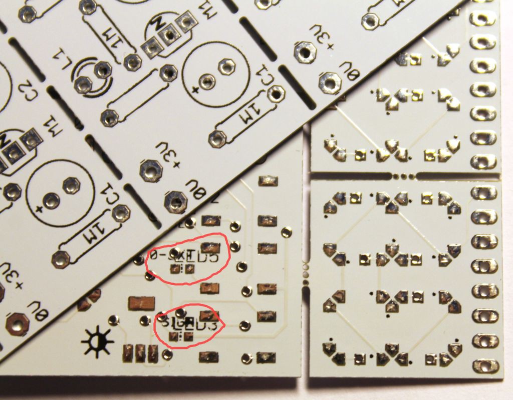
This matters a lot because (even though the previews are not binding) the markings are important for my display projects. And Dangerous Prototypes cluttered my PCB with the very badly autoplaced parts numbers. With fine pitch SMDs, it creates a mess.
Just have a look at these previews, generated in a second by DirtyPCBs before you commit/pay:
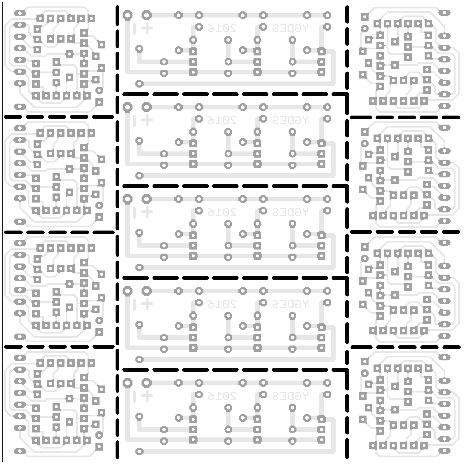
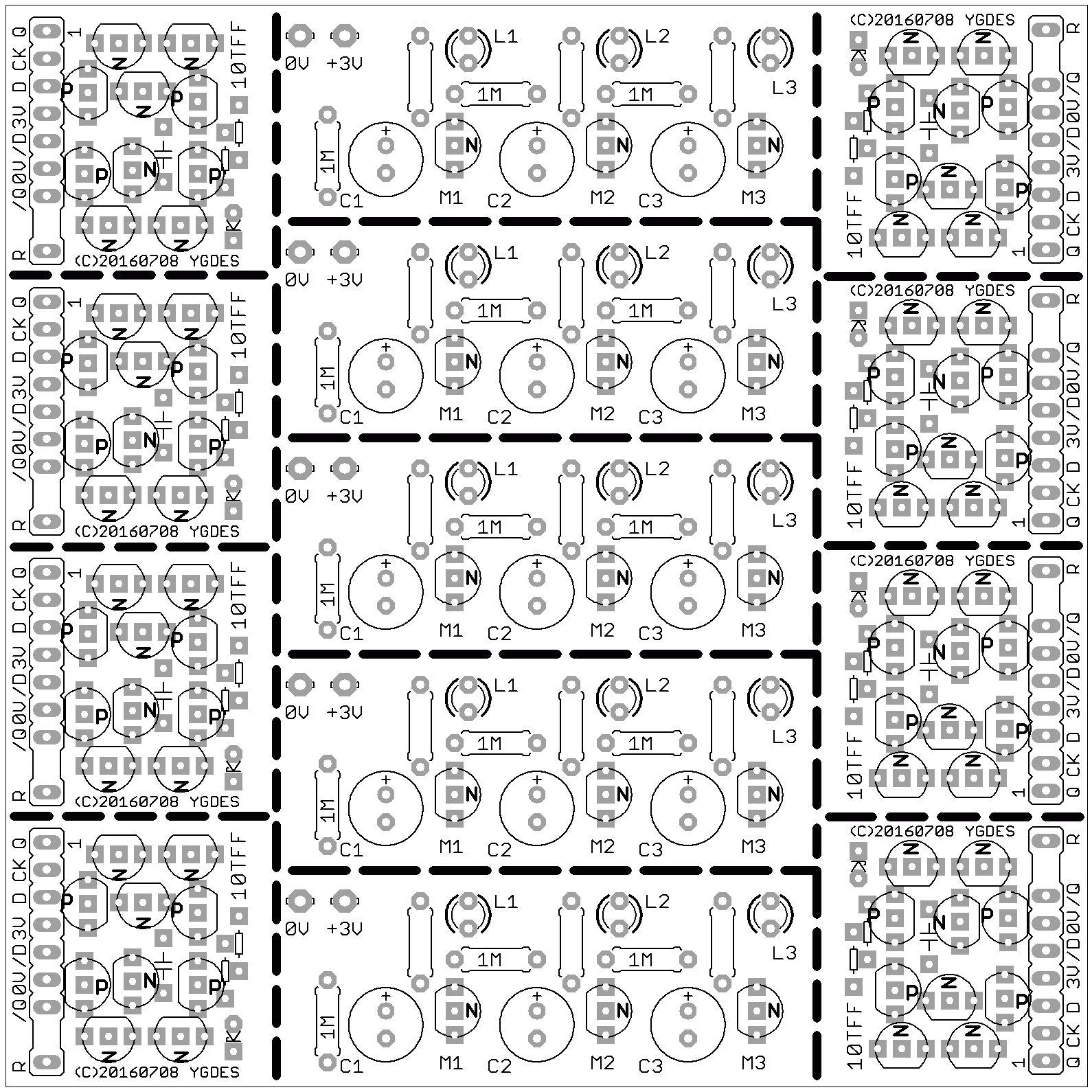
You can easily spot issues.
Now try this on this 150×150px thumbnail:
No higher resolution is provided...
- Third remark : In the same vein, I have chosen to cover the vias with mask to reduce visual clutter and reduce chances of shorts. Dangerous Prototypes ignored my DRC (well, not their fault, I didn't provide, but they didn't ask either) and my PCB "visible side" is sparkling with all the HASL vias.
Solution to 2) and 3) : provide GERBER files. This must be evaluated...
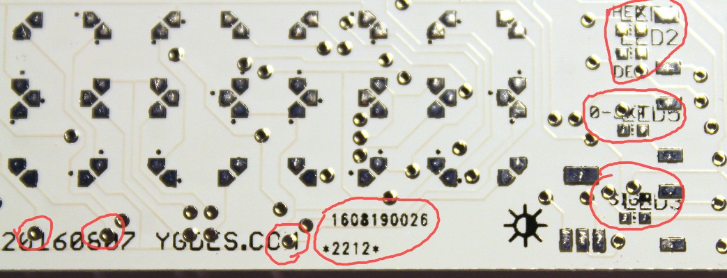
- 4th remark : Now, a pretty miffing discovery : Dangerous Prototypes placed a PCB reference number on the visible side of one of the panelised circuits. Half of my first #DYPLED boards now have an irrelevant string. Why put it on this side ? I should "reverse" the circuit so the markings can be located on the other side....
Let me state (again?) that there is nothing "wrong" with what Dangerous Prototypes did. It's just that the result is not "as I expected". Dangerous Prototypes might have manual intervention, or maybe it was processed and checked by a different operator but nothing was modified on both DirtyPCBs runs. This (and the good resolution of the preview) is why I favor them.
OTOH Dangerous Prototypes provides more options (flex for the win !)
Overall, I have tested the process and got fast delivery for a very reasonable price and I can prototype #DYPLED and others. 0.6mm FR4 is nice, no need to use finer boards. And I know how to make the PCB I want :-)
The following pictures show the actual circuits:
- Here we see the different style of milling, and the mess generated by points 2) and 3). The user markings are unreadable.
The #DYPLED circuit is way more sophisticated than the #Yet Another Electronic Lampyridae so I shouldn't be surprised that there are more opportunities to mess something up... That's what prototypes are for.
- The issues with the mask and silkscreen:
The vias are exposed, they mess with markings and will short signals, the parts references are printed and confuse the user markings, and a random, unwanted reference number is added...
- The circuits are actually automatically tested, as can be seen by the tiny dots (from the probes) on many pads. And the process works nicely with 250µ wide pads. Look at the following picture in high resolution:
#DYPLED can move forward but the tinned vias are a problem because the 4014 LEDs have exposed thermal pads that will be shorted to other signals. Furthermore, the thickness of the tin lifts the whole LED package, which will be harder to solder... At least I can test the Flash EPROM and all the semi-discrete circuits around it.
Then I'll order a new batch wich fixes the problems I've...
Read more - First remark : DirtyPCB respected my milling to the letter. That was pretty cool :-) I gorget which diameter I asked (0.8mm ?) but it went well.
-
Fans of The Big Bang Theory will understand
05/24/2016 at 01:51 • 0 commentsBoron
Arsenic
Indium
Gallium -
Buck mating season
04/15/2016 at 03:27 • 1 commentThe meme these days is bucks. They seem to multiply yet we can't catch them. Well that's because bucks run fast, and everyone likes a quick buck.
 The mating season will soon be over so let's stop and contemplate their majesty... before they run out.
Edit : all the bucks have been slaughtered. It was a cruel and frantic massacre. We can now all return to our usual activities. Roam In Peace.
-
A new kind of ... what ?
02/21/2016 at 05:25 • 2 commentsIn case you wondered what symbol I now use for my avatar:
 and no, I'm not a Star Wars fan. But the pun was too sweet
 -
Electronic stuff I won't use and don't want to throw away
12/01/2015 at 02:14 • 0 commentsMy workshop in Paris has accumulated many parts in the last decade but some of them have to go. I don't want to throw them away, recycle them or put them on eBay but somebody here could be interested for a swap/trade ?
I have:
- old Xilinx and Altera FPGAs, some pretty dull and others needing reballing
- Actel ProASIC Plus (APA) chips (QFP) and some associated development tools/gear (I thought they would be useful but ... no)
* 24× APA600 PQ208
* 15× APA075 FTQ100
* old Flashpro (parallel port)
- Actel ProASIC Plus (APA) chips (QFP) and some associated development tools/gear (I thought they would be useful but ... no)
- 16-bits and 32-bits ADi DSPs (including ADSP2181 and ADSP21065 40-bits FP in QFP)
- a bunch of x86 motherboards, in PC104, PICMG, ITX, ATX and ETX formats (what we used before the Raspberry Pi arrived)
- a few Rabbit Semiconductor modules...
I'll make a detailed list if requested.
- old Xilinx and Altera FPGAs, some pretty dull and others needing reballing

Yann Guidon / YGDES's pages
CPU architectures, entropy, algorithms, PCB, LED screens, FPGA, VHDL, C, ASM, HTML5... see http://ygdes.com and chat with me!


