-
How to Connect Water Flow Sensor with Arduino
06/30/2020 at 09:51 • 0 commentsWater management is very important in today’s time to tackle the water crises. Supplying water according to the real requirement is important and thus measuring water is a very essential step in water management systems. There are many water flow measurement techniques as well as different types of water flow meters used to measure the volume of water flow in pipelines but these all are too costly. Through this guide you will get an ideas for design and development of low-cost with the help of readily-available and low-cost water flow sensors.
YF-S201 Water Flow Sensor
Water Flow Sensor, as the name suggests, is a device to measure the flow of water. The Water Flow Sensor used in this project is shown in the image below.
Accurate flow measurement is an essential step both in the terms of qualitative and economic points of view. Flow meters have proven excellent devices for measuring water flow, and now it is very easy to build a water management system using the renowned water flow sensor YF-S201. This sensor sits in line with the water line and contains a pinwheel sensor to measure how much water has moved through it. There is an integrated magnetic Hall-Effect sensor that outputs an electrical pulse with every revolution.
Working of the Water Sensor
The sensor has 3 wires RED, YELLOW, and BLACK as shown in the figure below. The red wire is used for supply voltage which ranges from 5V to 18V and the black wire is connected to GND. The yellow wire is used for output (pulses), which can be read by an MCU. The water flow sensor consists of a pinwheel sensor that measures the quantity of liquid that has passed through it.
Basically, the YF-S201 Water Flow Sensor consists of a Flap Wheel (or a Turbine Wheel) that spins when water flows through the sensor. At the centre of this flap wheel, there is magnet fixed. Keeping this in mind, when the water flows through the YF-S201 Water Flow Sensor, the flap wheel spins due to the force of the water and as a result, the magnet attached to it will also spin. As a result, the magnetic field near the Hall-effect sensor switches polarity as the flap wheel spins and the output of the sensor (on the output Pin – Yellow Wire) will be a pulse.
By keeping track of the number of pulses from the output of the Water Flow Sensor, you can easily calculate the amount of water flowing through the sensor and as a result the Water Flow Rate.
Connections
- Connect the Red and Black wires of the YF-S201 Water Flow Sensor to +5V and GND.
- Since will be used the Interrupt feature of the Arduino, only Digital I/O Pins 2 and 3 are possible to connect to the Output of the Water Flow Sensor.
Code
The code for the Arduino Water Flow Sensor Interface is given below.
volatile int flow_frequency; // Measures flow sensor pulses
unsigned int l_hour; // Calculated litres/hour
unsigned char flowsensor = 2; // Sensor Input
unsigned long currentTime;
unsigned long cloopTime;
void flow () // Interrupt function
{   flow_frequency++;
}
void setup()
{   pinMode(flowsensor, INPUT);
     digitalWrite(flowsensor, HIGH); // Optional Internal Pull-Up
     Serial.begin(9600);
        attachInterrupt(0, flow, RISING); // Setup Interrupt
     sei(); // Enable interrupts
    currentTime = millis();
    cloopTime = currentTime;
}
void loop ()
{   currentTime = millis();
  // Every second, calculate and print litres/hour
     if(currentTime >= (cloopTime + 1000))
 {
  cloopTime = currentTime; // Updates cloopTime
    // Pulse frequency (Hz) = 7.5Q, Q is flow rate in L/min.
   l_hour = (flow_frequency * 60 / 7.5); // (Pulse frequency x 60 min) / 7.5Q = flowrate in L/hour
   flow_frequency = 0; // Reset Counter
   Serial.print(l_hour, DEC); // Print litres/hour
    Serial.println(" L/hour");   }
}
The output of the project is to display the quantity of water flowing through the sensor in litres per hour as shown below.
Since the output of the sensor is a pulse, by calculating the frequency of the pulse, we can...
Read more -
Arduino Based Calculator with Power Boost Module
06/29/2020 at 12:15 • 0 commentsDC-DC converters are widely used in portable electronic devices like mobile phones and laptops and are primarily powered with batteries. These applications consist of many sub-circuits which provide different voltage levels to different modules of the system. Today we will see one of the many projects in which a Boost converter comes in handy.
Calculators have become very important in todays time. In schools, colleges and even in many offices calculators are regularly used. They can be used to calulate different things and even in different number systems. Isn’t it exciting to have your own calculator? So, do you want to make your own calculator? Well, today you will get an idea on how to build your own basic calculator.
So let’s get started
- This project consists of DIY based keypad that works perfectly, an Arduino programmed 328p controller, LCD with I2C module, 3.3v to 5v boost circuit and perf-boards.
- Let's start with the keypad,
- Use and solder 8 push buttons which are arranged in such a way that they look like a real Arduino keypad.
- Use a male Berg connectors that can act as a jumper and also it acts as a conductor.
- These connector pins are connected to the Atmega 328p microcontroller with the help of L-shaped male headers. As you can see in the above photos that four pins act as rows pins while the other four pins act as columns.
- Now, let's discuss the mainboard. The mainboard consists of a micro-controller, a 16Mhz crystal oscillator, two 22pF non-polar capacitors, an I2C connector for LCD and a boost circuit as shown in the circuit below.
- As for the LCD, the I2C module is directly soldered on the LCD PCB, and there is no gap between them.
- The mainboard is powered by the 3.3v LiPo battery, the boost circuit converts the low voltage to the high voltage since there is the potentiometer connected on the boost circuit which varies the voltage at the output.
- So by varying it, the voltage can be changed, this micro-controller only requires about 5V, so the voltage is varied to 5V on the output. This voltage is also supplied on the I2C module this turns on the LCD.
4. The I2C module on the LCD consists of four pins which are connected in the following ways:5V -------- 5V (output of boost circuit)
· GND ---- GND (output of the boost circuit)
· SCL ------ A5 (SCL of Atmega 328p) Arduino
· SDA ----- A4 (SDA of Atmega 328p) Arduino
Code
Write the code in the Arduino platform and see if the calculator works
#include <LiquidCrystal_I2C.h>
#include <Keypad.h>
LiquidCrystal_I2C lcd (0x27, 16, 2);
const byte rows = 4;
const byte cols = 4;
char hexKeys [rows][cols] = {
{'1', '2', '3', 'A'},
{'4', '5', '6', 'B'},
{'7', '8', '9', 'C'},
{'*', '0', '#', 'D'}
};
byte rowPins[rows] = {4, 5, 6, 7};
byte colPins[cols] = {0, 1, 2, 3};
Keypad kpd = Keypad (makeKeymap(hexKeys), rowPins, colPins, rows, cols);
long number = 0;
char dynamicKeys;
String string = "";
boolean enterkey_state;
boolean binButton_state;
boolean hexButton_state;
boolean octButton_state;
boolean decButton_state;
void setup()
{
lcd.begin();
lcd.backlight();
lcd.clear();
lcd.setCursor(0, 0);
lcd.print("Initializing");
for (int i = 12; i <= 16; i++)
{
delay(200);
lcd.print("*");
}
delay(3000);
lcd.clear();
lcd.setCursor(0, 0);
lcd.print("Digital");
lcd.setCursor(0, 1);
lcd.print("Calculator");
delay(3000);
lcd.clear();
}
void loop()
{
enterkey_state = false;
binButton_state = false;
hexButton_state = false;
octButton_state = false;
...
Read more -
How to make DIY Power Bank 18650 LiPo Charger
06/27/2020 at 06:37 • 0 commentsIn recent years, the use of power banks has risen significantly as they provide a very convenient and easy method of charging smartphones and other devices when away from mains power. Wireless charging power banks have also been introduced for those devices that can be charged wirelessly.
But have you made a power bank? Well, you can now. With the help of DIY 18650 Lipo charger (refer the image) you can make your own power bank at your home. In this guide you will get to know how to make your own power bank at home with the help of a few electronic products.
What is a Power Bank?
Power bank is a battery pack which is used to charge a cellphone outdoors during emergency situations when an AC outlet is unavailable for charging the cellphone.
Power bank modules have gained significant popularity today due to their portability and ability to charge any cell phone while traveling and during emergency requirements.
It is basically a battery bank box which is initially fully charged by the user at home, and then carried outdoors while travelling. When the user finds his cellphone or smartphone battery reaching low, he connects the power bank to his cellphone for a quick emergency topping-up of the cellphone.
Ways of making a Power Bank with 2 Li-Ion Cells
The first circuit above makes use of a common collector transistor configuration for charging the intended cellphone device, the 1K preset is initially adjusted to enable a precise 4.3V across the emitter of the transistor.
The second design above uses a 7805 voltage regulator circuit for implementing the power bank charging function.
The last diagram here depicts a charger design using an LM317 current limiter. This idea looks much impressive than the above two since it takes care of the voltage control and the current control together ensuring a prefect charging of the cellphone.
The battery is to be connected to the motherboard B + negative-, installed against the necessary burning motherboard.
Thus you can make your own power bank with the help of Lipo charger Module. This module also has an LED Lamp display power which shows if the circuit is working or not. If the circuit is not working then the Lipo charger automatically shuts down to avoid loss of power. See more of this module and try making your own power bank.
This guide was written in reference to the blogs published by homemade-circuits.com.
-
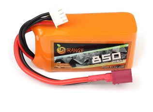
What is Lipo Battery and its Application?
06/25/2020 at 12:08 • 0 commentsWithout Lipo batteries drones probably wouldn’t exist today. With appealing attributes such as low weight, high energy density, and ever greater discharge rates, Lithium-Polymer (LiPo) batteries have transformed the electronic world. The emergence and continual improvement of these batteries has provided a significant performance boost in many electronic applications. These batteries have been gaining popularity and if used properly they can be used for a long run.
What is a Lipo Battery?
A lithium polymer battery, or more correctly lithium-ion polymer battery, is a rechargeable battery of lithium-ion technology using a polymer electrolyte instead of a liquid electrolyte. High conductivity semisolid (gel) polymers form this electrolyte. These batteries provide higher specific energy than other lithium battery types and are used in applications where weight is a critical feature, like mobile devices and radio-controlled aircraft.
Just as with other lithium-ion cells, LiPos work on the principle of intercalation and de-intercalation of lithium ions from a positive electrode material and a negative electrode material, with the liquid electrolyte providing a conductive medium. To prevent the electrodes from touching each other directly, a microporous separator is in between which allows only the ions and not the electrode particles to migrate from one side to the other.
Why are Lipo batteries used?
When compared to their old NiCd/NiHm batteries, there are 3 main points that make them a better option:
- Have nearly double the capacity with half the weight of NiCd or NiMH battery packs
- Retain charge significantly longer than NiCd or NiMH batteries when not being used
- With LiPo cells in combination of series and parallel, LiPo packs can be built to power most all RC aircraft.
We use Lithium Polymer batteries in drones or any other multirotor systems as well as in fixed wing drones. The same batteries are used in our smart phones.
BLDC motors needs high current or a burst of current for a moment. This high current flow capacity depends on the discharge rate of a particular battery. So, here, one thing gets confirm that you need a battery with high discharge rating which is described on a battery with a suffix “C” (30C). So that 30 C is discharging rate. This is something that you can get from Lithium Polymer batteries. The other advantage of LiPo battery is, they have higher mAh capacity.
Moreover, your requirements of higher mAh as well as higher current flow gets fulfilled by the batteries that are low in weight.
These are the reasons why LiPo batteries are used in drones.
Lipo batteries are used in many devices. Some of them are: -
- Health & Fitness Devices
- Phone & Accessories
- High-tech Smart Design.
- Drones
- PCs/Laptops.
Most modern LiPo chargers use something called balance charging. Balance charging is just a way of monitoring the voltage on each of these cells and charging them individually. It is the best way to recharge these batteries. Chargers that have balance charging take care of this automatically. Sometimes batteries are decided by its AH factor to know what is AH in Battery click here!
Thus now that you have got an insight on how Lipo battery works. See More of Lipo batteries and make your hobbies come true.
This guide has been written in reference to the blogs published by Wikipedia and learningrc.com
-
How to connect Voltage Sensor with Arduino
06/24/2020 at 11:37 • 0 commentsOne of the most important electrical measurements in most of these electronic devices is voltage. Measuring voltage is very important in projects/applications as giving wrong voltage to a device can lead to extreme malfunction of the device and the project. With this in mind Voltage Sensor module was created. It measures voltage and now there are different sensor modules which calculates voltages of different ranges.
A voltage sensor is a sensor is used to calculate and monitor the amount of voltage in an object. Voltage sensors can determine both the AC voltage and DC voltage level. The input of this sensor can be the voltage whereas the output is the switches, analog voltage signal, a current signal, an audible signal, etc. The pin diagram of the voltage Sensor Module is given below: -
The advantage of voltage sensors include:
- Small in weight and size.
- Personnel safety is high.
- Degree of accuracy is very high.
- It is non-saturable.
- Wide dynamic range.
- Eco-friendly.
- It is possible to combine both the voltage and current measurement into a single physical device with small and compact dimensions.
Working of the Voltage Sensor Module
Voltage Detection Sensor Module is a simple and very useful module that uses a potential divider to reduce any input voltage by a factor of 5. This allows us to use the Analog input pin of a microcontroller to monitor voltages higher than it capable of sensing. For example, with a 0V - 5V Analog input range, you are able to measure a voltage up to 25V. This module also includes convenient screw terminals for easy and secure connections of a wire. The Voltage Sensor is basically a Voltage Divider consisting of two resistors with resistances of 30KΩ and 7.5KΩ i.e. a 5 to 1 voltage divider.
The following image shows the schematic of the Voltage Sensor Module with an input voltage limit of 25V.
How to use Voltage Sensor Module
Now that we have seen a little about the Voltage Sensor, let us now proceed with interfacing a Voltage Sensor with Arduino and measure some external voltages.
The Arduino Voltage Sensor Interface is pretty straight forward.
- Connect the voltage to be measured to the screw terminal of the Voltage Sensor, connected the output of the voltage divider to the Arduino. That’s it.
- After interfacing the Voltage Sensor with Arduino, you can view the results on the serial monitor of the Arduino IDE.
Input and output can be calculated by using the following code: -
float Vout = 0.0;
float Vin = 0.0;
float R1 = 30000;
float R2 = 7500;
Vin = Vout * (R2/(R1+R2))
Vout = (analogvalue * 5 / 1024);
The application of voltages sensors include:
- Power failure detection.
- Load sensing.
- Safety switching.
- Temperature control.
- Power demand control.
- Fault detection.
Voltage sensors are included in many of the best Arduino starter kits, as they are very useful in many electronics projects. Get Additional Information on Voltage Sensor Module and keep your electronic projects safe.
This voltage sensor module is very useful in finding the voltage of a battery. If you want to know more specifications about the battery like what is AH, WH and other technicalities Click Here.
This blog has been written in reference to the blogs published by electronichubs.org and components101.com.
-
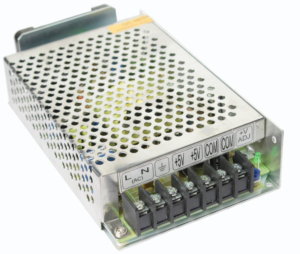
What is SMPS – Working, Applications.
06/16/2020 at 06:32 • 0 commentsThe term SMPS is often heard and you might have also seen it being used in different applications like computers, mobiles, battery chargers, vehicles, etc. But what does the term SMPS mean, what is its working and why is it being used very often in various applications. Well, all your doubts will be cleared through this guide.
SMPS
SMPS or Switched Mode Power Supplyis an electronic power supply that incorporates a switching regulator to convert electrical power efficiently. Like other power supplies, an SMPS transfers power from a DC or AC source to DC loads, such as a personal computer, while converting voltage and current characteristics. Switching regulators are used as replacements for linear regulators when higher efficiency, smaller size or lighter weight are required. As a result of their performance, switch mode power supplies are used in all but the most exacting applications to provide an efficient and effective source of power for most forms of electronic systems.
![]()
Switch mode power supply, SMPS, technology may be referred to by a number of similar terms. While they all look at the same basic technology, they refer to different elements of the overall technology:
- Switch mode power supply, SMPS: The term switch mode power supply is generally used to indicate an item that can be connected to the mains, or other external supply and used to generate the source power. In other words it is a complete power supply.
- Switch mode regulator: This typically refers just to the electronic circuit that provides the regulation. A switch mode regulator will be part of the overall switch mode power supply.
- Switch mode regulator controller: Many switch mode regulator integrated circuits do not contain he series switching element. This will be true if the current or voltage levels are high, because an external series switching element would be able to better handle the higher current and voltage levels, as well as the resultant power dissipation.
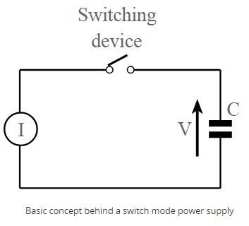
SMPS Basic Working
The basic concept behind a switch mode power supply or SMPS is the fact that the regulation is undertaken by using a switching regulator. This uses a series switching element that turns the current supply to a smoothing capacitor on an off.
![]()
The time the series element is turned on is controlled by the voltage on the capacitor. If it is higher than required, the series switching element is turned off, if it is lower than required, it is turned on. In this way the voltage on the smoothing or reservoir capacitor is maintained at the required level.
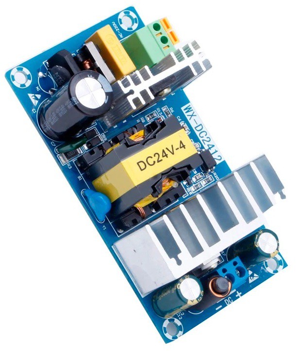
SMPS Advantages
- High efficiency: The main advantage of the switching power supply is greater efficiency than linear regulators because the switching transistor dissipates little power when acting as a switch.
- Compact: As a result of the high efficiency and low levels of heat dissipation, the switch mode power supplies can be made more compact. Also it has lighter weight due to the elimination of heavy line-frequency transformers, and comparable heat generation.
- Costs: one of the points that makes switch mode power supplies very attractive is the cost. The higher efficiency and the switching nature of the design means that the Standby power loss is often much less than transformers and this reduces costs.
- Flexible technology: Switch mode power supply technology can be used to provide high efficiency voltage conversions in voltage step up or "Boost" applications or step down "Buck" applications.
SMPS Applications
- The switch mode power supply (SMPS) is used in personal computers.
- It is used in machine tool industries.
- The SMPS is used in security system.
- It is used in railway system.
- It is also used in mobile.
- It is used in battery charger.
- The SMPS is used in vehicles.
![]()
SMPS battery chargers plays a vital role for the durability of many industrial...
Read more -
Why is SMPS Important
06/16/2020 at 06:23 • 0 commentsIn the age of energy-efficient devices, the poor efficiency rating of a power supply can be a deal-breaker. The solution that you finally choose depends on your requirements for efficiency, cabinet space, output regulation, transient response time, and cost.
SMPS
SMPS or Switched Mode Power Supplyis an electronic power supply that incorporates a switching regulator to convert electrical power efficiently. Like other power supplies, an SMPS transfers power from a DC or AC source to DC loads, such as a personal computer, while converting voltage and current characteristics. Switching regulators are used as replacements for linear regulators when higher efficiency, smaller size or lighter weight are required. As a result of their performance, switch mode power supplies are used in all but the most exacting applications to provide an efficient and effective source of power for most forms of electronic systems.
![]()
Importance and Applications of SMPS
Switched-mode power supply units in domestic products such as personal computers often have universal inputs, meaning that they can accept power from mains supplies throughout the world, although a manual voltage range switch may be required. Switch-mode power supplies can tolerate a wide range of power frequencies and voltages.
![]()
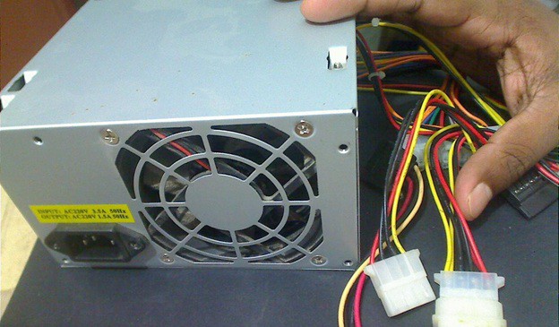
In the above image we can see an SMPS which is used in personal computers with the input, output, and fan cords visible.
Switched-mode power supplies are used for DC to DC conversion as well. In automobiles where heavy vehicles use a nominal 24 VDC cranking supply, 12 V for accessories may be furnished through a DC/DC switch-mode supply. This has the advantage over tapping the battery at the 12 V position (using half the cells) that all the 12 V load is evenly divided over all cells of the 24 V battery. In industrial settings such as telecommunications racks, bulk power may be distributed at a low DC voltage (from a battery back-up system, for example) and individual equipment items will have DC/DC switched-mode converters to supply whatever voltages are needed.
A common use for switched-mode power supplies is as extra-low-voltage sources for lighting, and for this application they are often called "electronic transformers".
Hence if not for SMPS we wouldn’t have laptops, computers and battery chargers which keep our electronic devices running and charged. Also the stepping up and stepping-down the AC/DC voltages have come in handy in many electronic devices. Know More of SMPS and explore the world of power supplies and make a project or work out an application of it.
-
LCD Display Module
06/15/2020 at 07:36 • 0 commentsThe LCD Display Modules have been used in many embedded projects the reason being its cheap price, availability and programmer friendly. Most of us would have come across these display modules in our day to day life but do you know how they work? Also want to know how to interface it with Arduino one of the most popular Development boards?
Well today in this blog you will get an insight on what is an LCD Module, how these modules work and what connections have to be made with Arduino and the display module.
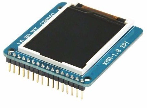
![]()
LCD Module
A liquid-crystal display (LCD) is a flat-panel display or other electronically modulated optical device that uses the light-modulating properties of liquid crystals combined with polarizers. Liquid crystals do not emit light directly, instead using a backlight or reflector to produce images in color or monochrome. LCDs are available to display arbitrary images (as in a general-purpose computer display) or fixed images with low information content, which can be displayed or hidden, such as preset words, digits, and seven-segment displays, as in a digital clock.
![]()
Working of LCD
The backlight in liquid crystal display provides an even light source behind the screen. This light is polarized, meaning only half of the light shines through to the liquid crystal layer. The liquid crystals are made up of a part solid, part liquid substance that can be "twisted" by applying electrical voltage to them. They block the polarized light when they are off, but reflect red, green, or blue light when activated.
Each LCD screen contains a matrix of pixels that display the image on the screen. Early LCDs had passive-matrix screens, which controlled individual pixels by sending a charge to their row and column. Modern LCDs typically use active-matrix technology, which contain thin film transistors, or TFTs. These transistors include capacitors that enable individual pixels to "actively" retain their charge. Therefore, active-matrix LCDs are more efficient and appear more responsive than passive-matrix displays.
Advantages of an LCD’s:
- LCD’s consumes less amount of power compared to CRT and LED
- LCD’s are consist of some microwatts for display in comparison to some mill watts for LED’s
- LCDs are of low cost
- Provides excellent contrast
- LCD’s are thinner and lighter when compared to cathode-ray tube and LED
![]()
Interfacing with Arduino
In Arduino based embedded system design, the Liquid Crystal Display modules play a very important role. Hence it is very important to learn about how to interface LCD with an Arduino. Since the most commonly used 16x2 LCD Module we will be having a look on how to interface Arduino with this module.
![]()
The 16×2 liquid crystal display contains two horizontal lines and they are used for compressing the space of 16 display characters. In inbuilt, the LCD has two registers which are described below.
- Command Register
- Data Register
Command Register: This register is used to insert a special command in the LCD. The command is a special set of data and it is used to give the internal command to the liquid crystal display like clear screen, move to line 1 character 1, setting the curser and etc.
Data Register: The data registers are used to enter the line in the LCD
Connections
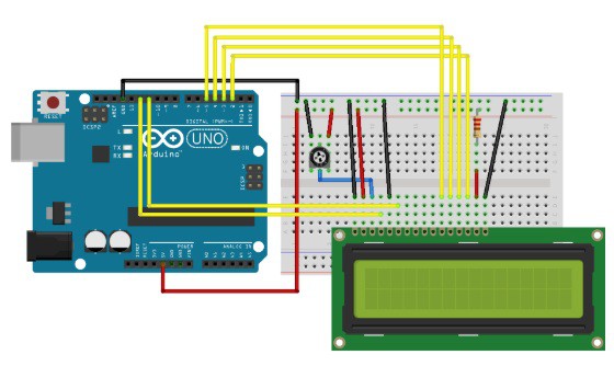
The following diagram shows how to interface an LCD Module with an Arduino.
![]()
From the circuit diagram, we can observe that the RS pin of the LCD is connected to the pin 12 of the Arduino. The LCD of R/W pin is connected to the ground. The pin 11 of the Arduino is connected to the enable signal pin of LCD module. The LCD module & Arduino module are interfaced with the 4-bit mode in this project. Hence there are four input lines which are DB4 to DB7 of the LCD. This process very simple, it requires fewer connection...
Read more -
How to choose Raspberry Pi Display
06/12/2020 at 14:31 • 0 commentsRaspberry Pi has become important over the past few years. The Raspberry Pi boards and its accessories come in very handy and a lot of projects and applications can be done using them. One such crucial accessory is the Raspberry Pi display. Without it there would be no screen and it would be really awkward to have a project without any screen in it.
Today I will list out some parameters which will help you to decide the best Touch Display for your Raspberry Pi.
![]()
Raspberry Pi Display
Raspberry Pi touchscreen is a display switched on the Raspberry Pi for users to operate the system on the screen by fingers. It contains two types of Raspberry Pi touchscreen. One is the resistive touchscreen, the other is the capacitive touchscreen. The vital difference between them is that the capacitive touchscreen can support multi-point touch while resistive touchscreen cannot. Both of them have a good expression of sensitivity.
![]()
The parameters that can be considered while choosing your Raspberry Pi display are:
- Screen Resolution
- Board for use with
- Touch Panel
Screen Resolution
The image on your computer screen is built up from thousands or millions of pixels. The screen creates the image you see by changing the colours of these tiny square elements. The screen resolution tells you how many pixels your screen can display horizontally and vertically. Screens that are different sizes can still have the same screen resolution. If you're comparing two screens of the same size but with different resolutions, the screen with the higher resolution (that's the one with more pixels) will be able to show you more of what you're working on, so you don't have to scroll so much. Because that screen has more pixels, the image will be sharper.
However, the higher resolution also means that elements on the screen - like icons and text - will look smaller. When you're choosing a new computer or display monitor, don't let yourself be guided by screen resolution alone. Brightness and colour representation can vary across screens thus choose the best screen resolution for your project or the particular application you will be using it for.
Board For use with
Choosing the right Touch Display for the right board is very important. The display interface for each Touch displays varies. Some have it through HDMI, USB, Display ribbon cable, etc. Though most of the Raspberry Pi Boards have the basic interfaces like HDMI, USB but it is at the same time important to choose the right Display for the right Board. It should be compatible with the board and the purpose of the use of the Display should be clear.
Touch Panel Type
Resistive touchscreens rely on the pressure of your fingertip – or any other object – to register an input. These touchscreens consist of two flexible layers with a gap of air gap in-between.
Rather than relying on pressure, capacitive touchscreens instead sense conductivity to register input – usually from the skin on your fingertip. Because you don’t need to apply pressure, capacitive touchscreens are more responsive than resistive touchscreens.
Resistive touchscreen advantages include:
- Lower cost to manufacture
- Higher sensor resolution—you can tap small buttons easier with just your fingertips
- Fewer accidental touches
- Can sense any object touching the screen hard enough
- More resistant to the elements like heat and water
Capacitive touchscreen advantages include:
- More durable
- Sharper images with better contrast
- Provide multi-touch sensing
- More reliable—will even work when the screen cracks (until you replace the touchscreen)
- More sensitive to light touch
The choice to use a capacitive or resistive touchscreen depends largely on the application for the device. Also the Size and the display technology depends sorely on the purpose of the Raspberry Pi Display. TFT Display can be used for normal...
Read more -
Raspberry Pi Display
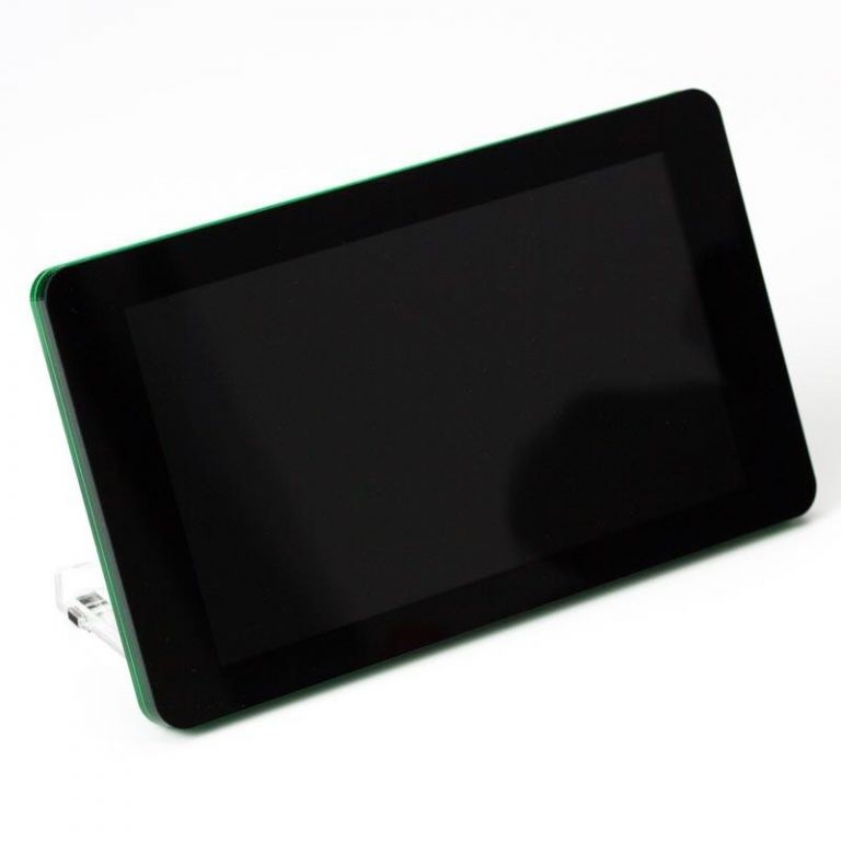
06/12/2020 at 14:16 • 0 commentsRaspberry Pi’s importance and its applications has grown over the years since its inception. The number of applications that their boards can be used in is immense. Their accessories have also come in handy a lot of times. One of them is the Raspberry Pi Display. Wouldn’t it be awkward to have no screen of your computer? Well Raspberry Pi display can be used for that. They can be also used in many projects / applications like building your own photo frame, bench computer, smart mirror etc. through Raspberry Pi.
Through this guide you will go through how to connect a Raspberry Pi display to the Raspberry Pi board.
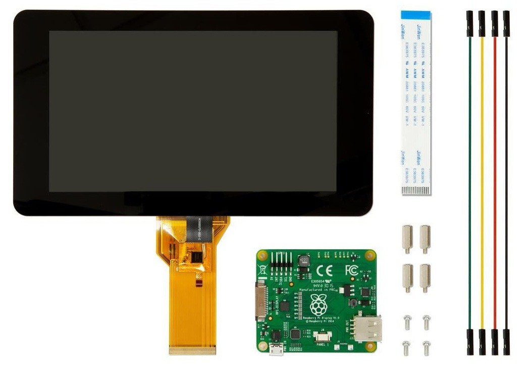
![]()
Raspberry Pi display
The Raspberry Pi Display is an LCD display which connects to the Raspberry Pi through the DSI connector. In some situations, it allows for the use of both the HDMI and the LCD displays at the same time.
![]()
DSI (Display serial interface) is a high-speed serial interface based on a number of (1GBits) data lanes. The total voltage swing of the data lines is only 200mV; this makes the electromagnetic noise created and power consumed very low. Unfortunately, DSI displays are only really created and sold for special purposes (i.e. when a mobile phone manufacturer wants to make a new phone), and although they can be available to buy, manufacture of the devices is subject to the lifetime of the phone!
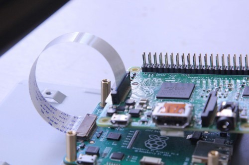
Connections
You will have to attach the Raspberry Pi Board to the back of the display. The Raspberry Pi has a small connector for a 15-pin ribbon cable which supports the Display Serial Interface (DSI) standard which allows for high-speed communication between LCD screens. Connecting up the display is fairly straight forward, it’s designed so that the Pi can be mounted on the back of it with all of the cables tucked away nice and neatly.
![]()
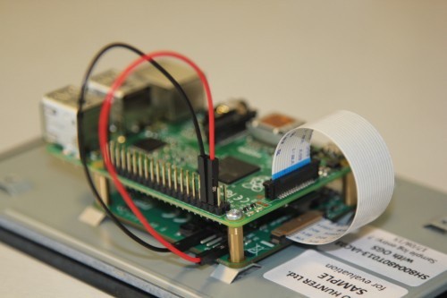
- Connect both, the data (ribbon cable) and power (red/black wires) from the Raspberry Pi to the display.
- Take extra care when attaching the ribbon cable to ensure it is the correct way around.
- The black and red power wires should be attached to the GND and 5V pins respectively.
![]()
As usual, before starting anything, you'll need to make sure that you're running the latest build of Raspbian. To do this, open a new Terminal window and type:
Sudo apt-get update
Follow the prompts, and then type:
Sudo apt-get upgrade
Your Raspberry Pi board should now be running the latest version of Raspbian, now enter the following to reboot:
Sudo reboot
There are three options for powering the display:
1) Separate power supply
Just add a separate uUSB power supply rated for at least 500mA, and plug into the display board where it says “PWR IN”.
2) USB link
Attach an official 2A Raspberry Pi power supply to the display board “PWR IN” connector, then attach a standard uUSB connector from the “PWR OUT” connector to the Raspberry Pi.
3) GPIO jumpers
Attach two of the supplied jumpers to connect 5V and GND from the Pi.
Screen Orientation and Video Display
LCD displays have an optimum viewing angle, and depending upon on how the screen is mounted it may be necessary to change the orientation of the display to give the best results. By default, the Raspberry Pi Touch Display and the Raspberry Pi are set up to work best when viewed from slightly above like on a desktop.
To set screen orientation when running the graphical desktop, select the Screen Configuration option from the Preferences menu. Right click on the DSI display rectangle in the layout editor, select Orientation then the required option.
To set the scree orientation when in the console mode, you will need to edit the kernel command line to pass the required orientation to the system.
Sudo nano/boot/cmdline.txt
To rotate by 90 degrees clockwise, add the following to the cmdline, making sure everything is on the same line, do not add any carriage returns. Possible...
Read more -
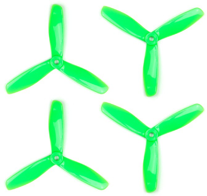
Drone Propellers
06/12/2020 at 06:12 • 0 commentsDrone flying has become popular among many people. People always like to fly their drones as high as possible or as fast as possible. One of the important components that keeps the drone in the air is the drone propellers. Confused? Well, They are a key component that keeps your drone in the air, they have the most direct impact on how your drone flies.
![]()
Today In this guide you will get to know what exactly a drone propeller is and what all factors should be kept in mind while buying a drone propeller.
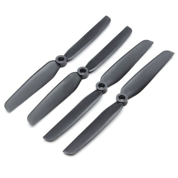
What is a Propeller?
A drone propeller is like a wing of the drone where the propellers create the airflow that lifts your drone into the air. Drone propellers come in many different shapes and sizes – they all serve the same overall purpose, but the flight characteristics of each can be dramatically different. When the propeller rotates it creates a low air pressure underneath it, resulting in lifting of the drone. The angle of the propellers are such that they drive the air downward.
![]()
The basic concept of a fixed blade propeller is that the faster the motor runs, the faster your propeller spins and more lift is created. Basically, more power = more speed.
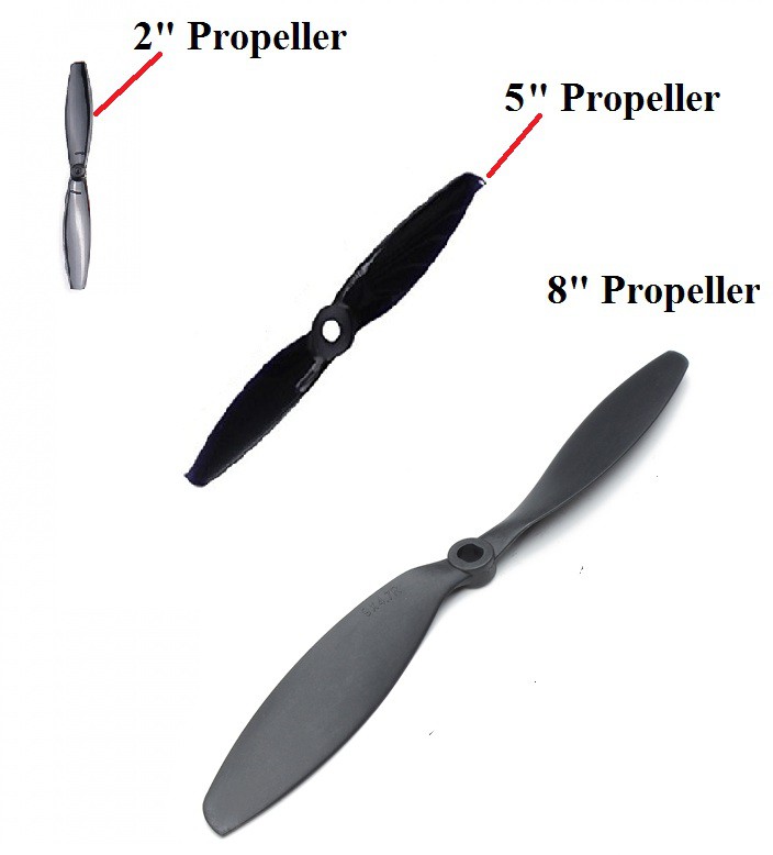
Size of the Propeller
Size is one of the first thing to consider when looking for a propeller for your drone. Propeller size is directly linked to thrust, responsiveness and the amount of ‘grip’ the multirotor will have in the air. When you have a drone propeller with small size then it is much easier to control overall speed of your device during flights as it reacts faster to the inputs and require less power to change their speed. This facility is not available with larger propellers.
![]()
A larger propeller sweeps through more air and therefore takes more energy to get spinning and will respond slower to inputs from the motors and consume more power. But the benefits of a larger propeller are increased thrust, and because it is working over a larger area, it will have a better ‘hold/grip’ in the air and more authority when making direction changes. Also they take a longer time to fall which can be frustrating at times when you want to instantly change the altitude of your drone or get under any branch or shelter.
Thus the important thing is that the size of the propeller must match with the rest of the components of your drone. For example, putting 3”props on a motor designed for 5”propellers will result in extremely high RPM and power draw and will create very little thrust. Likewise, putting large props on a small motor will likely be too much for the motor to spin, this will create very little thrust, lots of heat and excessive current draw. Extreme mismatches can damage motors and ESC’s.
In case you want to fly your drones with additional payload like a camera or a gimbal then it is advisable to buy a larger prop with slower turning motor unit.
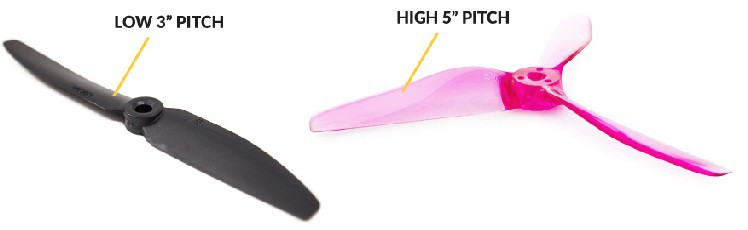
Drone Propeller Pitch
Pitch can be defined as total distance travelled by your drone with single rotation of propeller. For example, in case if we take 8x3 value then it means overall length is 8 whereas pitch is 3. Generally, propellers that offer lower pitches are able to produce more torque hence their motor naturally works with lesser current. High pitch will usually result in more overall thrust and top end speed, but less low-end torque. A high pitch propeller will respond to inputs slowly, use more power and will only be efficient when the multirotor is moving quickly.
![]()
Determining the pitch of the propeller for your specific application should match with the rest of your components. If you have chosen large powerful motors and plan to fly fast in large open areas then a high pitch propeller will be suitable, if you have smaller motors or are planning to use the multirotor in more confined spaces and make lots of direction changes then a lower pitch propeller will be suitable as it will be more responsive and...
Read more -
How to choose Radio Transmitter and Receiver
06/10/2020 at 14:11 • 0 commentsDrone Transmitter and receiver is one of the crucial components while building a drone.
It should be one of the first components that should be bought. It can be confusing as to which ones to buy. Also it is okay to spend a bit more on a good quality Radio Transmitter and Receiver as it will follow for many years to come.
This guide explains the basics of Radio transmitter and Receiver and what all parameters should be kept in mind while buying one.
![]()
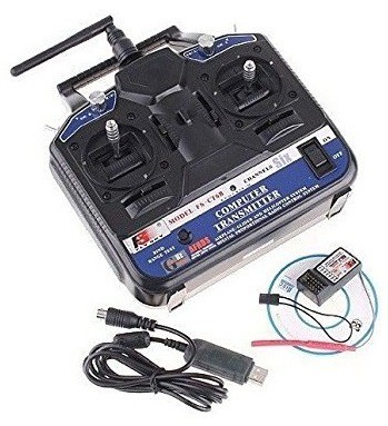
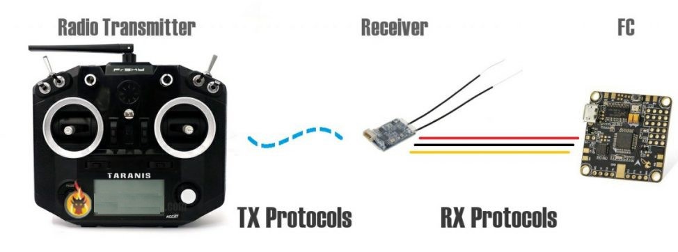
What are Drone Transmitter and Receivers?
Drone Transmitter is an electronic device that uses radio signals to transmit commands wirelessly via a radio frequency over to the Radio Receiver, which is connected to the drone being remotely controlled. In other words, it’s the device that translates pilot’s commands into movement of the drone.
![]()
Radio Frequency
A drone transmitter uses many frequencies like: 27MHz, 72MHz, 433MHz, 900MHz, 1.3GHz and 2.4Ghz, 433Mhz, 900Mhz and 1.3GHz. Most transmitters work on 2.4GHz.
It’s become the standard for radio control after new protocols were created that introduced frequency hopping technology. It basically looks for available channel automatically to avoid interfering with other pilots, allowing multiple pilots flying at the same time.
A Receiver must be compatible with the Radio Transmitter which in most cases means that the same brand of Rx and Tx need to be purchased in order to establish a communication. There are however radio receivers that may work with the same protocol but are not from the same brand.
Frequencies must also be the same on both Rx and Tx. For instance; a 2.4GHz Transmitter can only work with 2.4GHz Radio Receiver.
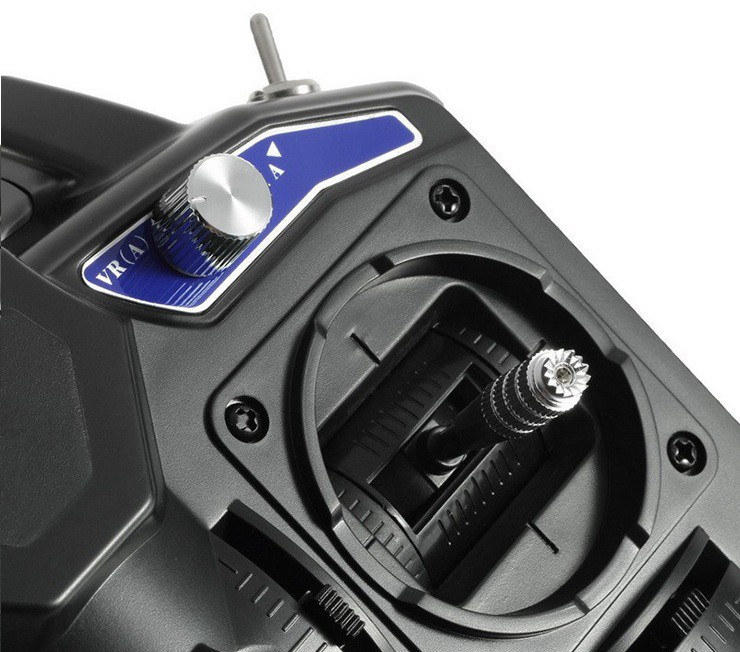
Gimbals
Gimbals are the sticks that translate a pilots input into the digital data transmitted to the radio receiver. Gimbals quality is one of the most important parameters while flying a drone. It can affect the handling when flying a drone, and the smoothness of your control. It can be one of the factors that decide how good you can fly a drone.
![]()
There are two types of gimbals commonly used
- Hall Effect Gimbal (digital)
- Potentiometer type Gimbal (analogue)
Hall Effect gimbals use hall sensors with magnets to capture the stick position values and is therefore more resistant to wear. These gimbals are also more precise.
Potentiometer type gimbals uses a brush to capture the value of stick inputs and is therefore prone to wear out much quicker.
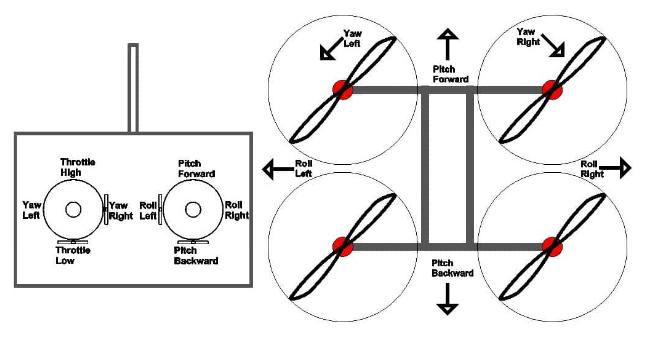
Channels
A Drone Radio Transmitter transmits commands via channels. Each channel is an individual action being sent to the aircraft. The basic channels are given below:-
![]()
- Roll. Moves your drone left or right in the air, literally “rolling” your drone.
- Pitch. Tilts your drone forward or backward.
- Yaw. Rotates your drone clockwise or counterclockwise, allowing you to make circles or patterns in the air.
- Throttle. Controls the amount of power sent to your drone, which makes the drone go faster or slower. It is recommended to have 1 or 2 extra channels so as to switch between modes. The number of channels you can use is also limited by the receiver protocol (the connection between receiver and flight controller).
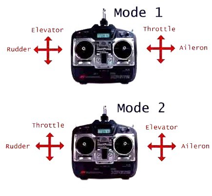
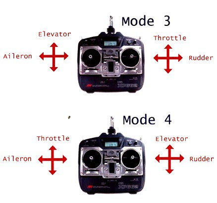
Modes
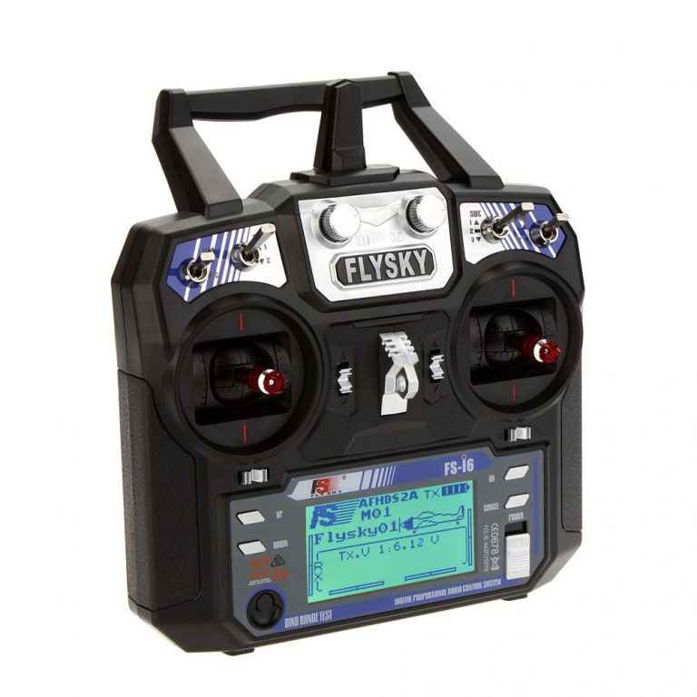
When purchasing an FPV Drone Radio Transmitter, you need to determine which “Mode” you would prefer to use when flying.
The mode determines aircraft movement assigned to a certain stick movement. There are 4 transmitter modes with Mode 2 being the most popular and is usually set as the default mode on most radios.
![]()
![]()
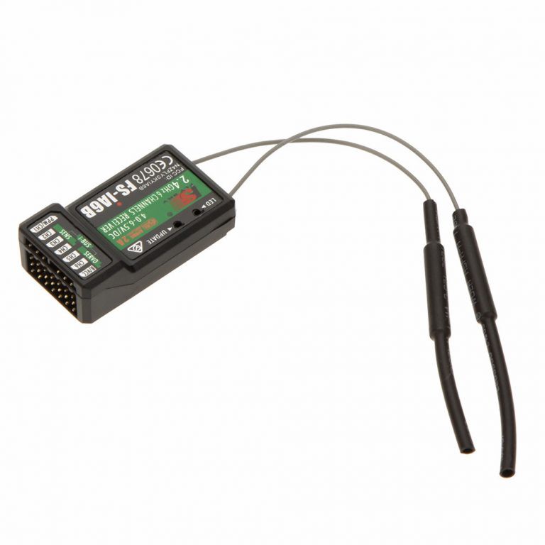
Radio Receivers
A Radio Receiver is the device capable of receiving commands from the Radio Transmitter, interpreting the signal via the flight controller where those commands are converted into specific actions controlling the aircraft.
![]()
A Receiver must be compatible with the Radio Transmitter which in most cases means that the same brand of Rx and Tx need to be purchased in order to establish a communication....
Read more -
How does a GPS Module Work
06/04/2020 at 12:17 • 0 commentsGPS is everywhere! You have probably used and benefitted from GPS. They are found in most of the smartphones, many new automobiles and now even in smart watches. It helps you to get where you want to go. These tiny devices can give your position and time simultaneously almost anywhere on the planet.
But what is GPS? In this guide we will give an insight of what is GPS, how it works and what are the applications of a GPS module.
What is GPS
GPS (Global Positioning System) is a satellite-based navigation system. It provides time and location-based information to a GPS receiver, located anywhere on or near the earth surface. GPS works in all weather conditions.
The satellite system consists of a constellation of 24 satellites in six Earth-centered orbital planes, each with four satellites, orbiting at 13,000 miles (20,000 km) above Earth and traveling at a speed of 8,700 mph (14,000 km/h).
While we only need three satellites to produce a location on earth’s surface, a fourth satellite is often used to validate the information from the other three.The GPS modules have become small over the years. These modules have tiny processors and antenna that receive data sent by the satellites and compute your position and time.
Working of GPS
GPS works through a technique called trilateration. Trilateration is the process of determining your position based on the intersection of spheres. When a receiver receives a signal from one of the satellite, it calculates its distance from the satellite considering a 3-D sphere with the satellite located at the center of the sphere. Once the receiver does the same with 3 other GPS satellites, the receiver then proceeds to find the intersection point of the 3 spheres to calculate it’s location. Used to calculate location, velocity and elevation, trilateration collects signals from satellites to output location information.
The GPS module receives a timestamp from each of the visible satellites, along with data on where in the sky each one is located (among other pieces of data). From this information, the GPS receiver now knows the distance to each satellite in view. If the GPS receiver’s antenna can see at least 4 satellites, it can accurately calculate its position and time.
A single satellite broadcasts a microwave signal which is picked up by a GPS device and used to calculate the distance from the GPS device to the satellite. Since a GPS device only gives information about the distance from a satellite, a single satellite cannot provide much location information. Satellites do not give off information about angles, so the location of a GPS device could be anywhere on a sphere’s surface area.
When a satellite sends a signal, it creates a circle with a radius measured from the GPS device to the satellite.
When we add a second satellite, it creates a second circle, and the location is narrowed down to one of two points where the circles intersect.
With a third satellite, the device’s location can finally be determined, as the device is at the intersection of all three circles.Applications of GPS
GPS is a powerful and dependable tool for businesses and organizations in many different industries. Surveyors, scientists, pilots, boat captains, first responders, and workers in mining and agriculture, are just some of the people who use GPS on a daily basis for work. They use GPS information for preparing accurate surveys and maps, taking precise time measurements, tracking position or location, and for navigation. GPS works at all times and in almost all weather conditions. There are main uses of GPS:
- Location - Determining a position.
- Navigation - Getting from one location to another.
- Tracking - Monitoring object or personal movement.
- Mapping - Creating maps of the world.
Parameters for Selecting the Right GPS Module
1. GPS Pulse Accuracy
This is the accuracy of 1Hz pulse received...
Read more -
What is Boost Convertor
06/03/2020 at 11:04 • 0 commentsHave you ever wondered how high voltage is obtained in Hybrid Electric Vehicles and Lighting system? Also a there have been a lot of situations where we need a higher voltage than our power supplies can provide. We need 12 volts, but have only a 9 volt battery. Or maybe we have a 3.3V supply when our chip needs 5V. Enter Boost Convertors.
It is a simple converter which is used to convert the DC voltage from lower level to higher level. Boost converters is also called a step up converter due to its function. In this guide we will see what is a Boost Convertor, how it works and the applications of it.
Boost Convertor
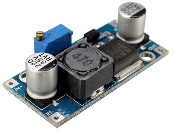
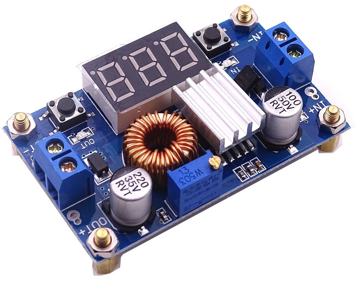
A boost converter (step-up converter) is a DC-to-DC power converter that steps up voltage from its input (supply) to its output (load). It is a class of switched-mode power supply containing at least two semiconductors and at least one energy storage element: a capacitor, inductor, or the two in combination. To reduce voltage ripple, filters made of capacitors are normally added to such a converter's output and input.
![]()
Power for the boost converter can come from any suitable DC source, such as batteries, solar panels, rectifiers, and DC generators. A boost converter is a DC to DC converter with an output voltage greater than the source voltage. A boost converter is sometimes called a step-up converter since it "steps up" the source voltage.
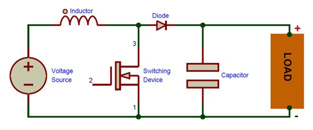
Working of Boost Convertor
The main working principle of boost converter is that the inductor in the input circuit resists sudden variations in input current. When switch is OFF the inductor stores energy in the form of magnetic energy and discharges it when switch is closed. The capacitor in the output circuit is assumed large enough that the time constant of RC circuit in the output stage is high.
![]()
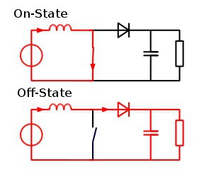
When the switch is closed, current flows through the inductor in the clockwise direction and the inductor stores some energy by generating a magnetic field. Polarity of the left side of the inductor is positive.
(b) When the switch is opened, current will be reduced as the impedance is higher. The magnetic field previously created will be destroyed to maintain the current towards the load. Thus the polarity will be reversed (meaning the left side of the inductor will become negative). As a result, two sources will be in series causing a higher voltage to charge the capacitor through the diode.
While the switch is opened, the capacitor in parallel with the load is charged to this combined voltage. When the switch is then closed and the right hand side is shorted out from the left hand side, the capacitor is therefore able to provide the voltage and energy to the load. During this time, the blocking diode prevents the capacitor from discharging through the switch. The switch must of course be opened again fast enough to prevent the capacitor from discharging too much.
![]()
- In the On-state, the switch is closed, resulting in an increase in the inductor current;
- In the Off-state, the switch is open and the only path offered to inductor current is through the flyback diode, the capacitor and the load. This results in transferring the energy accumulated during the On-state into the capacitor.
- The input current is the same as the inductor current as can be seen in figure 2. So it is not discontinuous as in the buck converter and the requirements on the input filter are relaxed compared to a buck converter.
When a boost converter operates in continuous mode, the current through the inductor never falls to zero. In the steady state, the DC voltage across the inductor must be zero so that after each cycle the inductor returns the same state, because voltage across the inductor is proportional to rate of change of current through it.
Applications of Boost Convertor
- They are used in regulated DC power supplies.
- They are used in regenerative braking of DC motors
- Low power boost converters...
-
What is Buck Convertor
06/03/2020 at 10:34 • 0 commentsWe have all come across situations where we need a change of voltage which is lower because the power supply is of a different voltage. Luckily for us it is possible to convert one DC voltage to another. Enter Buck Converters. These electronic modules can step down the voltage from its input to the output.
In this guide we will see what are Buck converters and how do these modules work.
Buck Convertors
A buck converter (step-down converter) is a DC-to-DC power converter which steps down voltage (while stepping up current) from its input (supply) to its output. It is a class of switched-mode power supply (SMPS) typically containing at least two and at least one energy storage element, a capacitor, inductor, or the two in combination. To reduce voltage ripple, filters made of capacitors are normally added to such a converter's output and input.
![]()
The basic operation of the buck converter has the current in an inductor controlled by two switches (usually a transistor and a diode). In the idealized converter, all the components are considered to be perfect. Specifically, the switch and the diode have zero voltage drop when on and zero current flow when off, and the inductor has zero series resistance.
Working of Buck Convertors
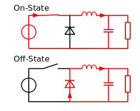
The conceptual model of the buck converter is best understood in terms of the relation between current and voltage of the inductor. Beginning with the switch open (off-state), the current in the circuit is zero. When the switch is first closed (on-state), the current will begin to increase, and the inductor will produce an opposing voltage across its terminals in response to the changing current. This voltage drop counteracts the voltage of the source and therefore reduces the net voltage across the load. Over time, the rate of change of current decreases, and the voltage across the inductor also then decreases, increasing the voltage at the load. During this time, the inductor stores energy in the form of a magnetic field.
![]()
If the switch is opened while the current is still changing, then there will always be a voltage drop across the inductor, so the net voltage at the load will always be less than the input voltage source. When the switch is opened again, the voltage source will be removed from the circuit, and the current will decrease. The decreasing current will produce a voltage drop across the inductor, and now the inductor becomes a Current Source. The stored energy in the inductor's magnetic field supports the current flow through the load.
This current, flowing while the input voltage source is disconnected, when concatenated with the current flowing during on-state, totals to current greater than the average input current. The "increase" in average current makes up for the reduction in voltage, and ideally preserves the power provided to the load. During the off-state, the inductor is discharging its stored energy into the rest of the circuit. If the switch is closed again before the inductor fully discharges, the voltage at the load will always be greater than zero.
Applications of Buck Convertors
- POL Convertors for Laptops and PCs - A Point-Of-Load Converter, or POL, is a non-isolated buck converter that’s capable of efficiently driving power to high current loads. Modern microprocessors run off very low voltage, typically 1.8V.
- Battery Chargers - typically, a charging port for a mobile device is a micro USB port. It accepts a regulated 5V. The charging circuits are on the inside of the mobile device, which is often a buck converter.
- Solar Chargers - A solar charger is often a buck converter with a microcontroller control. The microcontroller tells the buck converter to draw the maximum amount of power by varying the load current to charge the battery in the shortest time possible.
- Power Audio Amplifiers
The Step-Down convertors can be used in other applications like it can...
Read more -
How do ESCs Work
06/02/2020 at 12:01 • 0 commentsMuch like the drone’s propellers, motors, and the flight controller, another component that plays a huge role in allowing drone pilots to maneuver these flying machines with ease: the ESCs (Electronic Speed Controllers). These little circuit boards have been the center of attention of recent advances in drone technology.
ESC controls the speed of the motors in an FPV drone. The ESC receives throttle signals from the flight controller and drives the brushless motor at the desired speed. Using good quality ESC’s means you should have a reliable and smooth flight experience.
![]()
In this guide, you will get to know what exactly is an ESC, how do they work and the main considerations to keep in mind while buying an Esc for your drone.
What is an ESC?
An Electronic Speed Controller (ESC) is a device that regulates the power of an electric motor, allowing it to throttle from 0% to 100%. There are two styles of Electronic Speed Controller, Brushed and Brushless. Both work on the same principle.
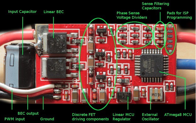
An ESC is made up of three key components. A BEC/voltage regulator, a Processer and the switching consisting of FETs.
The BEC/voltage regulator is a division of the ESC that will send a set amount of power back to your receiver to then power your servos. This also has a secondary function whereby if the battery that is driving the motor reaches its minimum voltage the BEC will reserve power for the flight critical controls, making sure the motor doesn't take all the power from the battery.
![]()
The processor is an integrated circuit that now days is completely contained in a single silicone semiconductor chip. Its job is to translate the information being given to it from the receiver in the model and switch the FETs to regulate the power to the motor. The FET is the component that is doing all the work in an ESC. It "sees" the full voltage and current of the battery and motor. A FET is essentially an electronic switch that chops up the flow of electricity that in turn throttles the motor.
Working of ESC
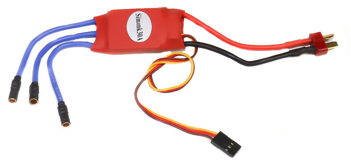
The ESCs are frequently used on RC models which are electrically powered, with the change most frequently used for brushless motors basically providing an electronically produced 3-phase electric power low voltage source of energy for the motor.
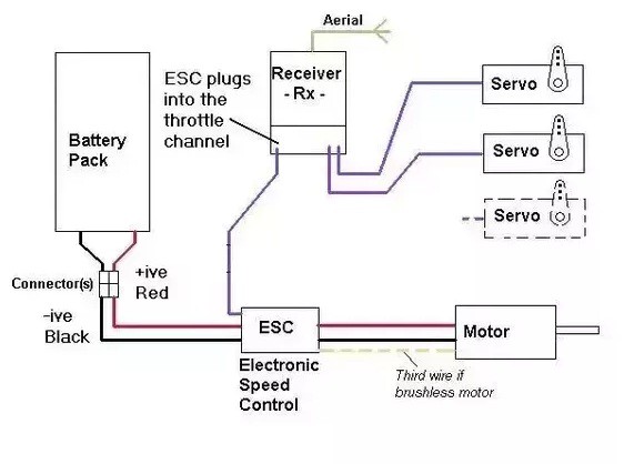
An electronic speed control will have 3- sets of wires. One wire will plug into the main battery of an airplane. The second wire will have a typical servo wire that plugs into the receiver’s throttle channel.
![]()
Firstly the pilot transmit the signal from radio transmitter and that signal is received by radio receiver which is fixed at the Drone and then further that signal is sent to the Flight controller board which generates an Appropriate signal which is forward to the Electronic Speed Controller The ESC takes the signal from the flight controller and power from the battery and makes the motor spin according to the strength of signal of the Electronic Speed Controller that it received from the flight controller.
Connection of ESCs
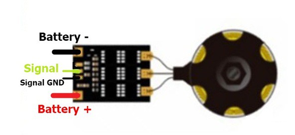
ESC is powered directly by LiPo battery, and motor speed is controlled by a signal from the flight controller.
The motors are connected to the ESC through 3 wires. The wire order doesn’t actually matter. If the motor spins the wrong direction, simply swap any two wires.
![]()
Factors to Keep in Mind while Buying an ESC
In selecting an ESC, it is important to think about the main considerations. The considerations for ESC choice include:
- Motor size: The size of the motor will greatly dictate the amount of amperage your ESC must be able to handle.
- Propeller: Choice of propeller will also dictate what amp rating your ESC should be. The pitch of the propeller will determine how much high amperage ESC you would want
- Battery: Will you be using a 3 cell battery, or a 4, 5 battery. ESCs are rated for amperage, along with battery cells.
Selecting the right ESC is important...
Read more -
How to Select Drone Frames
06/01/2020 at 15:14 • 0 commentsToday Drones have become a trending topic due to wide no. of applications. Everyone aspires to have their own drones and fly them. With new innovations in its components every now and then, the demand of drones is increasing day by day. But have you ever wondered what keeps a drone together and protected?
A Drone Frame is the one that holds the Drone together with all its components and acts like a suit of armor for all of the sensitive electrical components. . You have to be very precise while choosing it. They need to be designed strong but also lightweight. It is equally important and relative to choosing the best electronic components such as the Electronic Speed Controls (ESCs), propellers, arms, and motors.
You probably know that there are different types and configurations of drone frames. This guide will take you through some of the important things that you need to keep in mind while choosing a Frame for your drone.
![]()
Frame Design/Size
First you have to decide the Frame Design that you want. While purchasing a Drone Frame it is important to know the configuration that you want for your drone. It all depends on your preference and how many components that is the motors, batteries you intend to use in your drone.
All parts of drone will be hold on the frame, First you can decide as to which frame should take? Generally speaking, from 180 mm to 250 mm is most popular frames, more bigger one is from 280mm to 800mm even more.
Frame Material
The first thing on your mind should be the materials when picking the best frame. The materials play a significant role in determining the drone’s stability and efficient performance. Note that vibration is increasingly a nuisance in many drones, and if not managed well, it could lead to poor quality aerial images and possible damage to the electronic components.
Most frames are designed with carbon fibers because of its light weight properties. However, the downside of carbon fibers is radio signal interference. It is nonetheless a good material for your frame.
The frame needs to be stiff. The stiffness enables the frame to be stable and smooth enough without any detrimental bends in the sky. A smooth flight will yield smooth and stable videos and photographs. Moreover, the frame should be brittle, but not too brittle.
One of the most common materials for multi-rotor frames is carbon fiber.It is lightweight but expensive. A great many of its physical properties are perfectly suited to the hobby. The only catch is that carbon fiber is known to block radio signals, which is obviously not ideal for a hobby that depends on multiple transmissions. That means you have to exercise a bit of care in how you place antennas on your craft.
There are other materials also like wood, Metal, Plastic or Fiberglass from which you can build your own drone.
Battery Placement
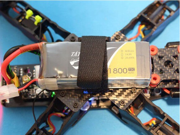
Battery placement is a very much a preference. The weight of the drone battery is quite a large proportion of the craft, so where you place it very much effects the handling. The ultimate aim is to get it as close to the center of gravity as possible. Ultimately you can put it in 2 places; on top or underneath.
Most free style frames have top mount batteries with the battery inline with the frame. This protects the battery in most crashes. However, it is not optimal for performance due to the weight being balanced above the center mass of the craft.
![]()
Placements of Other Important Components
The placement of some of your important components like motors, ESCs, antennas and Camera should be considered. For e.g. if there are mounting tabs in the drone frames for mounting Camera and other accessories. Your FPV Camera is what you use to see, so you need to make sure it is well placed. You need to be in a location where you can get a good clean line of sight. It is common to have some props in view especially on stretched x frames, but you don’t want to have it blocking...
Read more -
IR Infrared Obstacle Avoidance Sensor With Arduino
05/30/2020 at 06:20 • 0 commentsThere have been many innovations in technology which have changed the world. One of them is Infrared Technology. Now a days, an Infrared technology has a wide variety of wireless applications mostly in object sensing and remote controls.
Today we will talk about Infrared Obstacle Avoidance Sensor Module, its working and how to connect it with Arduino.
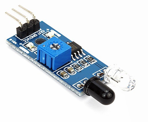
Infrared IR Sensor Obstacle Avoidance Sensor board is an inexpensive solution to avoidance detection for robotics, smart car and other electronic uses.
![]()
Infrared Obstacle Sensor Module has built in IR transmitter and IR receiver that sends out IR energy and looks for reflected IR energy to detect presence of any obstacle in front of the sensor module. The module has on board potentiometer that lets user adjust detection range. The sensor has very good and stable response even in ambient light or in complete darkness.
The Obstacle Avoidance Sensors usually come in two types – with 3 and 4 pins.
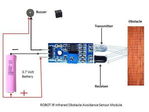
WORKING PRINCIPLE
The IR transmitter sends an infrared signal that, in case of a reflecting surface (e.g. white color), bounces off in some directions including that of the IR receiver that captures the signal detecting the object. When the surface is absorbent the IR signal isn’t reflected and the object cannot be detected by the sensor. This result would occur even if the object is absent.
![]()
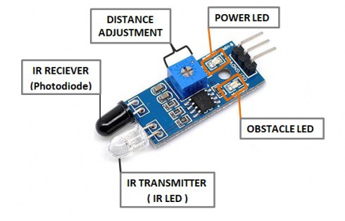
The module has 3 pins – Vcc, GND and the output. We also have 2 LEDs, one is for the power that is it turns ON when it is connected to the power. The other is for the obstacle detection.
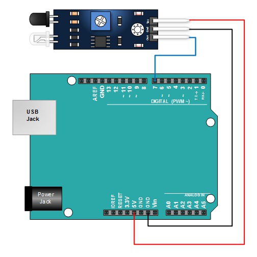
Connections
- Connect the Vcc of the Sensor Module to the Vcc of Arduino Board
- Connect GND of the sensor Module to the GND of the Arduino Board.
- Connect the output pin of the sensor module to pin 7 of the Arduino Board.
- When the Obstacle Avoidance Sensor detects an obstacle, the LED will be on. Otherwise it will be off.
![]()
Code
After above operations are completed, connect the Arduino board to your computer using the USB cable. The green power LED (labelled PWR) should go on.Open the Arduino IDE and choose corresponding board type and port type for you project. Then load up the following sketch onto your Arduino.
int LED = 13; // Use the onboard Uno LED
int isObstaclePin = 2; // This is our input pin
int isObstacle = HIGH; // HIGH MEANS NO OBSTACLE
void setup() {
pinMode(LED, OUTPUT);
pinMode(isObstaclePin, INPUT);
Serial.begin(9600);
}
void loop() {
isObstacle = digitalRead(isObstaclePin);
if (isObstacle == LOW)
{
Serial.println("OBSTACLE!!, OBSTACLE!!");
digitalWrite(LED, HIGH);
}
else
{
Serial.println("clear");
digitalWrite(LED, LOW);
}
delay(200);
}
A few seconds after the upload finishes, place a board in front of the Obstacle Avoidance Sensor, and the LED attached to pin 7 on the Arduino Uno board will light up, the on-board obstacle led will turn on. It will turn off when there is no obstacle.
At the same time, choose the corresponding port type for you arduino board and open the Serial Monitor of the Arduino IDE, make sure the baudrate is same as your code, move the obstacle in front of the Obstacle Avoidance Sensor, you will see the serial output as below:
![]()
![]()
Thus using an Arduino and an Obstacle Avoidance sensor for your Smart cars, robots etc. and make your respective project successful.
For getting an IR Infrared Obstacle Avoidance Sensor Click Here.
To explore more such exciting sensors Click Here
-
Top 10 Drone Frames in India
05/29/2020 at 06:16 • 0 commentsWith the Demand of Drones increasing day by day, the protection of drones has also become important.
Drone frame is one of the important component of a Drone. The structure that holds all the components together. One of the most important part of Drone is its frame because it supports motors and other electronics and prevents them from vibrations. You have to be very precise while making it. They need to be designed to be strong but also lightweight.
You probably know that there are different types and configurations of drone frames. This guide will take you through some of the best drone frames that will keep your drones safe and long-lived.
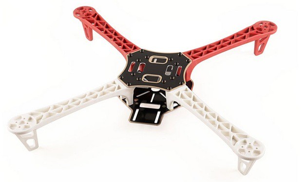
1. Q450 Quadcopter Frame
![]()
The Q450 Quadcopter Frame is very popular and mostly used Multirotor Frame by the hobbyists!!! This is 3rd version of Q450 Quadcopter Frame comes with stronger material over v1 and v2, so no more arm breakage at the motor mounts on a hard landing. The arms of the frame are colored as 2 red and 2 white which can guide you to fly in the right direction.
They are strong, light, and have a sensible configuration including a PCB(Printed Circuit Board) with which you can directly solder your ESC‘s to the Quadcopter. Thus, making the Quadcopter build fast and easy. Much lighter weight, higher strength Aerodynamic structure of this Q450 frame featuring PA66 arms with glass fiber integrated frame make it the first choice of our customer.
Price – 850Rs
For getting the Q450 Quadcopter Frame Click Here
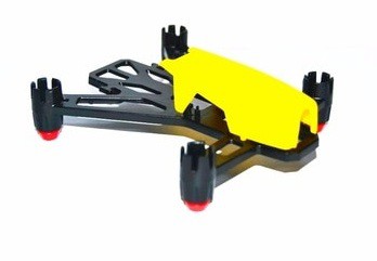
2. Q100 Brushed Quad-copter Frame
![]()
The Q100 is a mini-size smallest frame among the quadcopter frame class. The compact design with ABS plastic body has made them popular in FPV racing. This is ready-2-fly quadcopter frame requires only basic installation. You can enjoy the versatility of the Q100 racing drone by practicing your flying, racing, or aerial acrobatic drone skills either indoors or outside in tough environmental conditions.
The frame is designed in such a way that all the necessary component with a camera can be easily installed. It has the pre-reserved mounting hole for mini FPV camera. The frame has the wheelbase of 100mm and weighs around 12gm. The Q100 Mini Quadcopter Frame is lightweight, has excellent agility and less destructive inertia in a crash.
Price – 299Rs
For Getting Q100 Quadcopter Frame Click Here
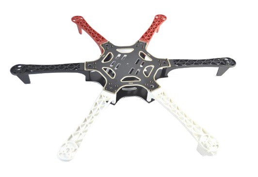
3. F550 Hexa-Copter Frame
![]()
This is Hexacopter Frame which employs 6 arms to get into the air. This frame is for a bigger drone where an extra amount of batteries, motors and accessories can fit in. This F550 Hexa-Copter Frame is made from Glass Fiber which makes it tough and durable. They have the arms of ultra-durable Polyamide-Nylon which are the stronger molded arms having a very good thickness so no more arm breakage at the motor mounts on a hard landing.
The arms have support ridges on them, which improves stability and provides faster forward flight. The frame has the wheelbase of 550mm and weighs around 620gm. It features mounting tabs at the front and rear end on the bottom plate of the mainframe for mounting cameras and other accessories.
Price – 1990Rs
For Getting F550 Hexa-copter Frame Click Here
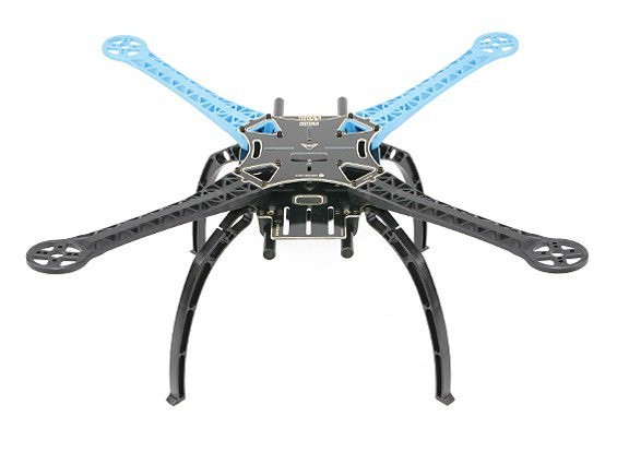
4. S500 Multi Rotor Air PCB Frame
![]()
The S500 Multi-Rotor Air PCB Frame serves as the upgradation of F450 Quadcopter Frame. It keeps everything that has made the F450 Quadcopter frame successful. The main great advantage of this frame is the arms have a slight upsweep, this gives the Quadcopter a dihedral effect which helps to make it very stable, especially when descending from altitude. The arms have a carbon fibre rod through the center for making the strongest arms we have seen to...
Read more -
Raspberry Pi 4 Model-B with 8 GB RAM
05/29/2020 at 06:00 • 0 comments![]()
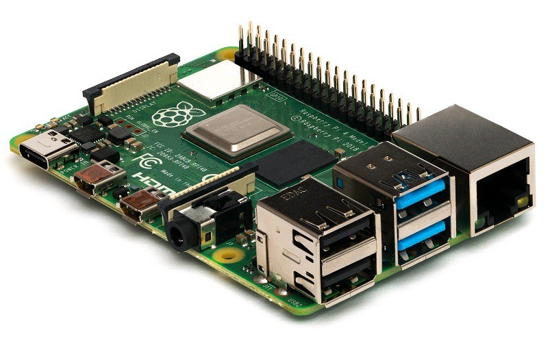
Raspberry Pi Foundation came up with the next iteration of Raspberry Pi 4 Model-B single-board computer. The Raspberry Pi 4 Model-B with 8GB RAM. . It offers ground-breaking increases in processor speed, multimedia performance, memory; and connectivity compared to the prior-generation Raspberry Pi 3 Model B+ while retaining backwards compatibility and similar power consumption. For the end-user, Raspberry Pi 4 Model B provides desktop performance comparable to entry-level x86 PC systems.
- Processor: Broadcom BCM2711, quad-Core Cortex-A72(ARM V8)64-BIT SoC @1.5GHz
- RAM Memory: 8GB LPDDR4 SDRAM
- Operating Power: 5 V 3A DC via GPIO Header,
- Clock speed: 1.5GHz
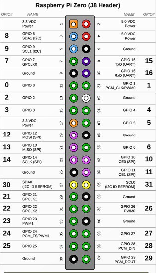
- GPIO: Standard 40-pin GPIO Header
- Micro-SD Card Slot: Yes (FAT32 format), support maximum 32G Micro SD Card Memory Features.
- Connectivity: 2 x USB 2.0 Ports.
5 V 3A DC via USB Type-C Connector
2 x USB 3.0 Ports.
2.4GHz & 5.0 GHz IEEE 802.11b/g/n/ac wireless LAN. BLE gigabit Ethernet bluetooth 5.0.
To get Raspberry Pi 4 Model-B With 8 GB RAM Click Here
For more Information on Raspberry Pi 4 Model B 8GB RAM Click Here
-
Raspberry Pi Zero W Overview and Official Case
05/26/2020 at 14:12 • 0 commentsEver dreamt of your own single board computer? Well, Raspberry Pi makes it easier for you to build your own single board computer. The Raspberry Pi is a low cost, credit-card sized computer that plugs into a computer monitor or TV, and uses a standard keyboard and mouse. It is a capable little device that enables people of all ages to explore computing, and to learn how to program in languages like Scratch and Python.
The developer’s basic idea was to provide computing to all the people making computers cheap and accessible to everyone so that everyone can learn programming without having to spend a lot of money on PC. It has a potential to do everything which you expect from a normal desktop computer like browsing, watching HD videos, making sheets, playing games, etc.
![]()
There have been many great boards from Raspberry Pi like Raspberry Pi 4, 3B+ and many more. The Raspberry Pi 4 4GB model is the best board by Raspberry Pi to date with the latest technology and interfaces available which easily makes it the most powerful board in the Raspberry Pi family. Every Techie would like to have this board but the hiccup that they face is the cost of the board is a tad too high. Thus, to solve this problem Raspberry Pi came up with Raspberry Pi Zero.
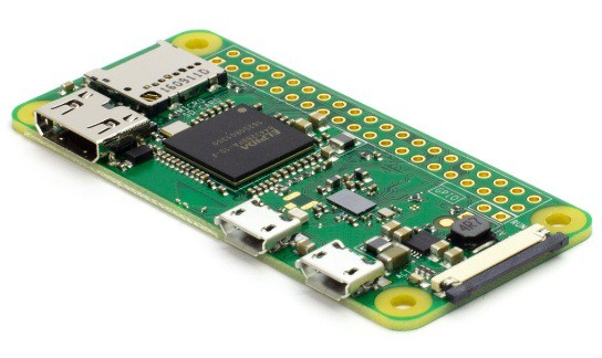
The Raspberry Pi Zero is a fantastic, miniature version of the Raspberry Pi that shrinks the board down to about the size of a stick of gum, but one problem with it is the lack of wireless features. The Raspberry Pi Zero W is a new version that packs in Bluetooth and Wi-Fi for a low price. The new Raspberry Pi Zero Woffers all the benefits of the Pi Zero v1.3, but with one big difference – built-in WiFi and Bluetooth for a low price!
The difference between the original and v1.3 was easy to see because the camera connector was added to one end of the board. The difference in the Zero W is more subtle. You can see pretty easily that a couple of new components have been added in the same area where the camera connector is located.
![]()
This is the slimmest, most pared down Raspberry Pi to date. It's kind of like the little cousin to the Pi 2 - with just a micro SD card slot, a mini HDMI port, two micro USB ports (one for power, one for USB), and 512MB of RAM. It has a single-core 1 GHz processor chip, similar to the Pi A+ and B+. The best part about all this is that the Pi Zero W keeps the same shape, connectors, and mounting holes as the Pi Zero v1.3. 99% of cases and accessories will still be fully compatible with both the Pi Zero W and v1.3.
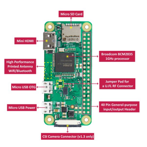
Here’s a breakdown of the full specs on the Raspberry Pi Zero W:
- 1GHz, Single-core CPU
- 512MB RAM
- Mini HDMI and USB On-The-Go ports
- Micro USB power
- HAT-compatible 40-pin header
- Composite video and reset headers
- CSI camera connector
- 802.11n wireless LAN
- Bluetooth 4.0
Connecting to WiFi
Next, let's connect the Pi Zero W to the internet. If you have a Pi Zero, you will need to add a Wifi dongle to your board's USB port (you may need a USB hub at this point). The Pi Zero W has built in WiFi, so you will not need any external WiFi dongles.
![]()
To enable WiFi on your Pi, look at the upper left corner of the Desktop, and left click the WiFi icon. You should see a list of available networks. Select the one you want. If it is a secured network, it will prompt you for a password. Enter the network password, and press OK. Give it a few seconds, and you should be connected. The WiFi symbol on the Desktop will change its appearance once connected. If you setup WiFi in Noobs, this information will already be saved. Adding WiFi isn't strictly necessary, but you will need internet access if you plan on doing updates.
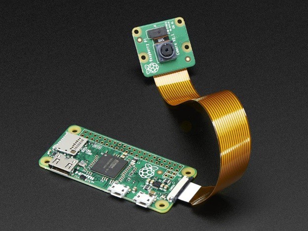
Camera Interfacing
The key feature of the of the Raspberry Pi Zero W V1.3 was to support camera serial interface (CSI connector) which used to be equipped on high end Raspberry Pi. Thus, Pi Zero w began to be able to connect with...
Read more -
Raspberry Pi Zero W V1.3 Development Board
05/22/2020 at 13:37 • 0 commentsEver dreamt of your own single board computer? Well, Raspberry Pi makes it easier for you to build your own single board computer. The Raspberry Pi is a single board computer which plugs into monitor, TV or directly connect wireless with laptop and is a low cost device. You can use a standard USB keyboard and mouse to operate it.
The developer’s basic idea was to provide computing to all the people making computers cheap and accessible to everyone so that everyone can learn programming without having to spend a lot of money on PC. It has a potential to do everything which you expect from a normal desktop computer like browsing, watching HD videos, making sheets, playing games, etc.
Some of the Raspberry Pi boards like Raspberry Pi 4 models prove to be costly for many people. Don’t worry! The Raspberry Pi Foundation recently launched the Raspberry Pi Zero W, an improved version of the original Raspberry Pi Zero that adds built-in Wi-Fi and Bluetooth. The Pi Zero W is a small-scale version of the popular Raspberry Pi (RPi) Linux single board computer (SBC). You can build the same awesome Raspberry Pi projects with a Pi Zero W.
Through this blog you will get hardware overview of the board and how to install the software of Raspberry Pi. Also, you will get to know about some additional features of the Raspberry Pi Zero W like the Camera Serial Interface (CSI) and many more.
![]()
Hardware Overview
It is a fully working 32-bit computer with a 1 GHz ARMv6 single core microprocessor (ARM1176), a VideoCore 4 GPU, and 512 MB of memory. The GPU is capable of driving a full HD display at 60 fps. You also get access to the 40 General Purpose Input and Output (GPIO) ports, however the header is unpopulated, meaning there are no pins.
![]()
The Zero W is meant to be bare bones, cheap, and versatile, so hobbyists and professionals alike can make anything they’d like. Like the original Pi Zero, the System-on-a-Chip (SoC) is near the middle of the board, while the various ports are found towards the bottom. There is a mini-HDMI port for the display as well as two micro-USB ports – one for power and the other for data. To use the micro-USB port to connect peripherals like a keyboard or mouse you will need a micro-USB B male to USB A female adapter.
Software
The operating system of choice for all Raspberry Pi boards is Linux, specifically the Debian based Raspbian. Installing Raspbian is a breeze. You need to download the New Out Of the Box Software (NOOBS) zip archive and extract it onto a blank microSD card. Boot the Pi Zero W from the card and follow the on screen instructions. Once complete the Zero will reboot into the Raspbian desktop environment.
![]()
When the desktop appears you will probably want to configure the networking. Click on the network icon (near the clock at the top-right of the screen) and you will see a list of all available wireless networks. Select the one you want and enter the password. If you right-click the network icon and choose the Wireless & Wired Network Settings option from the pop-up menu, you can manually enter a static IP address.
While you are in Raspberry Pi Configuration, you can also set the hostname of your Pi Zero W and also configure the auto login options. Under the Interfaces tab you should also enable SSH login which will allow you to connect to your Pi Zero W over SSH.
With the Wi-Fi network configured and SSH enabled, you are now ready to disconnect the keyboard, mouse and monitor, and reboot to access your Zero W remotely.
Camera Interfacing
The key feature of the of the Raspberry Pi Zero W V1.3 was to support camera serial interface (CSI connector) which used to be equipped on high end Raspberry Pi. Thus, Pi Zero w began to be able to connect with cameras.
![]()
Indeed, numerous Raspberry Pi users choose to add Raspberry Pi cameras...
Read more -
Transmitter and Receiver for Drones
05/21/2020 at 12:59 • 0 commentsFlySky FS-i6 2.4G 6CH PPM RC Transmitter With FS-iA6B Receiver
A lot of people are building interest in flying a drone and knowing its ocean of applications that it can be used for. Drones are one of the fastest growing technology industries in the world with new innovations in its components every now and then. With its varied application the demand of drone is increasing day by day. Maybe you want to get in on the future of aerial photography. Maybe you’re looking for a fun and futuristic toy for your kids.
Drones can’t fly themselves! Well they can but the whole point of flying a drone is actually controlling it. Drone controllers are everywhere in the drone world, but have you ever stopped to think about how they actually work? , which controller to choose and which site is the best to buy a drone controller.
![]()
In this blog we will look at all of these things starting with the basics of drone controllers, looking at how drone remote controllers work and the different features they give drone pilots.
Drone Transmitter
A Drone Radio Transmitter is an electronic device that uses radio signals to transmit commands wirelessly via a set radio frequency over to the Radio Receiver, which is connected to the drone being remotely controlled. In other words, it’s the device that translates pilot’s commands into movement of the multirotor. A FPV Drone Radio Transmitter transmits commands via channels. Each channel is an individual action being sent to the aircraft.
- Roll. Moves your drone left or right in the air, literally “rolling” your drone.
- Pitch. Tilts your drone forward or backward.
- Yaw. Rotates your drone clockwise or counterclockwise, allowing you to make circles or patterns in the air.
- Throttle. Controls the amount of power sent to your drone, which makes the drone go faster or slower.
![]()
Frequency of the Transmitter
An FPV Drone Radio Transmitter commonly use the following frequencies: 27MHz, 72MHz, 433MHz, 900MHz, 1.3GHz and 2.4Ghz, 433Mhz, 900Mhz and 1.3GHz are typically used in long range FPV and RC systems.
OpenTX is an open source custom firmware made for RC radio transmitters, compatible with the following radios:
- FrSky Taranis X9D, Q7X, X9E
- FrSky Horus X10, X12
- Turnigy 9X
- FlySky 9X
OpenTX is a highly configurable system offering plenty options for all types of RC models. It is created by FPV pilots with pilots in mind.
Wi-Fi and Bluetooth have made it possible for drone manufacturers to create device controls that run on smartphone or tablet. Not just a smartphone version of your RC transmitter, but high-tech controls.
Radio Receivers
A Radio Receiver is the device capable of receiving commands from the Radio Transmitter, interpreting the signal via the flight controller where those commands are converted into specific actions controlling the aircraft.
![]()
Radio Receivers can have the following features:
- Telemetry (sending data back to transmitter)
- Redundancy function (two receivers connected together, if one loses connection, second one takes over)
- Easy removable antennas (more convenient with connectors if antenna is to be replaced)
- Possibility of firmware upgrades (for bug fixes)
Telemetry is the data transmitted from the Radio Receiver back to the Radio Transmitter.
It usually contain a variety information, depending on the type of radio and flight controller. The most crucial pieces of information are battery voltage reading, current draw and “RSSI”
Radio communication protocols can split into two groups:
- TX Protocols between Radio Transmitter and Radio Receiver.
- RX Protocols between Radio Receiver and Flight Controller
TX Protocols are in most cases specific to brands:
- FrSky: D8, D16, LR12
- Spektrum: DSM, DSM2, DSMX
- FlySky: AFHDS, AFHDS 2A
- Futaba: FASST
- Hitec: A-FHSS
- Devo: Hi-Sky
However, there are also brand specific ones:
- TBS: CRSF Crossfire
- Graupner: SUMD,...
-
Soil Moisture Sensor for Arduino
05/21/2020 at 08:16 • 0 commentsEver thought of a home automated watering system in your own garden? A garden that automatically gives the measurement of the moisture content of the soil, waters plants automatically and give you the readings of the wetness of the soil, then you will definitely need a Soil Moisture Sensor. With the help of Arduino and soil sensor you can turn your ordinary garden into a smart which waters the plants automatically and keeps them and the soil in good conditions.
Through this blog we will look at how exactly Soil Moisture Sensor works and how to interface it with Arduino.
![]()
Working of Soil Moisture Sensor
The soil moisture sensor consists of two probes that measures the volume of water in the soil. The two probes allow the electric current to pass through the soil and, according to its resistance, measures the moisture level of the soil.
Most soil moisture sensors are designed to estimate soil volumetric water content based on the dielectric constant of the soil. The dielectric constant can be thought of as the soil's ability to transmit electricity. The dielectric constant of soil increases as the water content of the soil increases. This response is due to the fact that the dielectric constant of water is much larger than the other soil components, including air. Thus, measurement of the dielectric constant gives a predictable estimation of water content.
![]()
When there is more water, the soil conducts more electricity, which means that the resistance will be less. So the moisture level will be higher. Dry soil reduces conductivity. So, when there is less water, the soil conducts less electricity, which means it has more resistance. So the moisture level will be lower.
There are many different types of Soil Moisture Sensors but their working principle is the same. All of these sensors have at least three pins: VCC, GND, and AO. The AO pin changes according to the amount of moisture in the soil and increases as there is more water in the soil.
Connections
- Connect the two pins from the Sensor to the two pins on the Amplifier circuit via hook up wires.
- Connect the Vcc from the Amplifier to the 3.3V pin on the Arduino and the Gnd pin to the Gnd pin on the Arduino.
- Now connect the Analog Data Pin to the A0 pin on the Arduino.
![]()
Code
#define SensorPin A0
float sensorValue = 0;
void setup() {
Serial.begin(9600);
}
void loop() {
for (int i = 0; i <= 100; i++)
{
sensorValue = sensorValue + analogRead(SensorPin);
delay(1);
}
sensorValue = sensorValue/100.0;
Serial.println(sensorValue);
delay(30);
}
Write the above code on the Arduino software and verify/debug it. For each soil moisture measurement, we took an average of 100 sensor data to make the data more stable and accurate. You can modify the code as per your requirements. After verifying the code, upload it on the Arduino board.
You can check the working of the sensor when you dip the sensor leads in a water filled soil and in a dry one. You can keep these values as reference for future use. Also, please note that the sensor may get oxidized in the soil after 10-12 months and lose its accuracy. Thus, you will have to replace the sensor every year.
Thus using an Arduino and a Soil Moisture Sensor you can make your garden smart and a home automated watering system. If you want a Soil Moisture Sensor along with some of its accessories at the best price click on the link below. For more interesting sensors do check out our site Robu.in, the link is given below.
akanzler007's pages
I am a happy DIY geek. Loves to design and fly drone. Also, inspired by the Raspberry Pi Board.