 Hexabitz
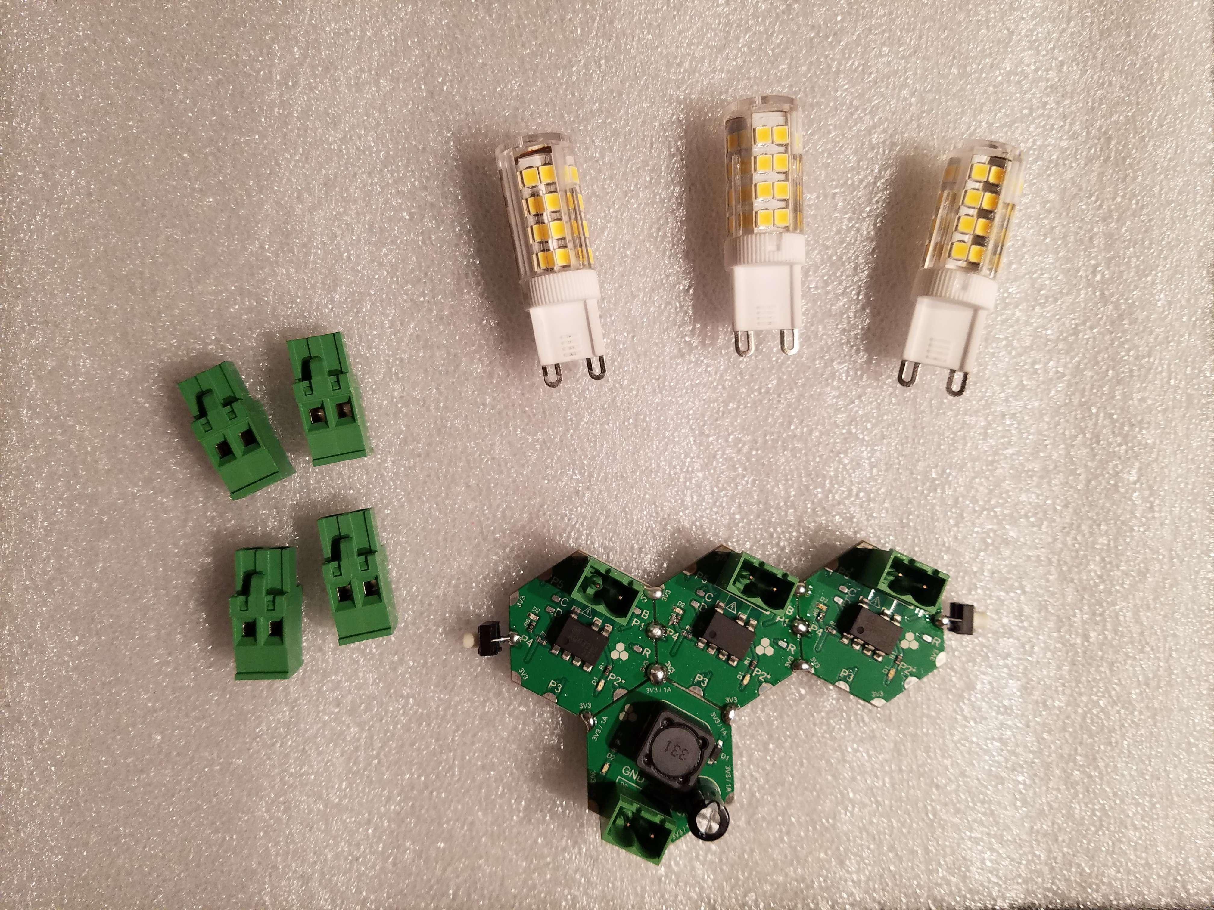
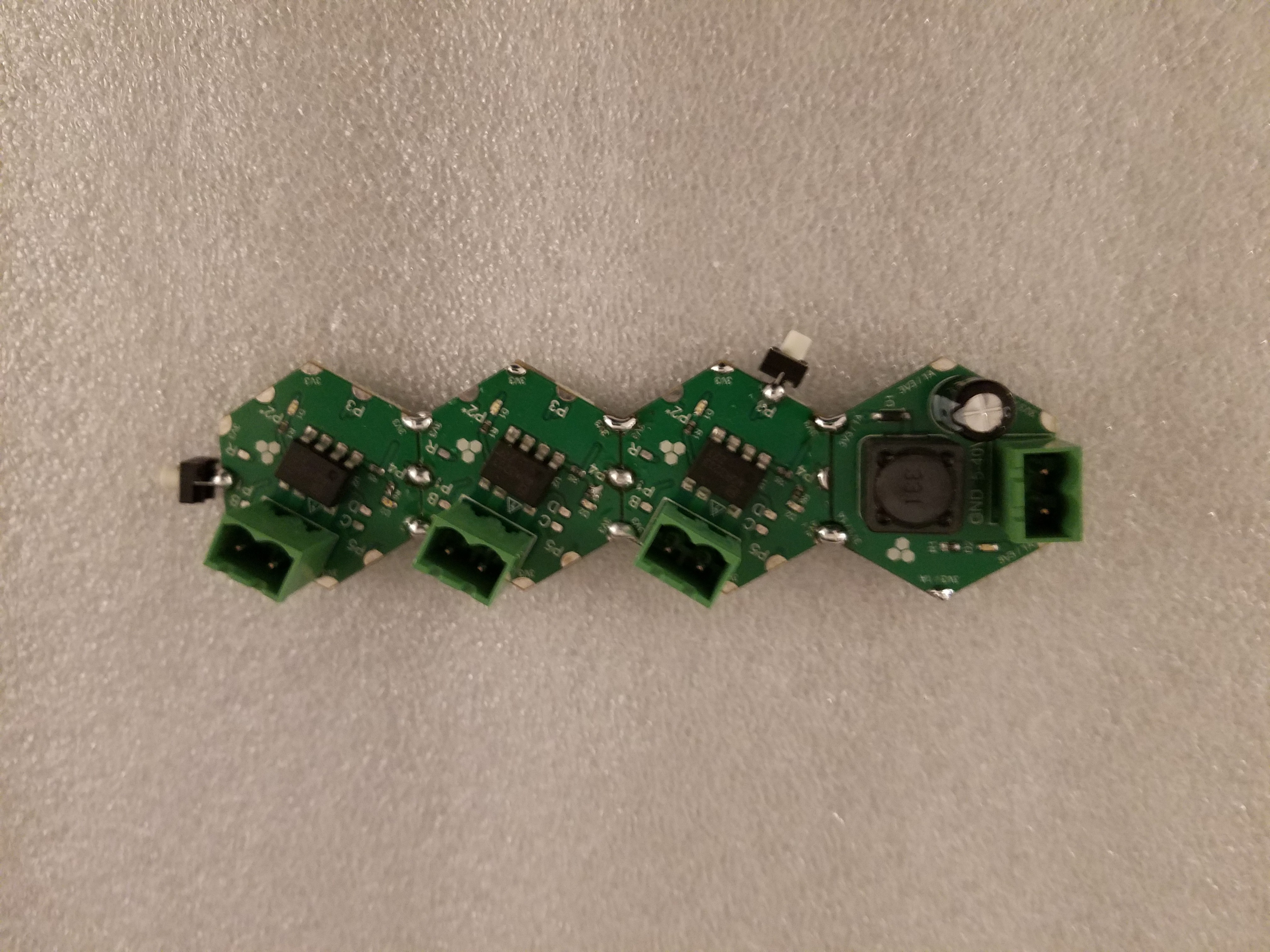
We built a smaller array of three relay modules (H09R00) and one DC-DC power module (H03R00 ) to control actual AC loads. This is a simple software example to test SSR functionality:
- Button 1 (connected to module 1) broadcasts a Toggle Message to all modules so that they toggle their output state. Note that the orange LED is directly connected to relay output. So whenever the relay is ON (switch closed), the orange LED is ON.
- Button 3 (module 3) toggles between modules starting with 1 then 2 and then 3. Combining these two button actions you can create interesting patterns. Also pressing button 1 for 1 second turns off all relays.
This example is shown in the following three videos:
- One without any load (this is the best way to develop and debug the software. Once you're satisfied with results you can easily disconnect programmer and plug in the green connectors and power the H03R00 module)
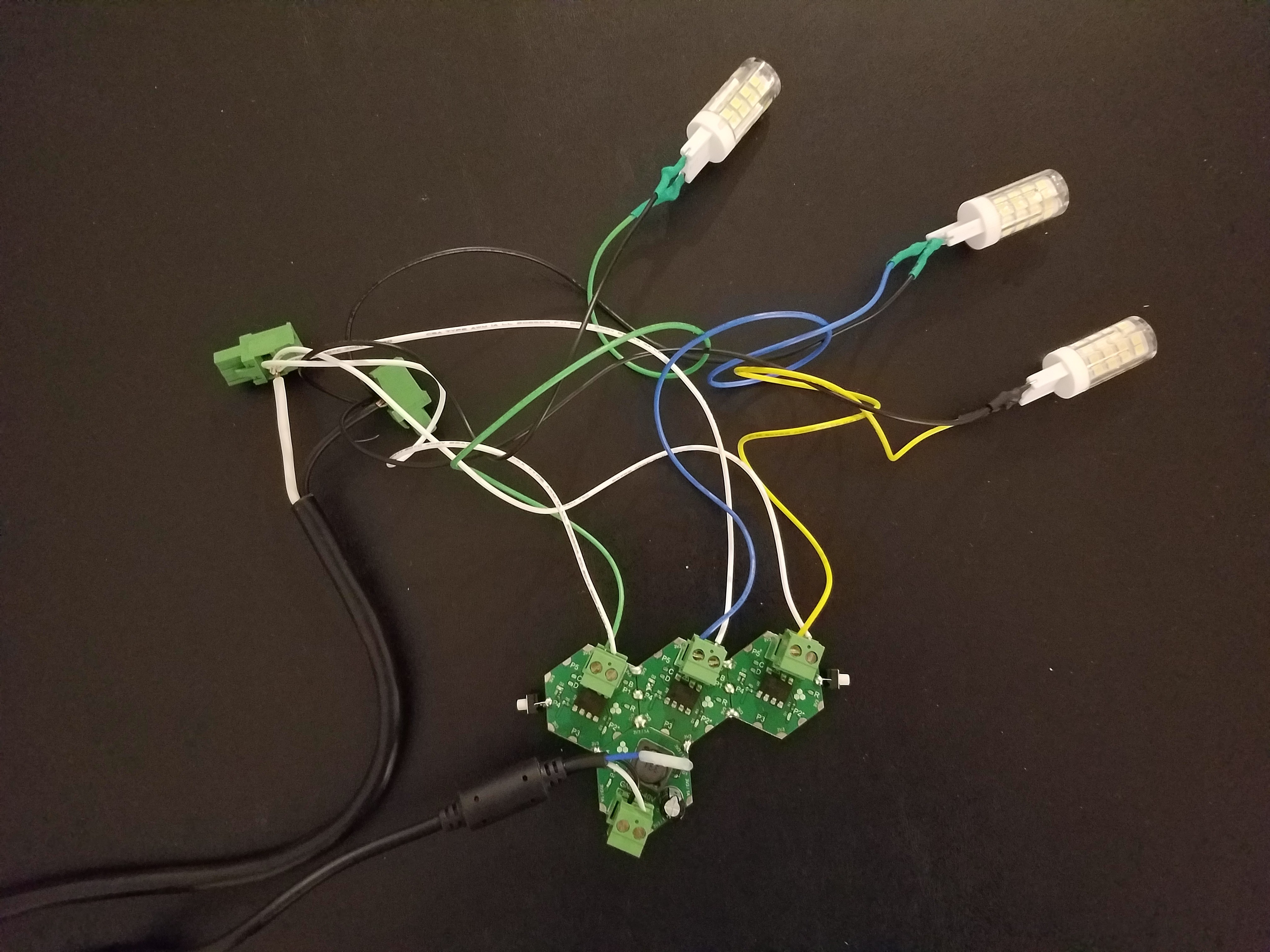
- One with the AC LED lamps
- One with one LED lamp, the AC synchronous motor and the duct fan.
How to execute this example?
The source code for this project is in the attached zip folder. Each demo example code is available in a separate C source file in User folder called main_ex1.c, main_ex2.c, etc. To run a specific example, replace the main.c file content with the content of the example file and recompile the project for all three targets. Check firmware update article for instructions on loading firmware to the modules.
Discussions
Become a Hackaday.io Member
Create an account to leave a comment. Already have an account? Log In.