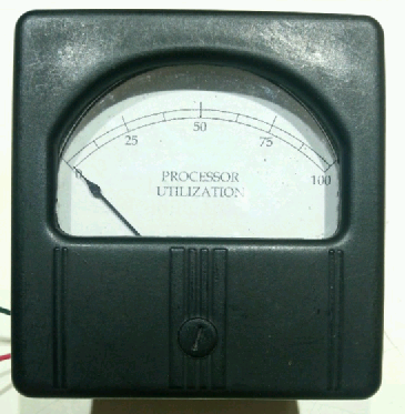
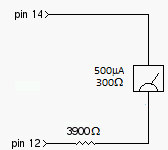
Analog meters are a current measuring device. (If you have a meter that's designed to measure voltage you can still use it in this project: it's actually a current meter with an internal resistor. Simply open the meter up and short out the internal resistor by soldering a piece of wire across it.) For this project, we'll need to measure a varying voltage. How do we do that? Simple: insert a resistor in series with the meter! It's value determines the voltage that drives the meter to full scale. We'll use the PWM output to generate a varying voltage, and the gpio program (part of WiringPi) to set the PWM value.
Here's the spiffy meter I used: it's from the 1950s. It's a 500uA meter with a resistance of 300 ohms. It was originally a Db meter, but with some modification (read: ripping out a bunch of parts) I turned it back into a plain old micro-ammeter. I made a custom scale since the original was logarithmic:

 mircemk
 Pablo Antonio Camacho Jr.
 jaromir.sukuba