Close
0%
0%

2WD Voice Controlled Robot with Arduino

Shows how to build a 2WD (two-wheel drive) voice-controlled robot using an Arduino and BitVoicer Server.

Similar projects worth following
In this project I am going to show how to build a 2WD voice-controlled robot. Although I am controlling only DC motors to move the robot, the same approach can be used to voice-control stepper motors and servo motors, so if you are planning on building any voice-controlled robot that perform mechanical movements, this project can serve as reference for your project.

To build this robot, you will basically need one 2-wheel chassis, one Arduino board, one DC motor driver shield, one BitVoicer Server license, one WiFi module and one pre-amplified microphone. Regarding the components, there is a huge variety of them in the market and you can achieve the same results using different combinations. In Step 1, I give a few details about some components used in the robot, so if you need to change some of them, just look for components with similar features.

The following procedures will be executed to transform voice commands into robot movements:

  1. Audio waves will be captured and amplified by the Sparkfun Electret Breakout board;
  2. The amplified signal will be digitalized and buffered in the Arduino using its analog-to-digital converter (ADC);
  3. The audio samples will be streamed to BitVoicer Server using the Microchip WiFi module;
  4. BitVoicer Server will process the audio stream and recognize the speech it contains;
  5. The recognized speech will be mapped to predefined commands that will be sent to the Arduino;
  6. The Arduino will identify the command and define which DC motors will be used, for how long and at what speed;
  7. The motor driver will be activated to provide the required voltage and current to move the motors.

List of Materials:

  • 1 × Arduino UNO
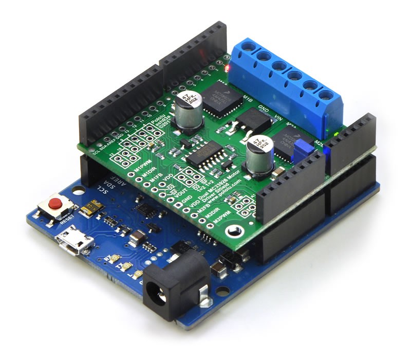
  • 1 × Pololu Dual MC33926 Motor Driver Shield
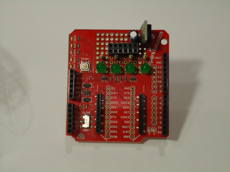
  • 1 × SparkFun XBee Shield
  • 1 × Microchip RN171VX Module w/ Antenna
  • 1 × SparkFun Electret Microphone Breakout

View all 16 components

  • 1
    Step 1

    Getting to Know the Components

    In this step I give some important information about the robot’s components and how to prepare them for mounting.

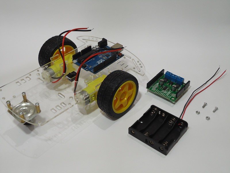
    In the first place, the heart of the robot: an Arduino UNO R3. Although I am using an Arduino UNO, you can use other Arduino boards to mount your robot. I decided to use an Arduino UNO because it is, by far, the most popular Arduino board and more people would be able to rebuild this robot. If you have an Arduino DUE, you can also add voice responses to your robot as I did in this project.

    To move the DC motors, I used this Pololu shield. It is a dual motor driver capable on controlling 5 to 28V DC motors and deliver up to 3A continuous current per motor. Although I think this is a very good shield, what impressed me the most in Pololu’s products is their clear and detailed documentation. Besides, Pololu provides an Arduino library that makes really simple to control the motors. You just have to pass the speed and direction (negative or positive values) to the setSpeeds function. If you opt to use another DC motor driver, pay attention to the pins used by the driver because they cannot conflict with any other pin used by the robot. The Pololu shield uses the following Arduino pins: digital 4, 7, 8, 9, 10 and 12; analogic 0 and 1; ground; and 5V. The most important aspect here is that only pins 9 and 10 are used as PWM pins and the timer used to generate pulses on these pins is not the same timer (timer 2 on the UNO) used by the BVSMic class from BitSophia.

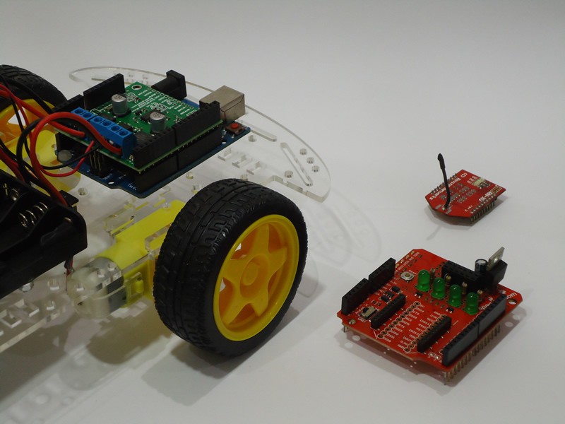
    To establish communication with the server and access BitVoicer Server services, I use the Microchip WiFi RN171VX module. Two main features stand out in this module: all communication can be done through the serial port in a simple manner; and the module has the same form factor as most of the popular XBee modules. In other words, if you already have an XBee shield, you most likely will not need to buy the Sparkfun shield I use in this robot.

    Using the XBee shield with the Microchip WiFi module made mounting the robot pretty easy. However, I have identified a problem in this combination. It is known that working with radio is extremely complex and considered by some people as “voodoo magic”. Well, I noticed that while the WiFi adapter is on and transmitting data, a strong interference occurs in the audio signal measured by the Arduino ADC. I was not able to precisely identify the source of this interference, but I have two possible sources: the module peak current draws (up to 240mA) are not being properly decoupled and compromise the reference voltage provided to the Arduino ADC; or the signal emitted by the antenna is being picked up by some exposed pins right below the module. Usually, WiFi module manufacturers instruct designers to avoid placing anything (even ground planes) near the antenna precisely to prevent this kind of issue.

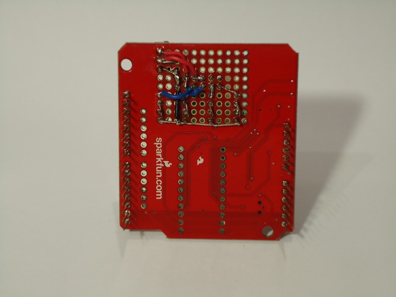
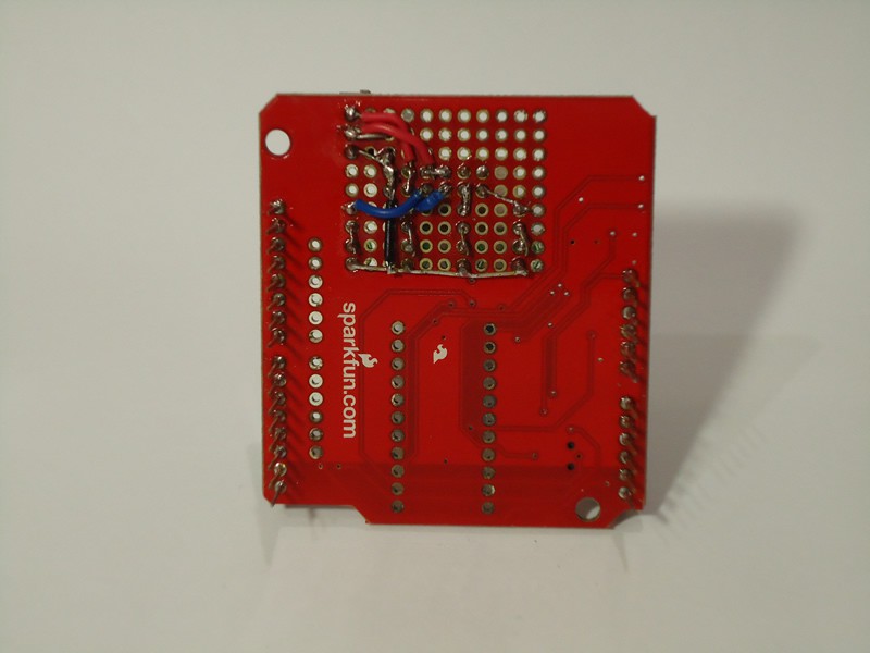
    To correct the problem described above, I soldered a 3.3V voltage regulator and one 10μF electrolytic capacitor to the Sparkfun shield so they could provide the reference voltage to the Arduino ADC. The same power source is used by the Sparkfun electret microphone. It solved the peak volume problems I was seeing in the BitVoicer Server Manager. Even during silence periods, the audio level was getting as high as 35 (0-100) in the Server Monitor. If you see the same thing happening in your project, investigate what is going on with the audio signal measured by the Arduino ADC.

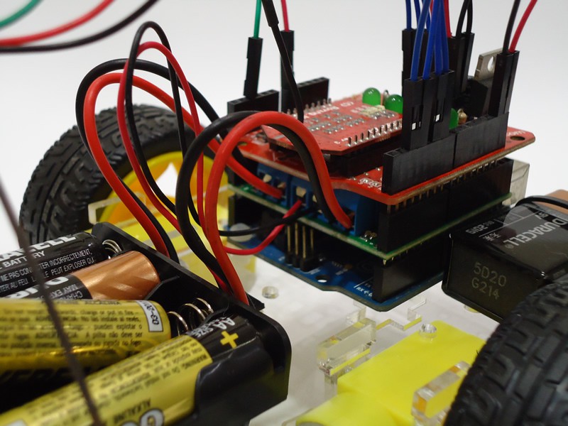
    I decided I was also going to use the prototyping space available in the Sparkfun shield to solder a few LEDs that tell the status of some BitVoicer Server functionalities. In the picture below, from the left to the right, the following information is exposed by the LEDs:

    • Indicates whether BitVoicer Server is running and/or if the connection remains active;
    • Indicates whether the data forwarding service is running;
    • Indicates whether a speech recognition engine has been assigned to the Arduino;
    • Indicates whether we are in the activation-word-activated-period. This LED lights up only when the activation word is identified.

    Regarding the preamplified electret microphone, there are many options available in the market: Sparkfun, Adafruit, RoboCore, Hackerstore and probably many others. To use the code I am posting on this project, make sure the microphone you are buying is analogic, the required voltage is available in your Arduino board, and the amplification is high enough (usually 100x for electret microphones) for the Arduino ADC.

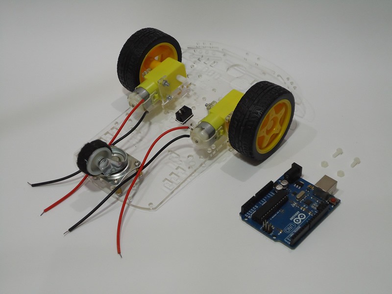
    The 2WD chassis used in the robot is one of the cheapest and most popular on ebay. The complete kit contains one acrylic platform, two plastic/rubber wheels, one 360º wheel, two DC motors with gear (1:48 ratio), one 4xAA battery holder, two speed encoder disks and a set of screws.

  • 2
    Step 2

    Mounting

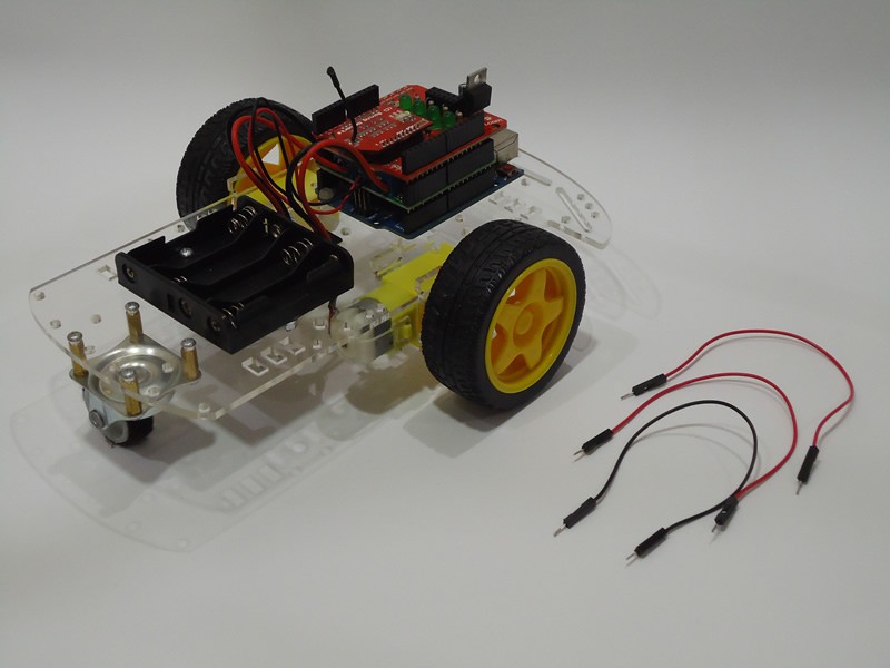
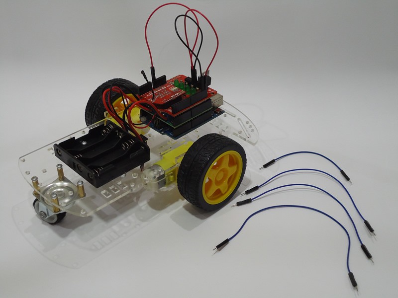
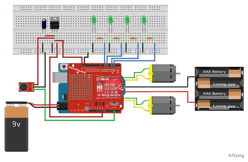
    Let’s get to work! In this step you have to mount all components on the chassis as shown in the pictures below.

    If you do not want to solder the LEDs and the voltage regulator on the XBee shield, you can mount them on a small breadboard as shown in the picture below. In this case, choose a reduced size breadboard so you can fix it somewhere on the chassis without further problems.

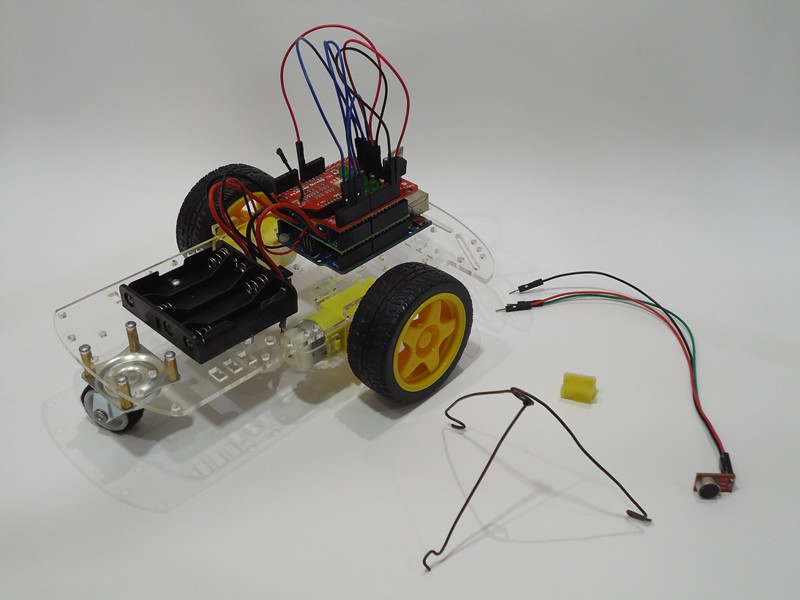
    In the pictures above, you can note that I made an iron wire support to hold the microphone. You can also see that I glued a strip of felted fabric around the 360º wheel. I took these two measures to try to reduce the noise generated by the robot and captured by the microphone when the robot is moving. I even cut a small piece of sponge to isolate the microphone wires from the support. Of course it was not 100% effective, but it reduced the noise a little bit and improved the accuracy of the speech recognition.

  • 3
    Step 3

    Setting Up the WiFi Module

    As I said in Step 1, the Microchip RN171VX WiFi module can be totally operated through the serial port. This makes extremely easy to set up the module because all commands are simple strings sent through the Arduino serial port. You just have to send a string containing “$$$” to enter command mode, send the commands and then send a string containing “exit” to return to data mode.

    The code below is the code I used to set up the WiFi module in my home network. You will have to change the parts of the code marked as “XXXXXX” with information from your WiFi network. Three commands will have to be changed:

    • set wlan ssid XXXXXX: replace the XXXXXX with your network name (SSID);
    • set wlan phrase XXXXXX: replace the XXXXXX with your network password;
    • set ip address XXXXXX: replace the XXXXXX with the IP address (static) you wish to set to your WiFi module.
    void setup() 
    { 
      Serial.begin(115200); 
      pinMode(13, OUTPUT); 
      delay(5000); 
      Serial.print("$$$"); 
      delay(1000); 
      Serial.println("set wlan auth 4"); 
      delay(1000); 
      Serial.println("set wlan phrase XXXXXX"); 
      delay(1000); 
      Serial.println("set wlan ssid XXXXXX"); 
      delay(1000); 
      Serial.println("set wlan channel 0"); 
      delay(1000); 
      Serial.println("set wlan join 1"); 
      delay(1000); 
      Serial.println("set wlan tx 0"); 
      delay(1000); 
      Serial.println("set ip dhcp 0");
      delay(1000); 
      Serial.println("set ip address XXXXXX"); 
      delay(1000); 
      Serial.println("set comm remote 0"); 
      delay(1000); 
      Serial.println("set comm close 0"); 
      delay(1000); 
      Serial.println("set comm open 0"); 
      delay(1000); 
      Serial.println("set comm size 500"); 
      delay(1000); 
      Serial.println("set comm time 50"); 
      delay(1000); 
      Serial.println("set uart baud 115200"); 
      delay(1000); 
      Serial.println("set uart flow 0"); 
      delay(1000); 
      Serial.println("save"); 
      delay(1000); 
      Serial.println("exit"); 
      delay(1000); 
      digitalWrite(13, LOW);
    }
    
    void loop() { }

    In my WiFi network, the authentication method is WPA2-PSK. If your network uses a different authentication method, you will also have to change the set wlan auth command. Check out the WiFi module documentation (section 4.3 Set Commands) to find out which value is the correct one for your network.

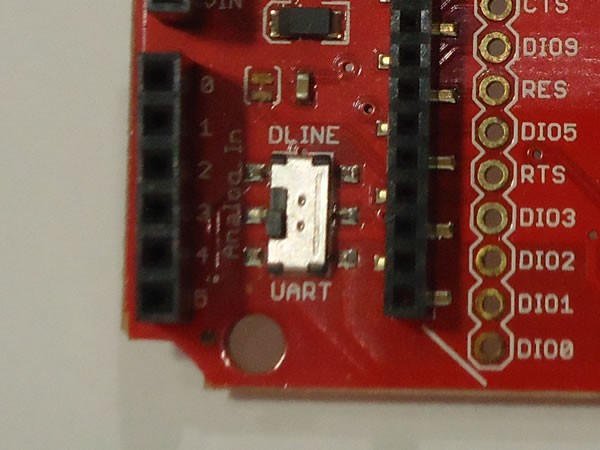
    There is an important detail about the Sparkfun shield and its small switch (picture below). To upload code to the Arduino using its USB interface, the switch must be set to the DLINE position. For the Arduino to send/receive data through the WiFi module using its serial port, the switch must be set to the UART position. This is necessary because the WiFi module and the USB chip on the Arduino UNO use the same serial port in the ATmega microcontroller. If the switch is set to UART and you try to upload code to the Arduino, an error message will be displayed in the Arduino IDE.

    To upload the code above to the Arduino and allow the Arduino to set up the WiFi module, follow the steps below:

    1. Set the switch to the DLINE position;
    2. Open the Arduino IDE, paste the code above into it and upload the code;
    3. As soon as the upload finishes, you will have 5 seconds (delay at the beginning of the code) to change the switch to the UART position before commands are sent to the WiFi module. If the first command is lost, none of the others will work. In this case, simply reset the Arduino so the sketch can run again from the beginning.

    During the module configuration, which takes about 25 seconds, the module LEDs will blink differently from its standard pattern. At this moment you will know the WiFi module is being configured.

    After the module is configured, try to ping (Command Prompt --> “ping [IP Address]” --> press Enter) the module using the IP address specified in the set ip address command. If you do not get a response from the module, something went wrong in the previous steps.

View all 7 instructions

Enjoy this project?

Share

Discussions

Similar Projects

Does this project spark your interest?

Become a member to follow this project and never miss any updates