 David Brown
The core of the printer will be an array of 8 laser controller chips (iC-HKB) to give threshold current and then 7 further bits of resolution. As the chips use a single voltage to control power output, having individual units allows better calibration for each level.
The levels can be set to map the greyscale values directly, to account for the effects of absorption and depletion that gives rise to the characteristic curve of exposure versus tone; to get a darker exposure you need longer than expected as a proportion of photons will be absorbed and not contribute, (logarithmic/power type curve versus straight line).
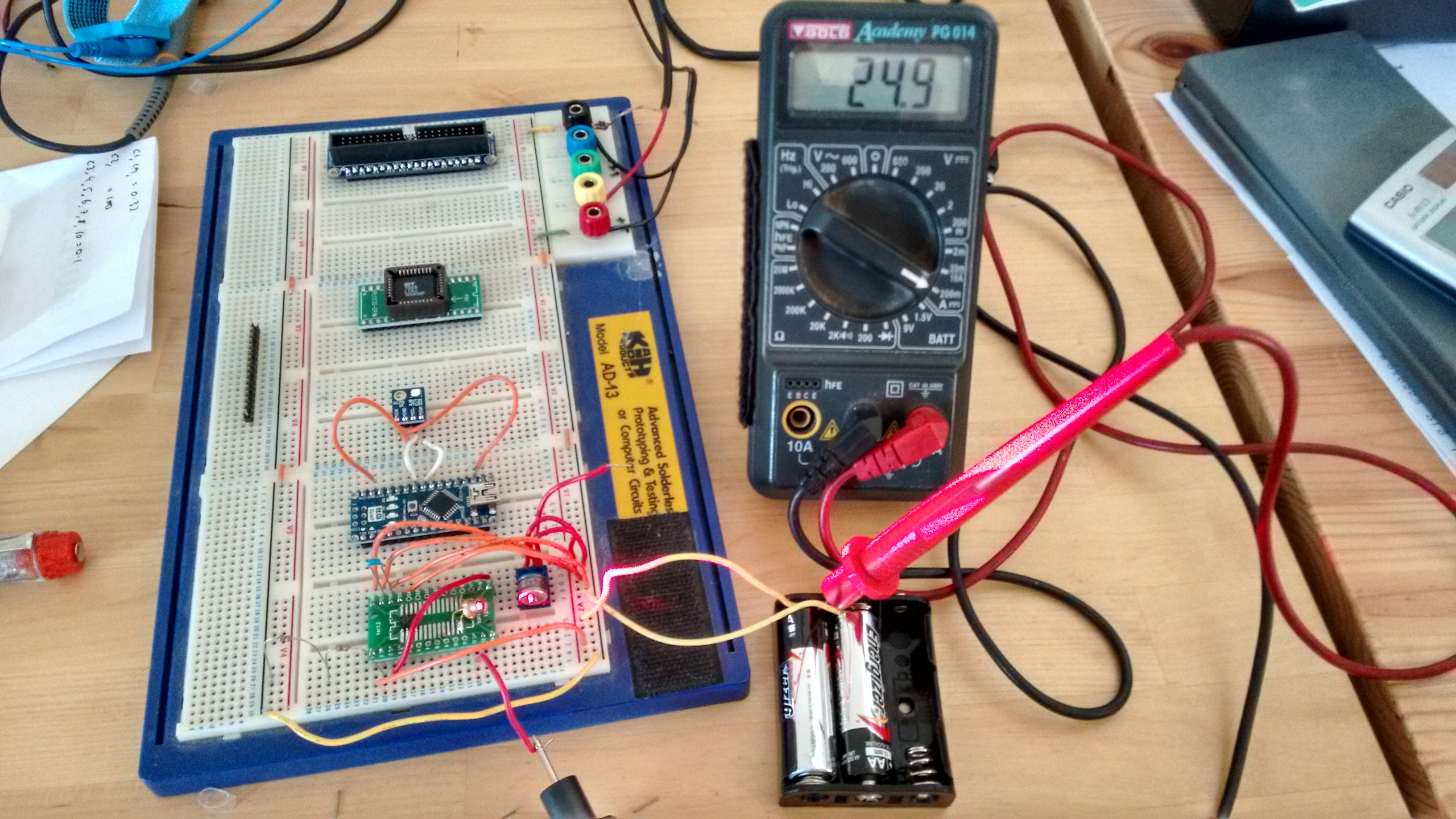
I decided to test one of the iC-HK units, to see how it behaves, connecting up to one of the small red laser diodes that will be used for the position sensing (data dump trigger) of the rotating mirror.
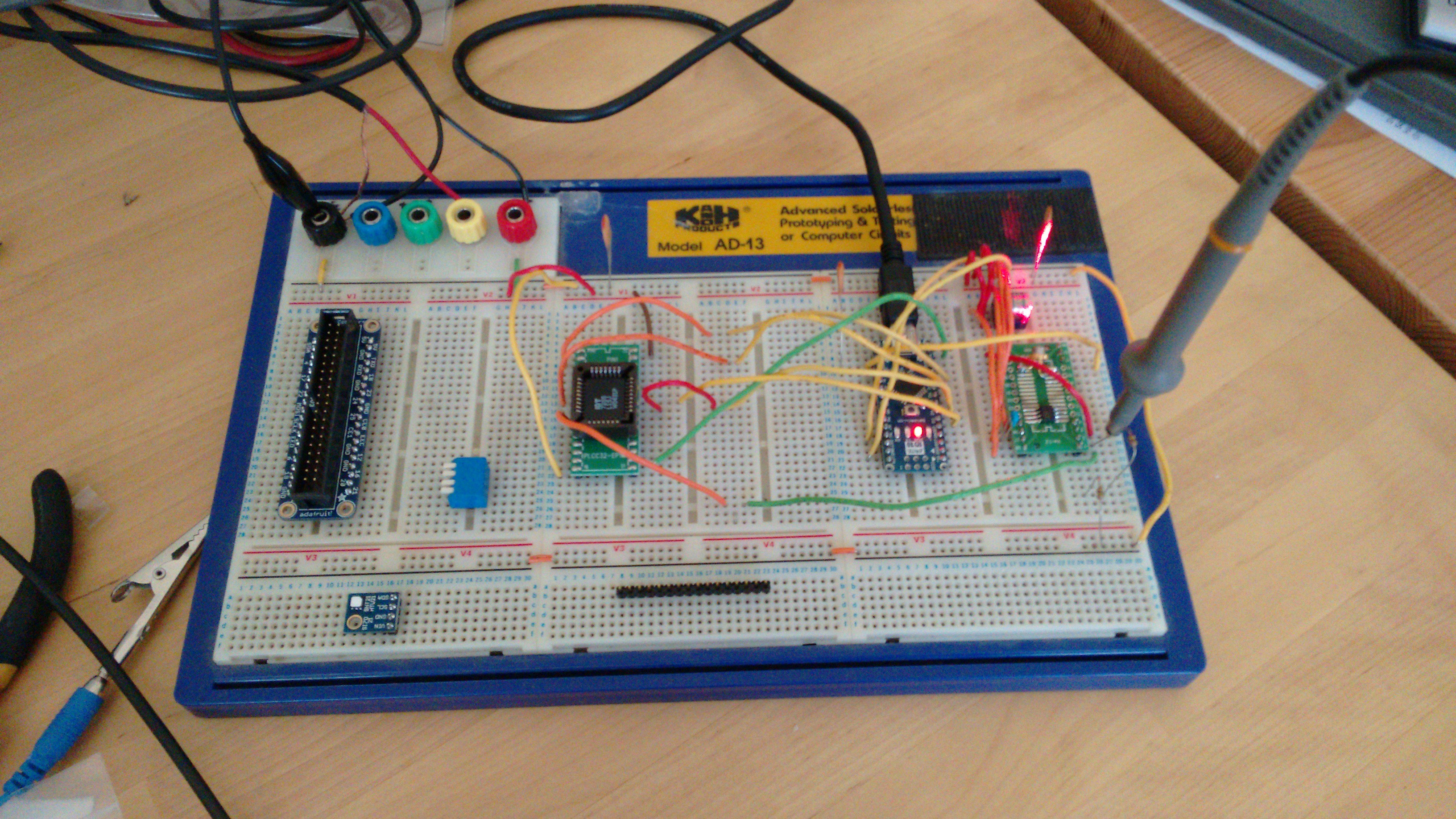
I followed this up by connecting the FIFO to the arduino and switching the laser using the data stored in the FIFO.
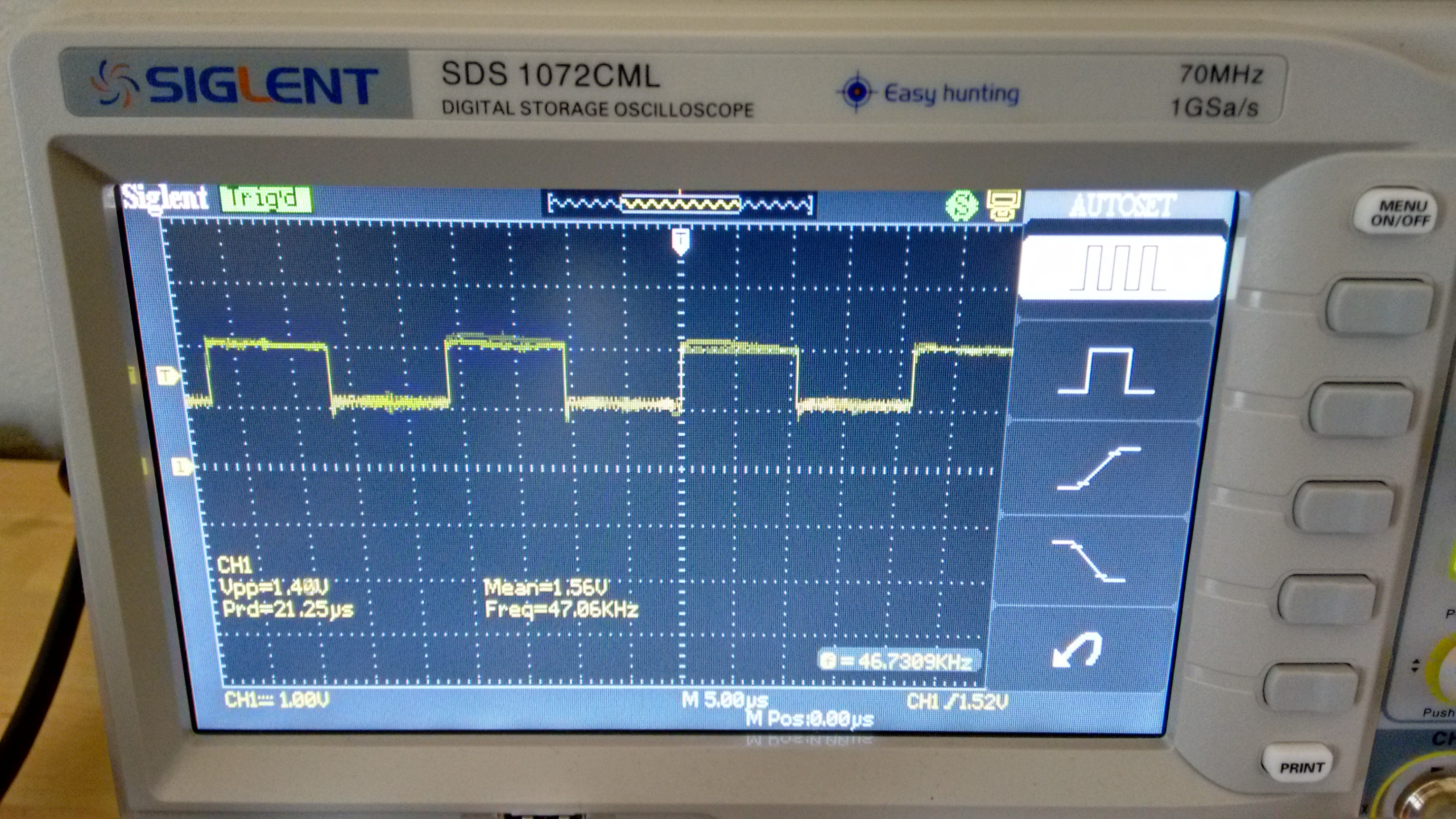
I need to delve into the arduino registers to get higher frequencies, but so far it is behaving as expected. The FIFO is rated for a max speed of 40MHz, the design calcs indicate a speed of 10MHz required, so I'm not expecting any issues.
Discussions
Become a Hackaday.io Member
Create an account to leave a comment. Already have an account? Log In.