I've built up the core functions on the arduino that control the following I2C sub-systems;
- Temp & humidity sensor - ok
- trigger laser DAC - ok
- x8 UV laser DAC - ok
- laser current monitor ADC - ok
- TEC temperature set point DAC - ok
- I/O extender & frequency generator - ok
- arduino direct pins I/O - partial
Next up is to design the parsing system to allow the functions to be called by the raspberry pi over serial link.
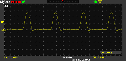
The clocking out of the frequency generator has been modified to give a better behaviour for the FIFO read out. Originally I was using the non-inverted output from the AD9850, assuming that the waveform would be symmetric.
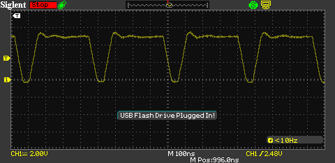
However, it seems that because I am using a 3.3v drive clock (DSC1001 - MEMS 125MHz oscillator) that there is bias, because this is less than the expected 5v, which in this case is a good thing, as it means that there is a greater 'on' time from the inverted output. Resulting in the FIFO being held at 'read' longer than it is 'off' whilst clocking to the next bit.

 Inverted output
 David Brown
Discussions
Become a Hackaday.io Member
Create an account to leave a comment. Already have an account? Log In.