Well one milestone has been completed and that is getting the laser controller board tested. This covers the following;
- Setup control of the DAC to allow calibration of the control voltage to the iC-HKB laser control ICs. The coarse level current control is via a resistor, with fine control via the voltage (tuning).
- Setup of the FIFO through the Flexible Flat Cable (FFC) to allow loading of data from the arduino used in testing
- Setup of the ADC that, in conjunction with a current sensing resistor allows the control voltages to be calibrated against a laser diode test load (diodes and a thick film resistor)
- Overview of components tested;
- 9bit FIFO
- I2C x8 12bit DAC
- I2C 16bit ADC
- x8 iC-HKB laser diode controllers
A number of functions were needed to step through the process and allow confirmation of the data reported by the ADC. And then to speed up the read out clocking to test the behaviour at speed. I would like to test with the diode, but have yet to get the heat sink design finalised and fabricated. And without heat sinking it will burn out.


I ran each of the ICs individually to allow me to measure the voltage over the current sense resistor with the multimeter (resolution was ~0.2mA) which shows reasonable match in readings. Likely within the error range for both devices.

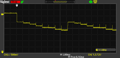
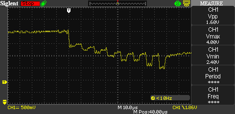
Plot below is speeding up the read out to the max achievable by the arduino through bit banging the read pin of the FIFO. My calculations indicate that a clock out speed of ~1.5MHz is required, this is the main reason that i'm using a hardware readout system to generate the the clock pulse train and to enable and disable it; the secondary red laser diode and a pair of photo diodes. The raspberry Pi will have 9ms to re-load the FIFO for the next line of data.

 David Brown
Discussions
Become a Hackaday.io Member
Create an account to leave a comment. Already have an account? Log In.