 Mike Rigsby
I'm adding construction details here . . . after the video.
Mato II Construction
Parts:
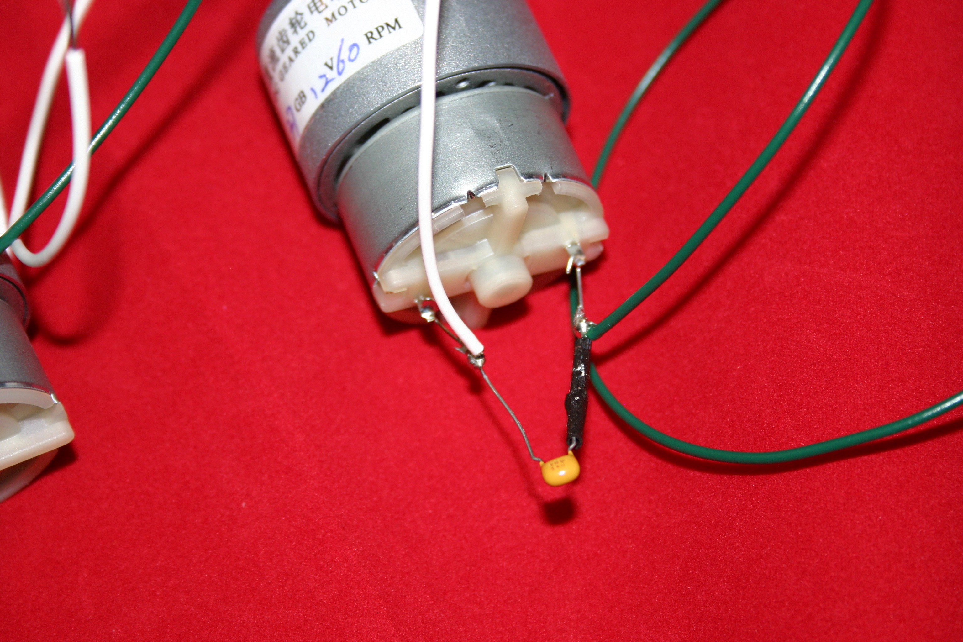
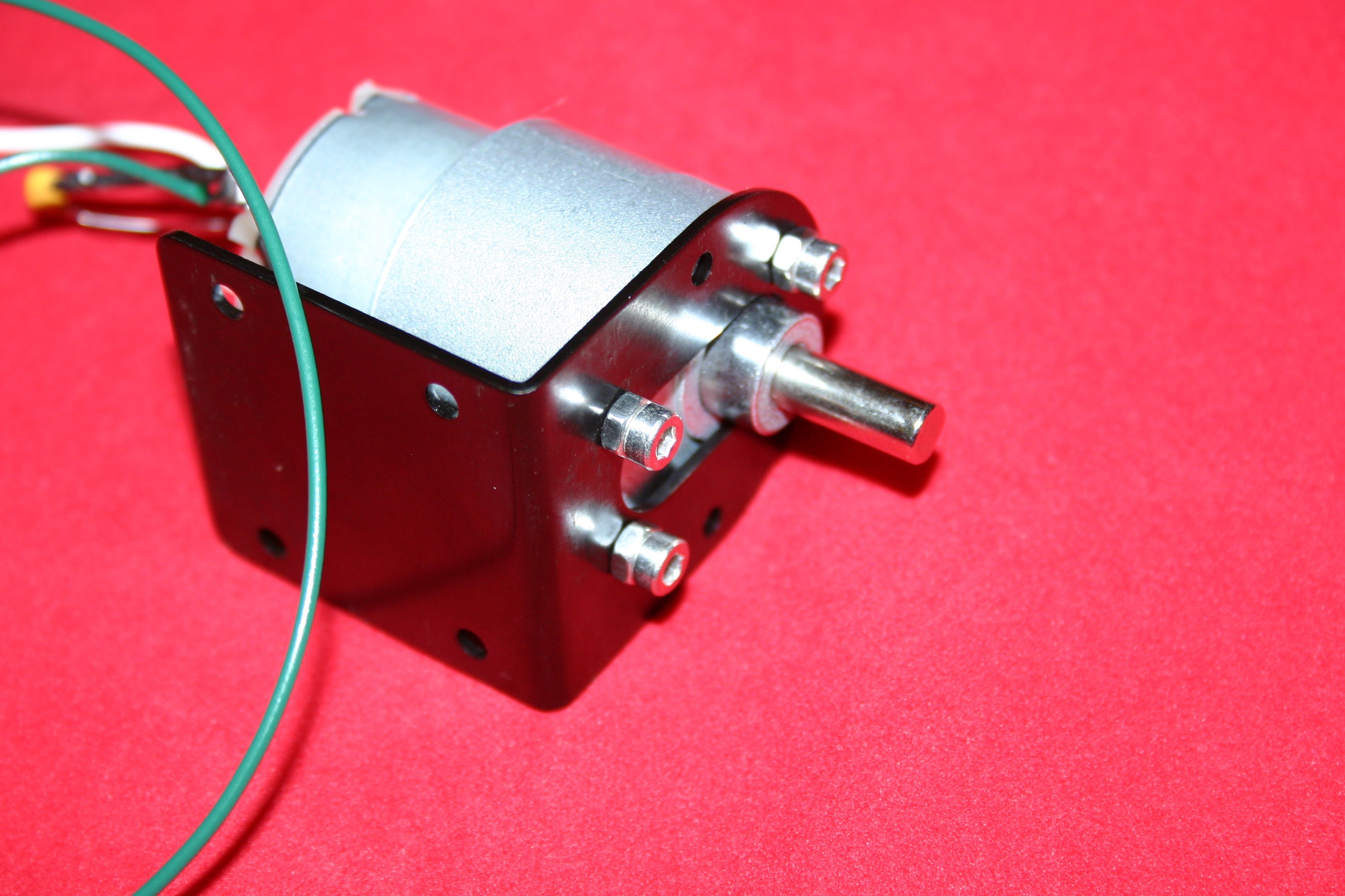
(2) 12 V dc 60 rpm gear motorshttp://www.amazon.com/Nextrox-Mini-Torque-Electric-Motor/dp/B00BX54O8A?ie=UTF8&psc=1&redirect=true&ref_=oh_aui_detailpage_o06_s01
(2) Motor bracketshttp://www.amazon.com/uxcell-Geared-Mounting-Bracket-Coupling/dp/B00TK0X03U?ie=UTF8&psc=1&redirect=true&ref_=oh_aui_detailpage_o06_s00
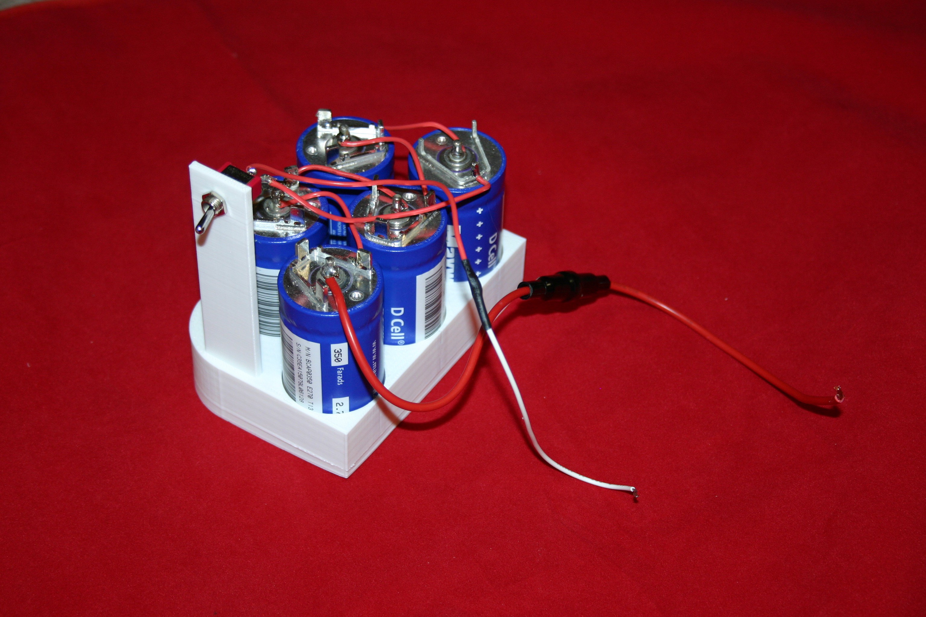
(5) 350 farad 2.7 volt capacitorshttp://www.amazon.com/Maxwell-Technologies-Supercapacitors-Ultracapacitors-2-7Volts/dp/B0137ILPOQ/ref=sr_1_2?s=industrial&ie=UTF8&qid=1463673653&sr=1-2&keywords=350+f+capacitor
These are available for less cost per unit (minimum order ten) at: https://www.tecategroup.com/store/index.php?main_page=product_info&products_id=1221
(1) DC step up/step down converter modulehttp://www.amazon.com/Converter-3-5-28V-1-25-26V-Adjustable-LM2596S/dp/B008ATU2X8?ie=UTF8&psc=1&redirect=true&ref_=oh_aui_detailpage_o06_s00
(2) Eureka round vacuum beltshttp://www.amazon.com/Eureka-Style-RD-Vacuum-Belts/dp/B00002N62X?ie=UTF8&psc=1&redirect=true&ref_=oh_aui_detailpage_o03_s00
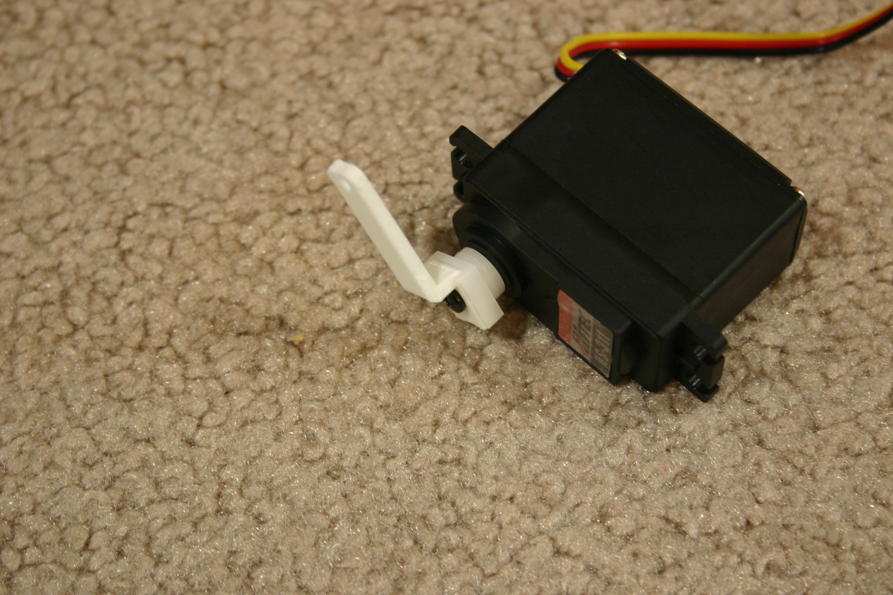
(2) Hitec HS 311 servo motorshttp://www.amazon.com/Hitec-31311S-HS-311-Standard-Universal/dp/B0006O3WVE?ie=UTF8&psc=1&redirect=true&ref_=oh_aui_detailpage_o09_s00
(1) DC digital meterhttp://www.amazon.com/DROK-Digital-Voltmeter-Voltage-Display/dp/B00C2NTJHS?ie=UTF8&psc=1&redirect=true&ref_=oh_aui_detailpage_o09_s00
(1) Arduino Uno
(1) Arduino Motor shield
(12) LED’s, white
(2) .47 microfarad capacitors, Jameco.com #25558
(1) PIR sensor
Misc.:
5 amp fuse
m3X 4 with nut
#8x ¾ nuts & bolts
#6 x ½ nuts & bolts
m3 x 12 with nut
(5) 100 ohm resistor
2n2222a transistor
1n4004 diode
2-56 x ¾ screw and nut
breadboard
breadboard jumper wires
solder
heat shrink tubing
duct tape
spst switch
3d Printed Parts
Eyeball, Lower Eyelid, and base are found here and should be printed at 95% size: http://www.thingiverse.com/thing:319978/#files
These are by “sideburn” with a creative commons, attribution, non commercial license
These files are available on hackaday.io—print the .stl files; the .123dx are available for modification purposes.
arduino holder design.123dx
arduino holder.stl
body exwide.stl
breadboard mount design.123dx
breadboard mount.stl
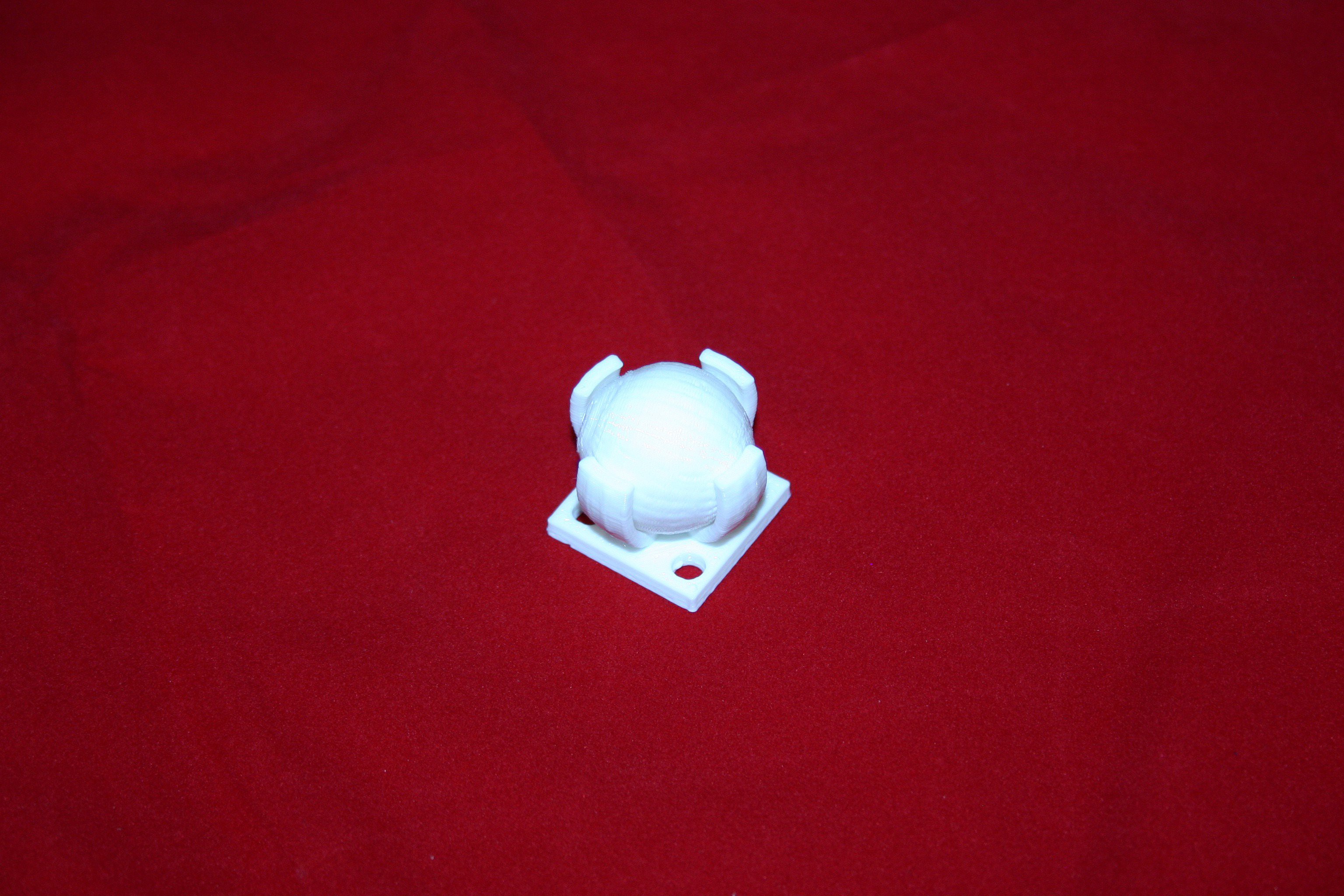
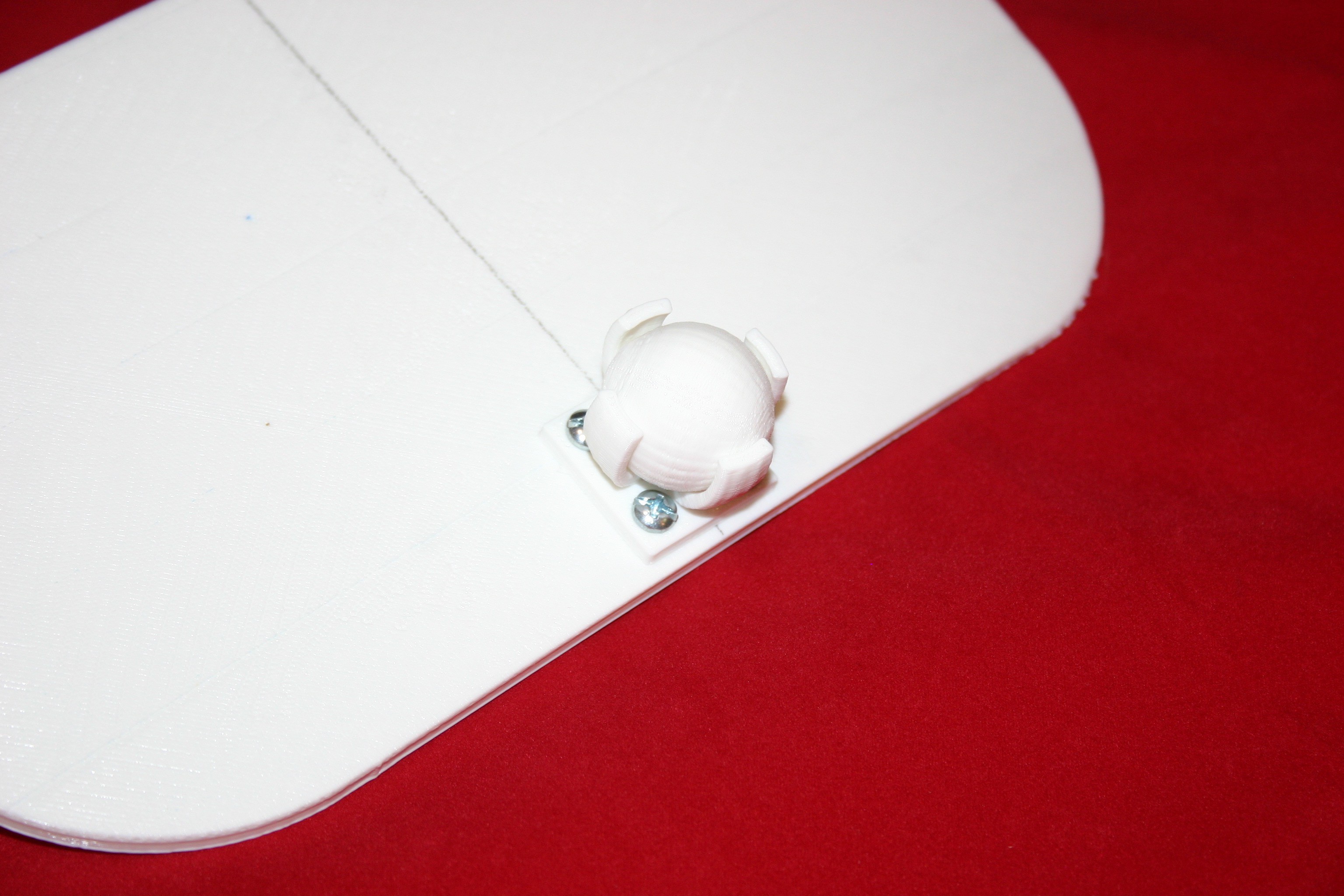
caster ball.stl
caster base.stl
eye servob design.123dx
eye servob.stl
eyeball roda.stl
eyelid connb design.123dx
eyelid connb.stl
eyelid extended.stl
mouth backing design.123dx
mouth backing.stl
mouthgard design.123dx
mouthguard.stl
mouthpiece design.123dx
mouthpiece.stl (print at 109% size)
nose eye bkta design.123dx
nose eye bkta.stl
nose pirb design.123dx
nose pirb.stl
servo hornc special design.123dx
servo hornc special.stl
ultracap holder design.123dx
ultracap holder.stl
wheel design.123dx
wheel.stl
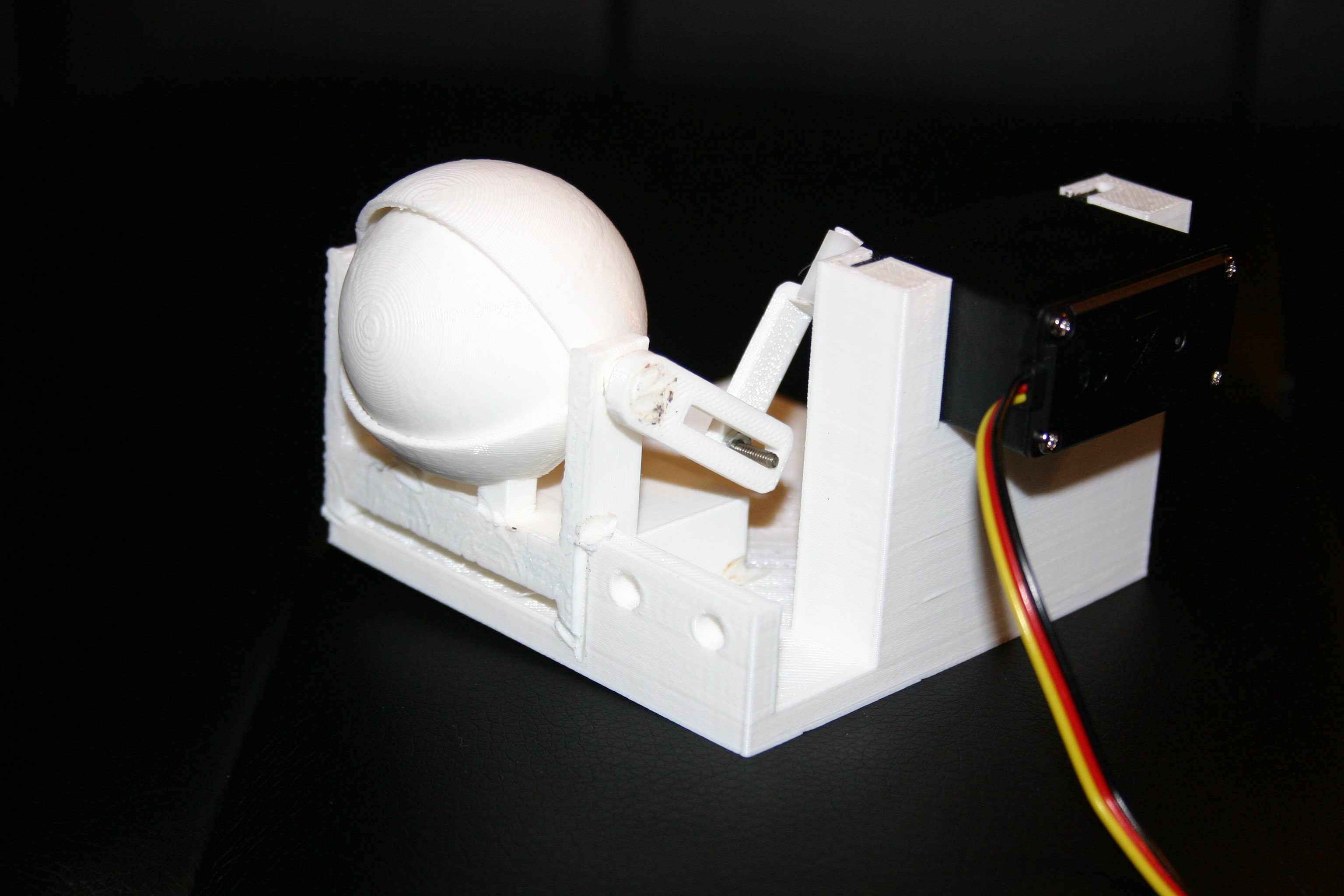
Now, let’s get started! Take the eyeball base and insert the lower eyelid, then upper eyelid, then eyeball and eyeball rod. Secure the lower eyelid, rod and eyeball base together by melting (with a soldering iron) or using glue.

Attach the connector to the eyball assembly.

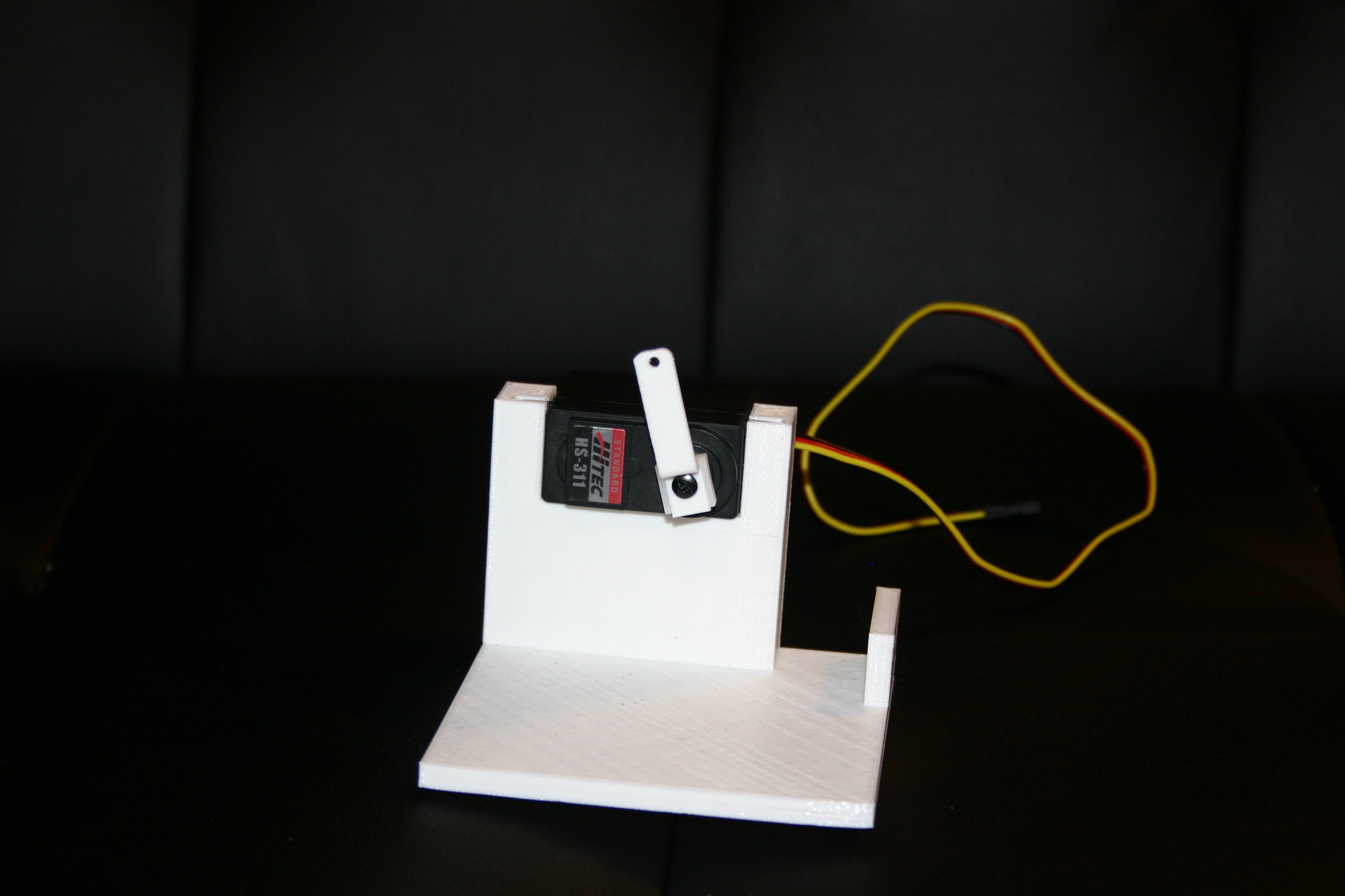
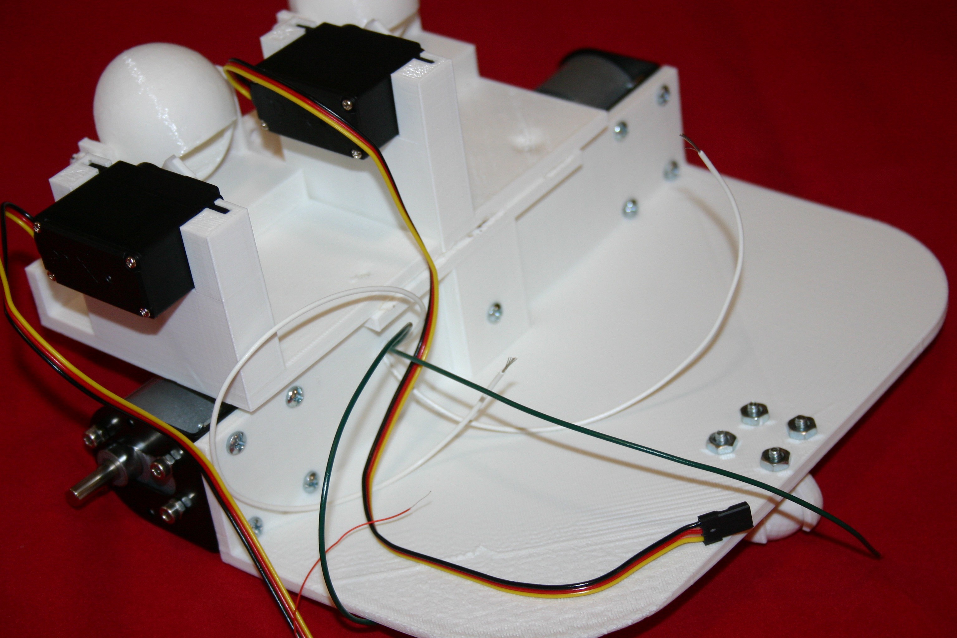
Attach the printed servo horn to the servo motor.
Place the motor/servo horn into the base.
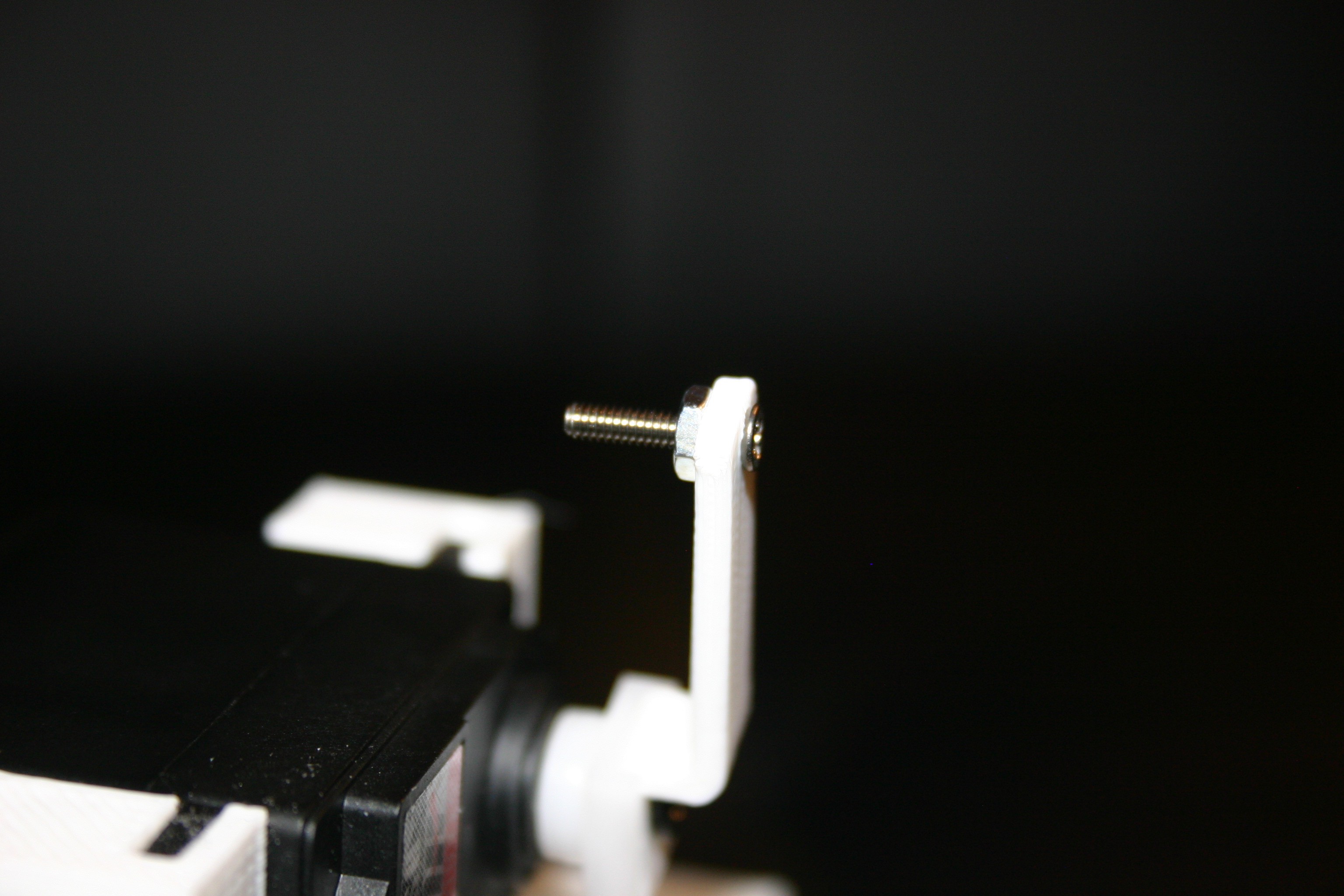
Attach a 2-56 by ½ inch screw to the printed servo horn.
Connect the servo horn to the eyelid connector. Be certain that the servo can travel enough to open and close the eyelid.
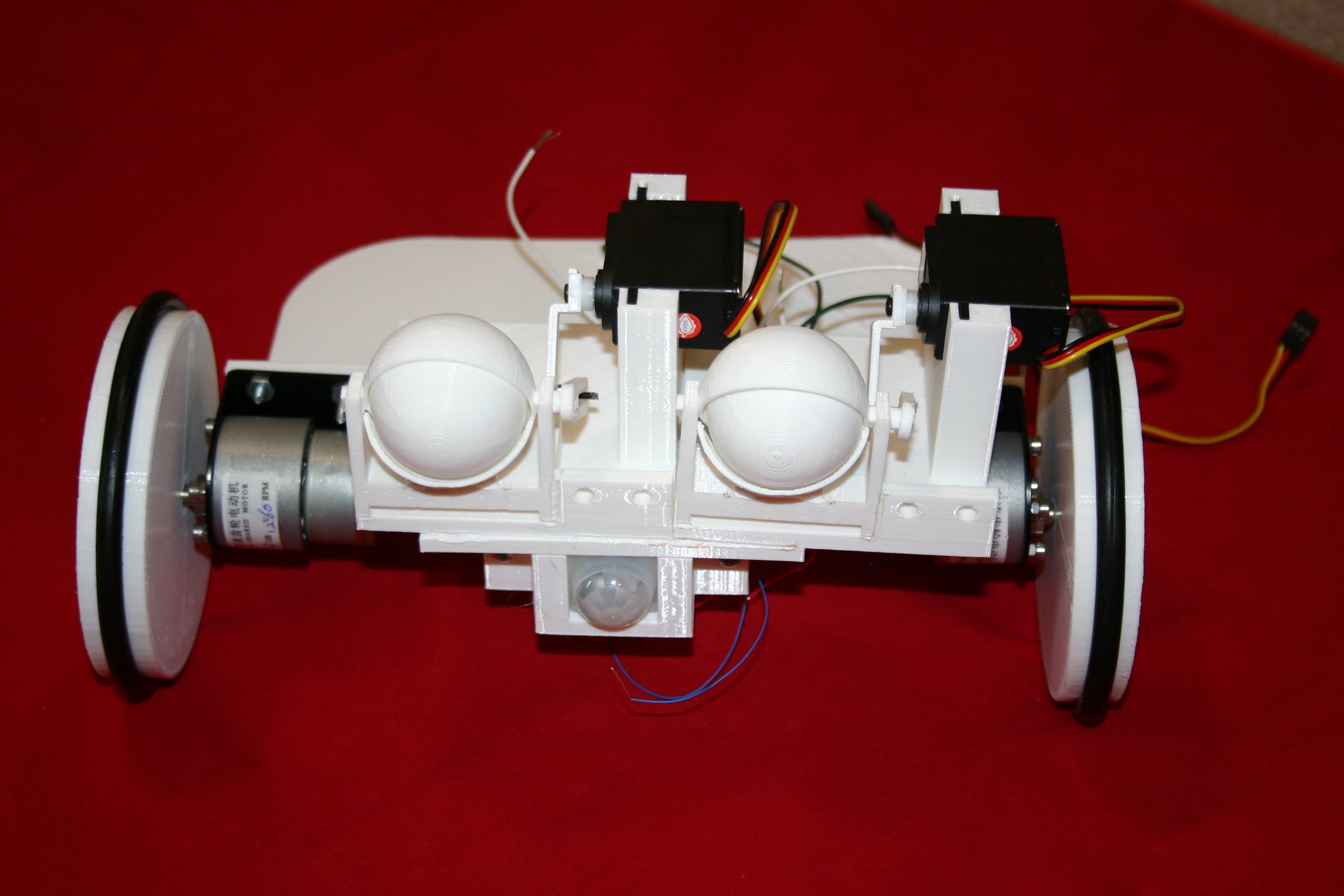
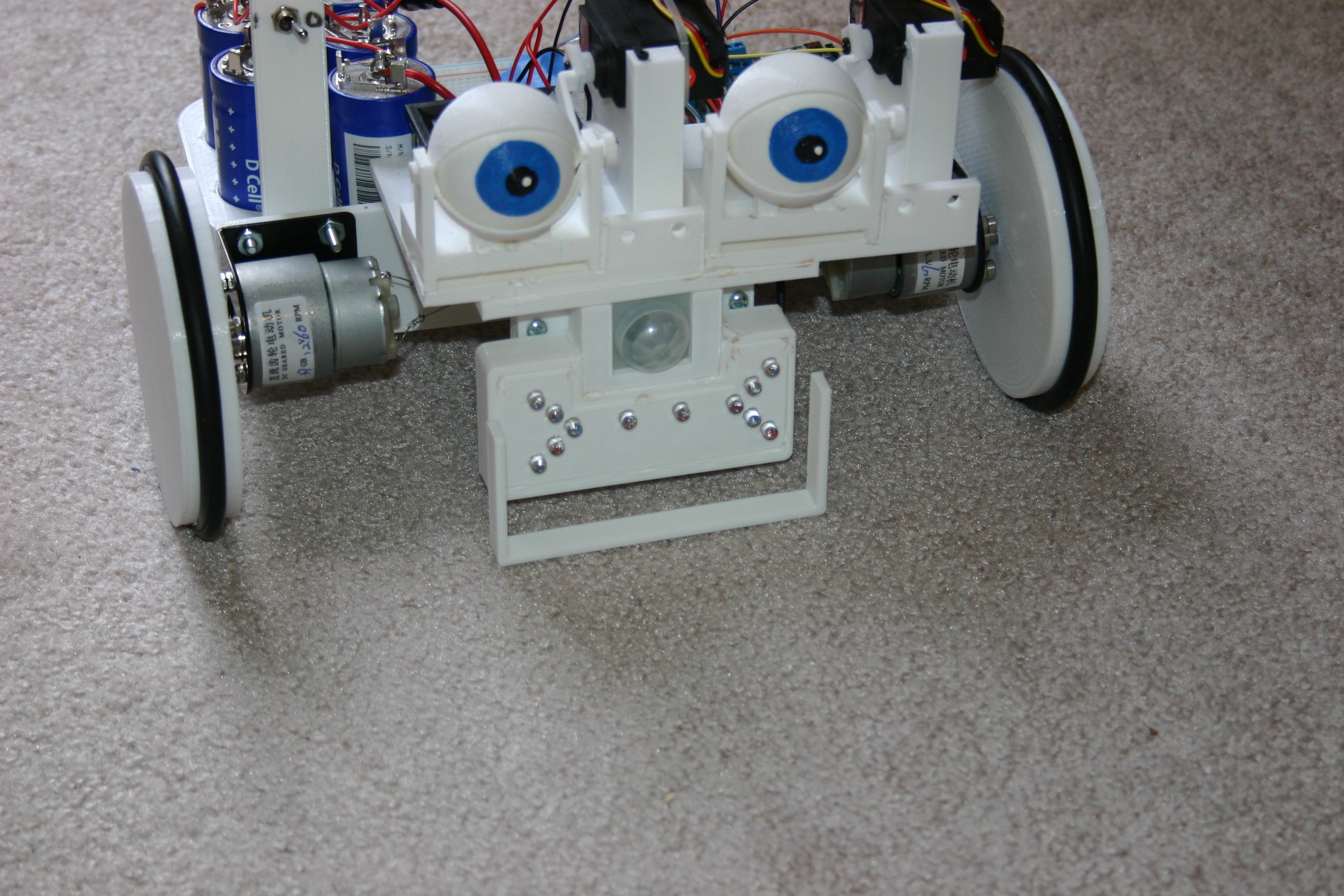
Attach the eyeballs to the nose eye bracket.
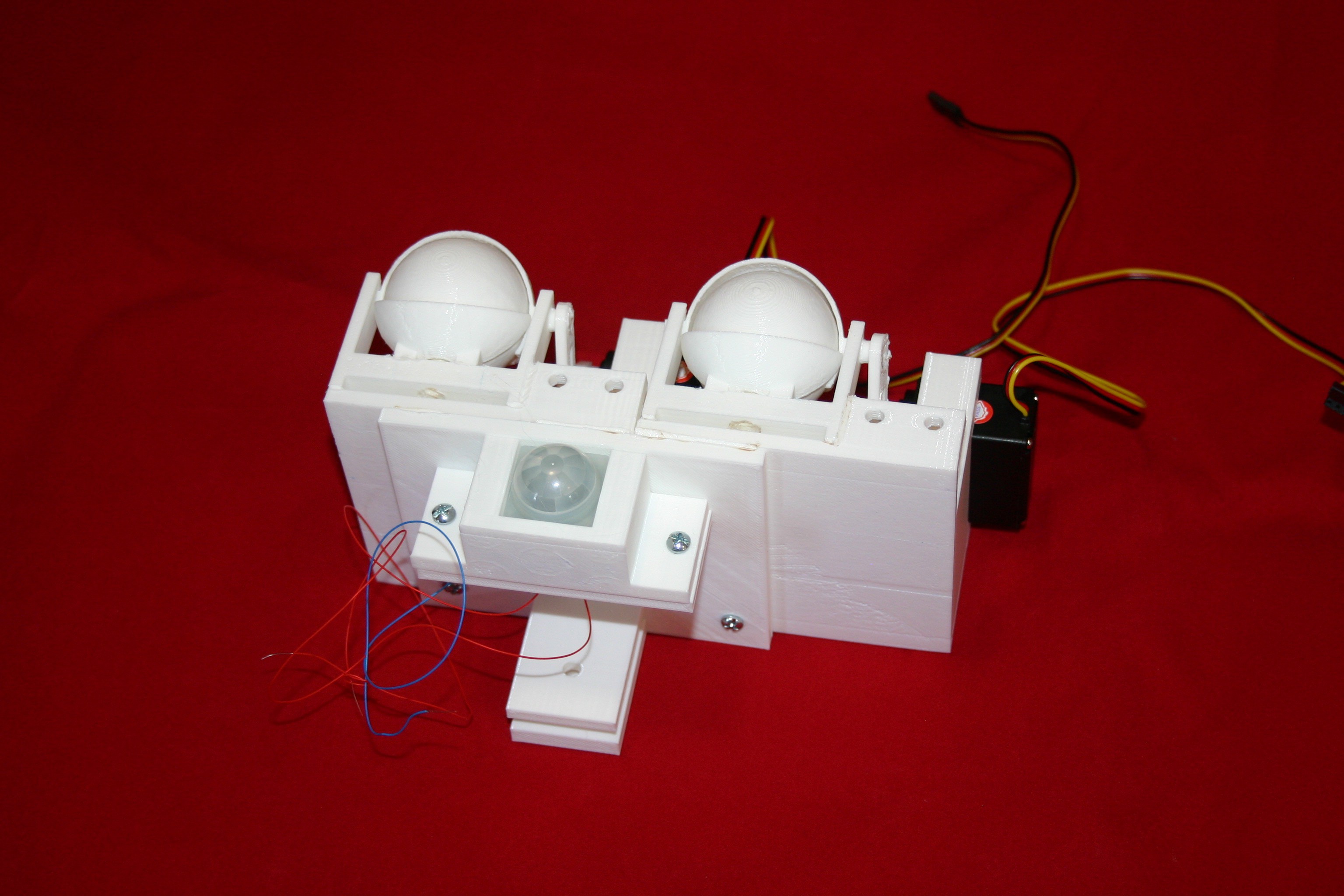
Wire and insert the PIR sensor into the eye bracket.
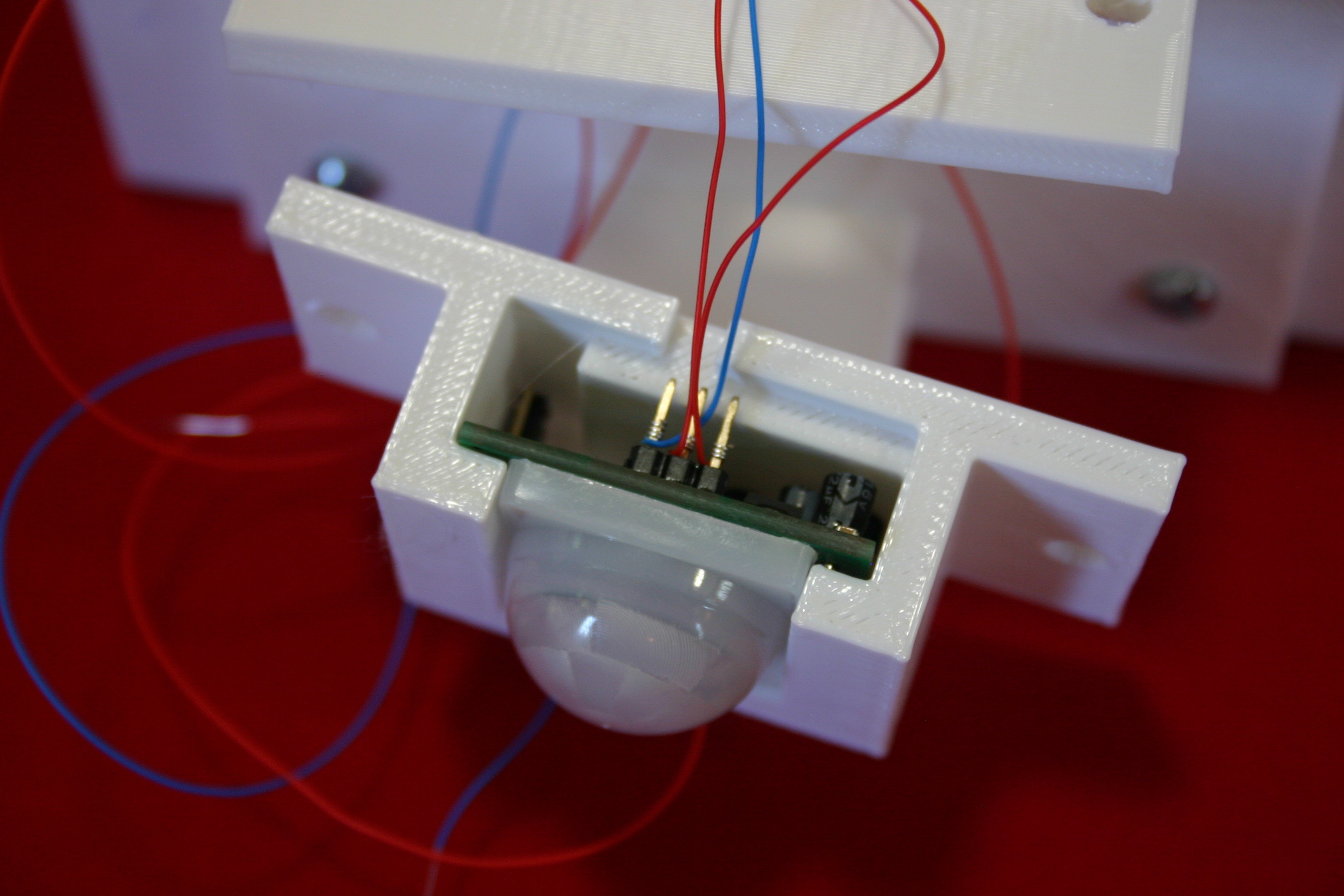
Secure the nose (PIR sensor) to the eye/nose bracket.

Push the caster ball into the caster bracket.
Add wires and a .47 microfarad capacitor to the motors.
Attach the motors to the motor brackets using m3 x 4 screws (I had m3 x 6 available, so I had to add a nut to make it fit).
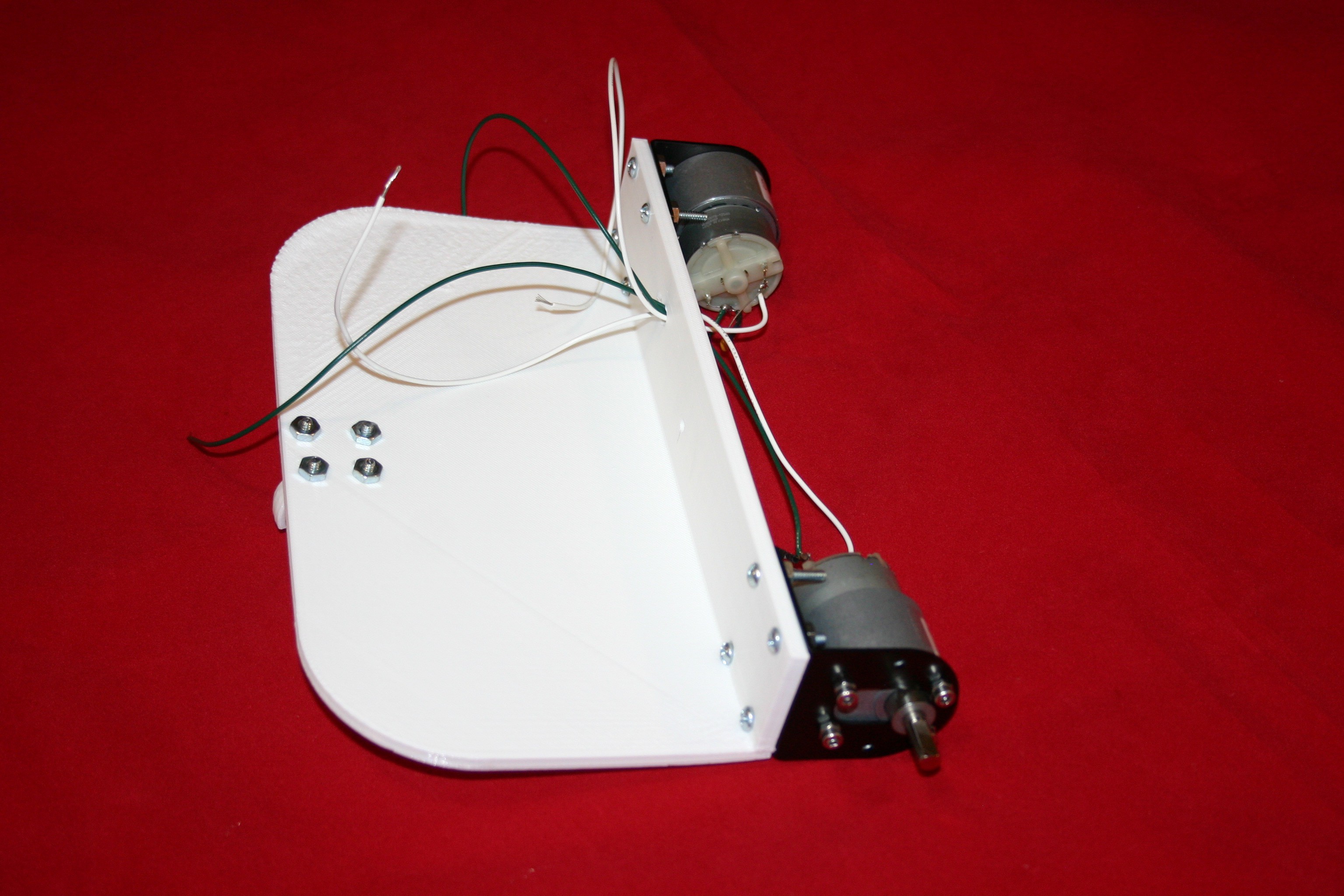
Drill holes and attach the caster wheel to the wide body (yes, I should have printed the holes, but it’s hard to preplan everything).
Attach the motors to the wide base (#6 x ½ nuts and bolts).
Attach the eye/nose assembly to the wide base.
Stretch the Eureka vacuum belts over the printed wheels.
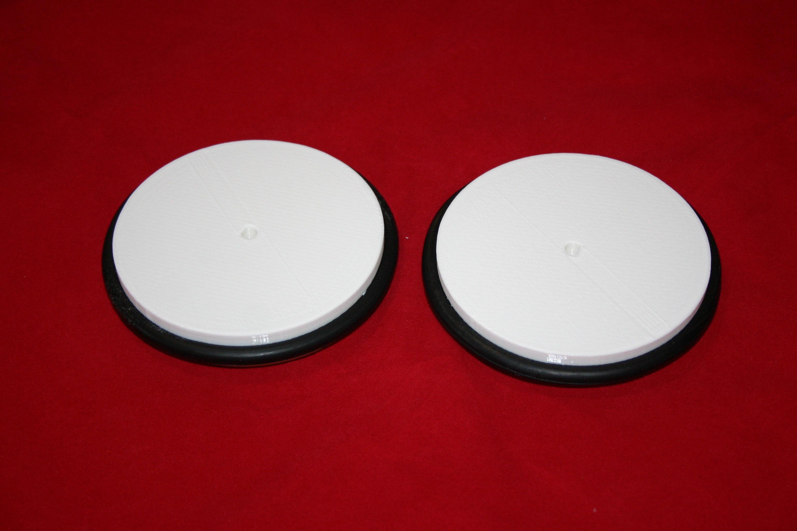
Insert (friction fit) the wheels onto the motor shaft.
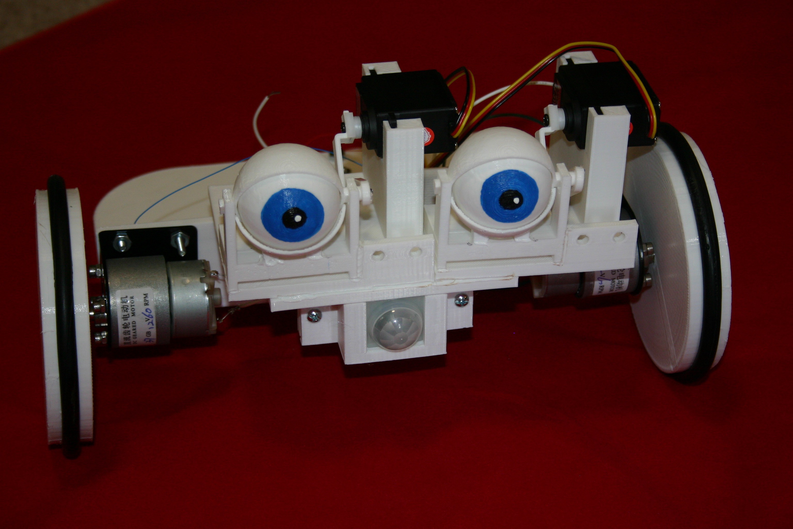
Paint the center of the eyeballs.
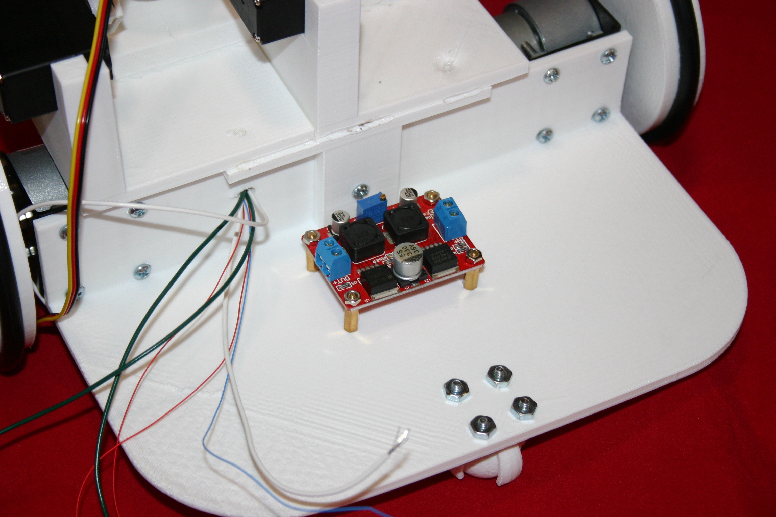
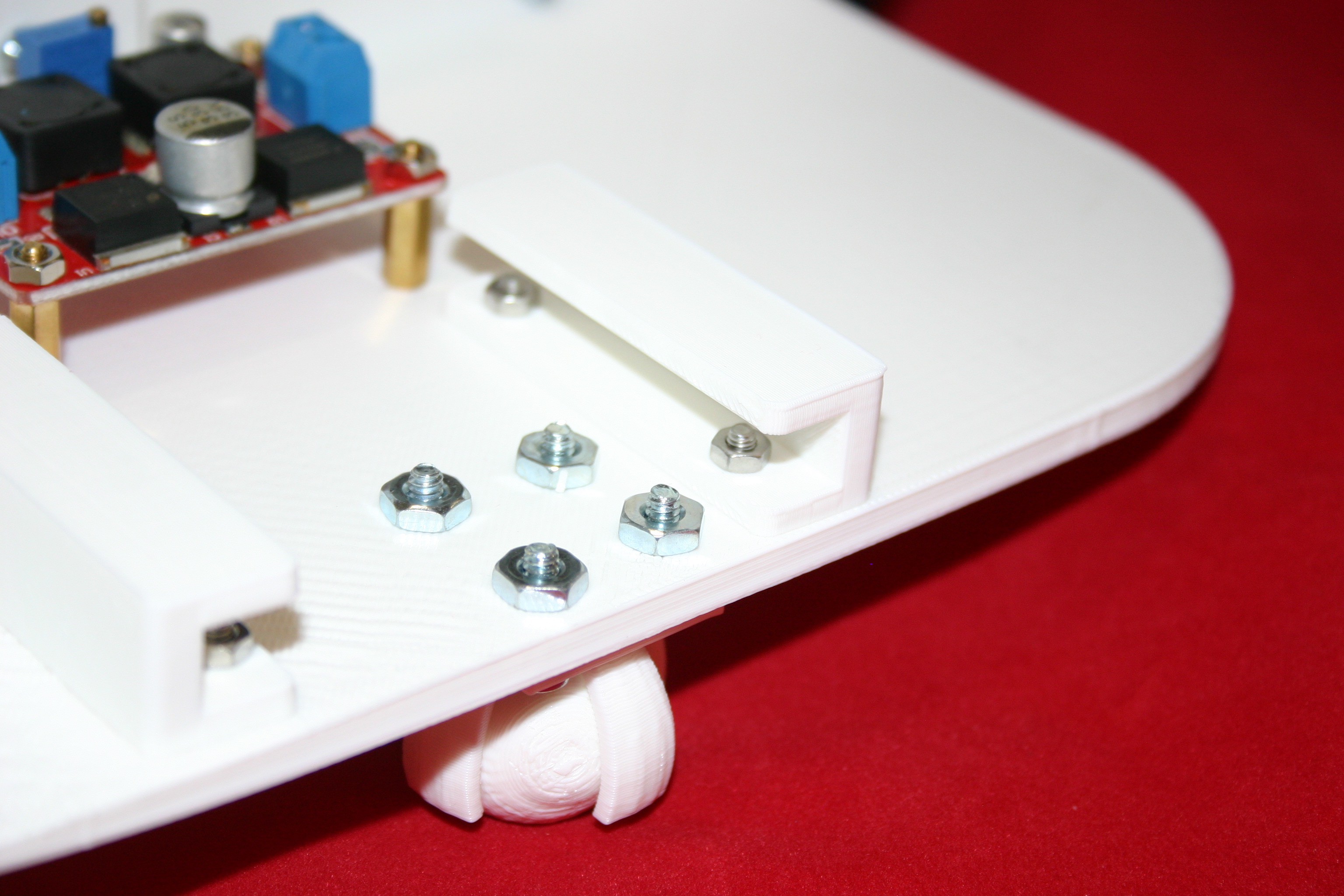
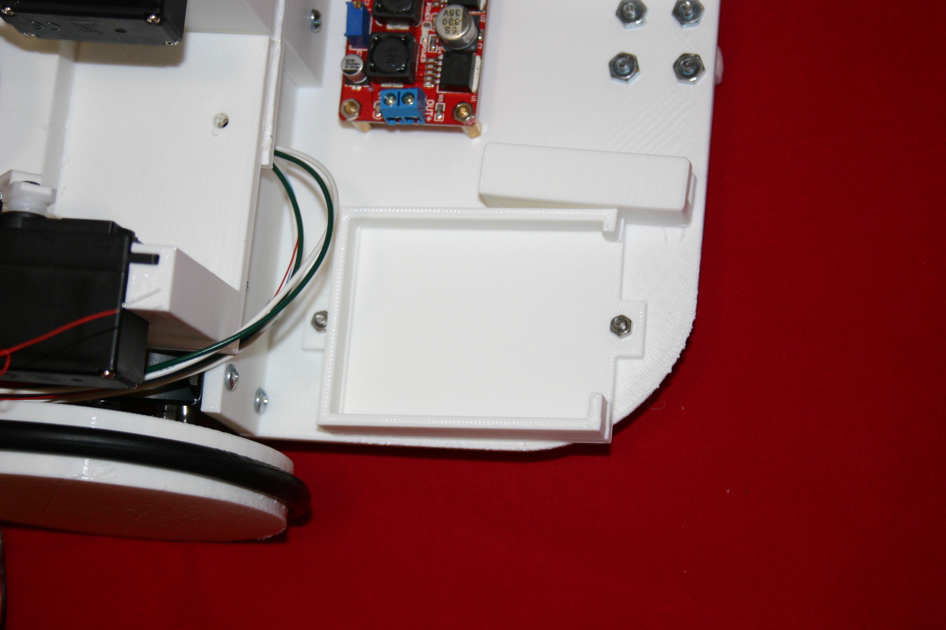
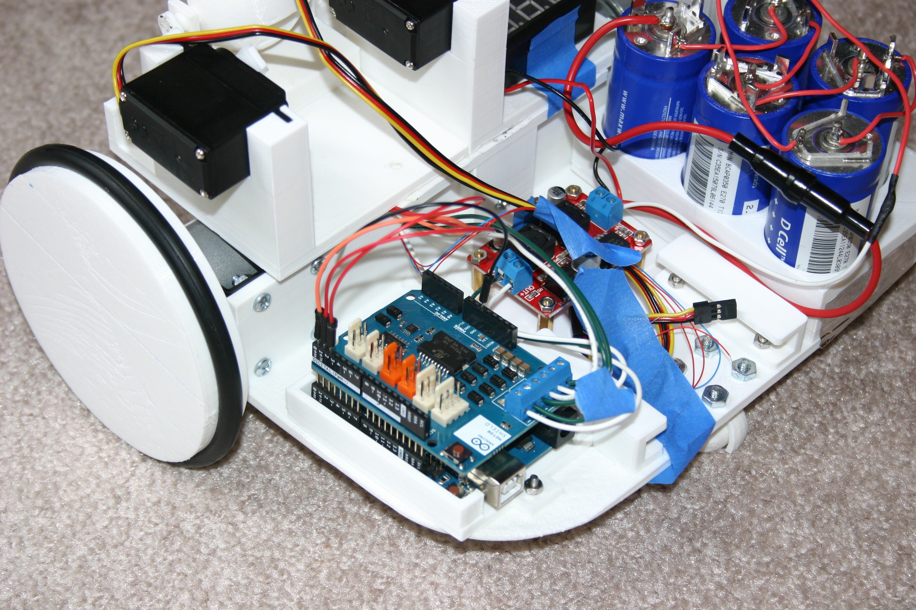
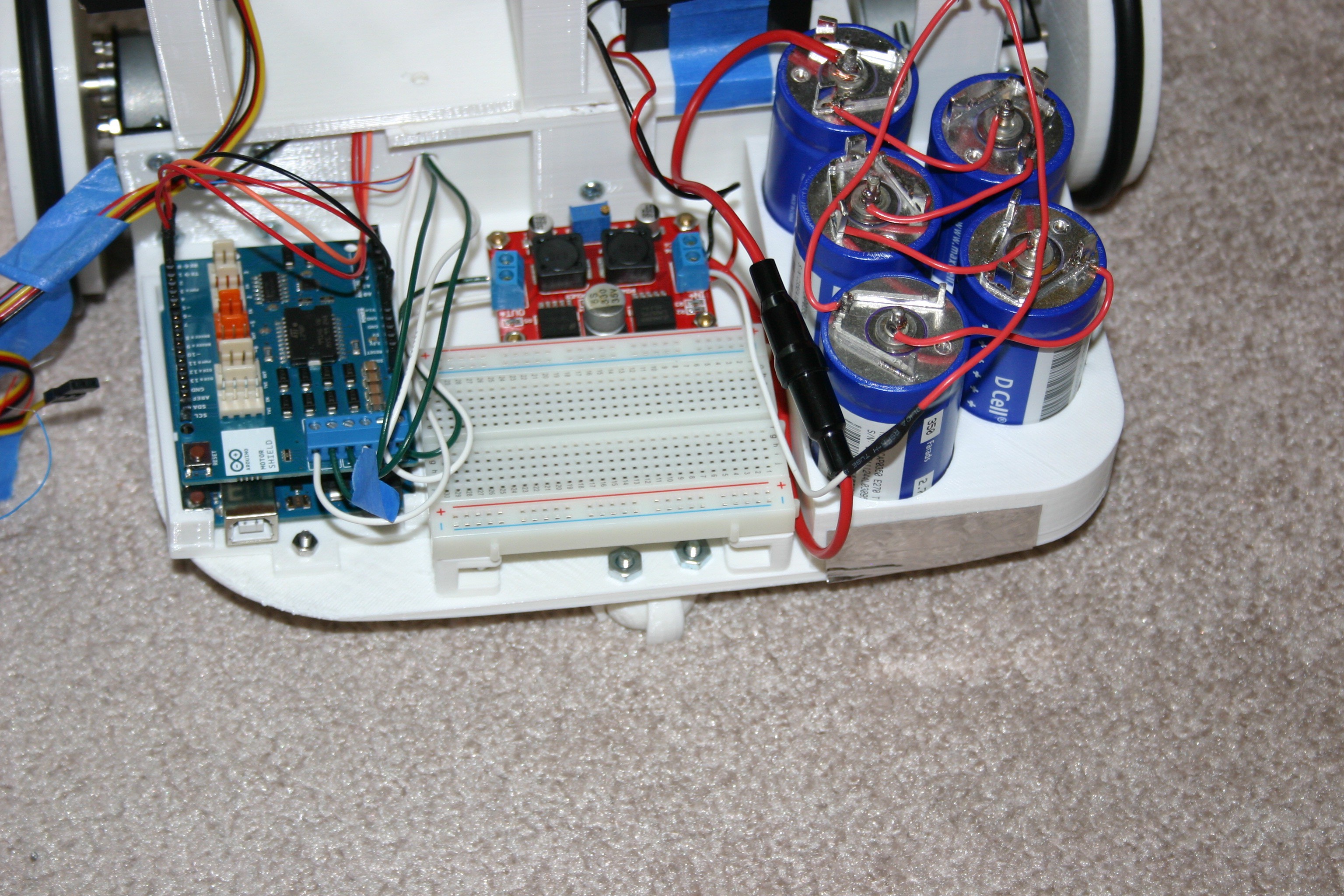
Install the DC buck/boost converter. Drill (2) 1/8 inch holes and use m3 x 12 screws.
Install the breadboard holders using m3 x 12 screws and nuts.
Install Arduino holder using m3 x 6 screws and nuts.
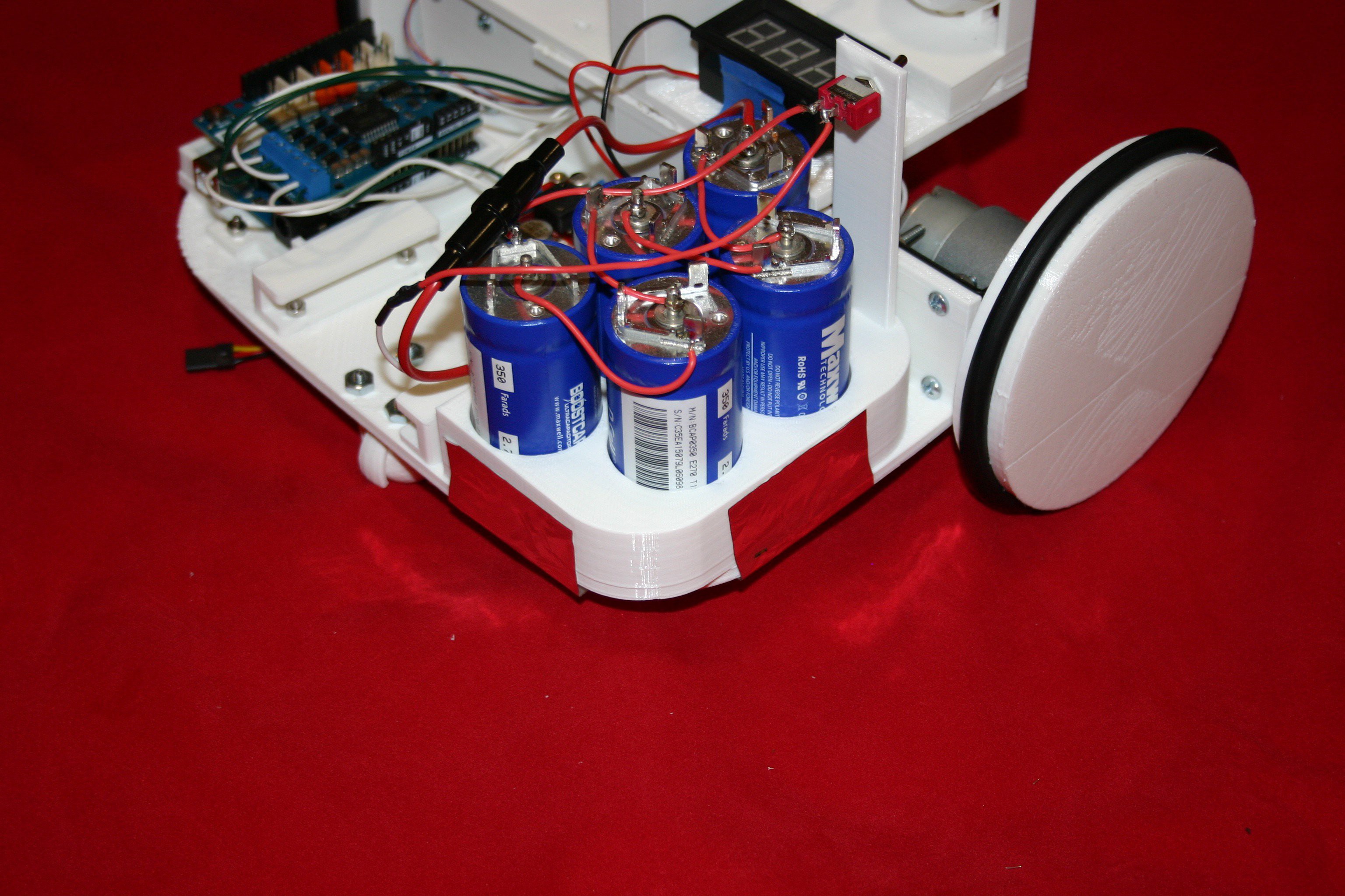
Solder capacitors together in series (using 100 watt or higher soldering iron). Add fuse on negative side and switch on positive end.
Connect motor wires to Arduino motor shield. Connect input power on motor shield to output of voltage converter.
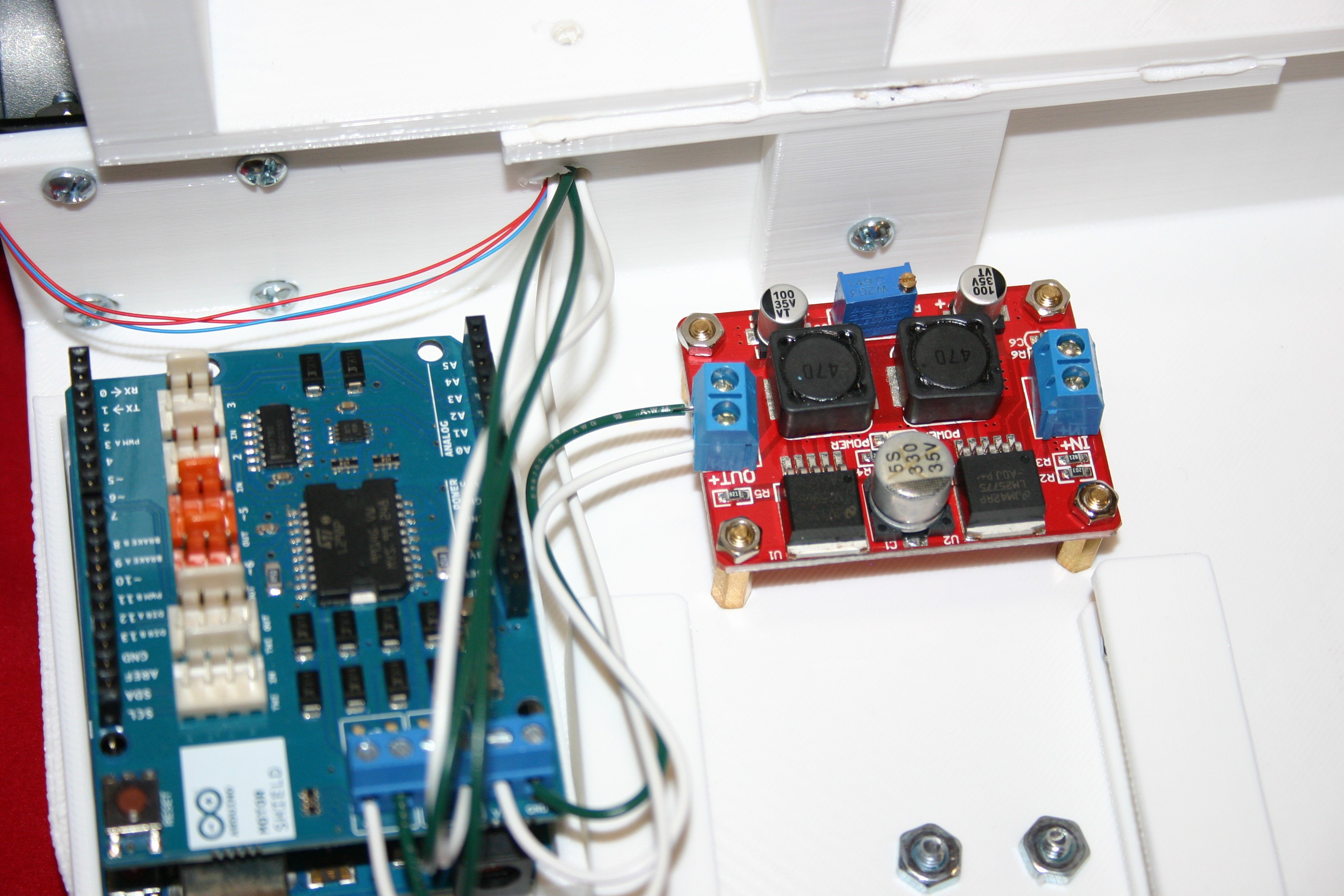
Connect capacitors and voltmeter to input of voltage converter board.
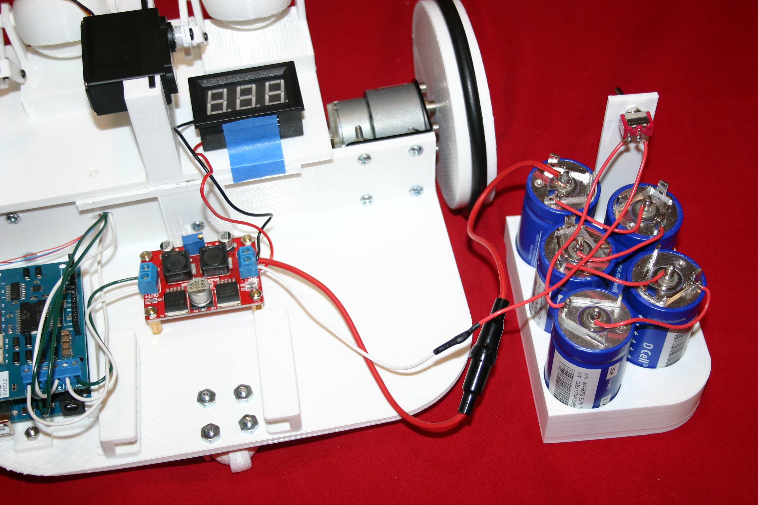
Secure capacitor assembly to wide base using duct tape.
Using wire wrap wire, connect three groups of (4) leds—each group in parallel with a series resistor. The upper slanting 4, the middle “line” 4, and the lower slanting 4 are the groups.
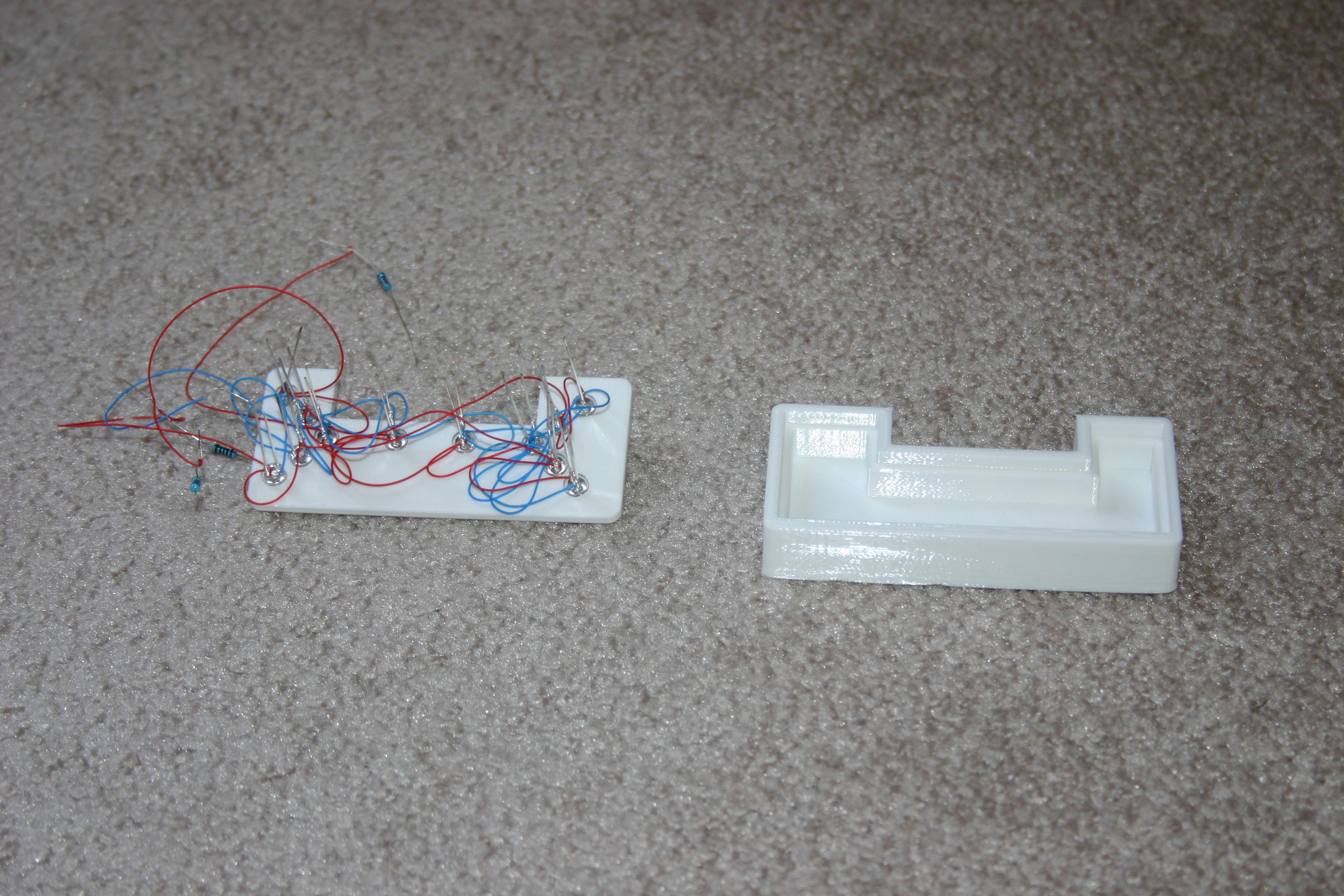
Test the lights before gluing the case together.

Thread the wires over the top of the wide base into the Arduino area.

Glue or melt the “mouth” to the nose.
Install the wires to Arduino pins 0,1,2 and gnd.
Remove the sticky backing and put the breadboard in place.
Install (glue) bump guard onto mouth assembly.
Install transistor switch to control power to servo motors. These motors consume about 60 milliamps just staying in place—and that is too much drain on our limited supply.

Check the wiring according to this schematic.

The Arduino file, “Little friend smile” is posted on hackaday.io
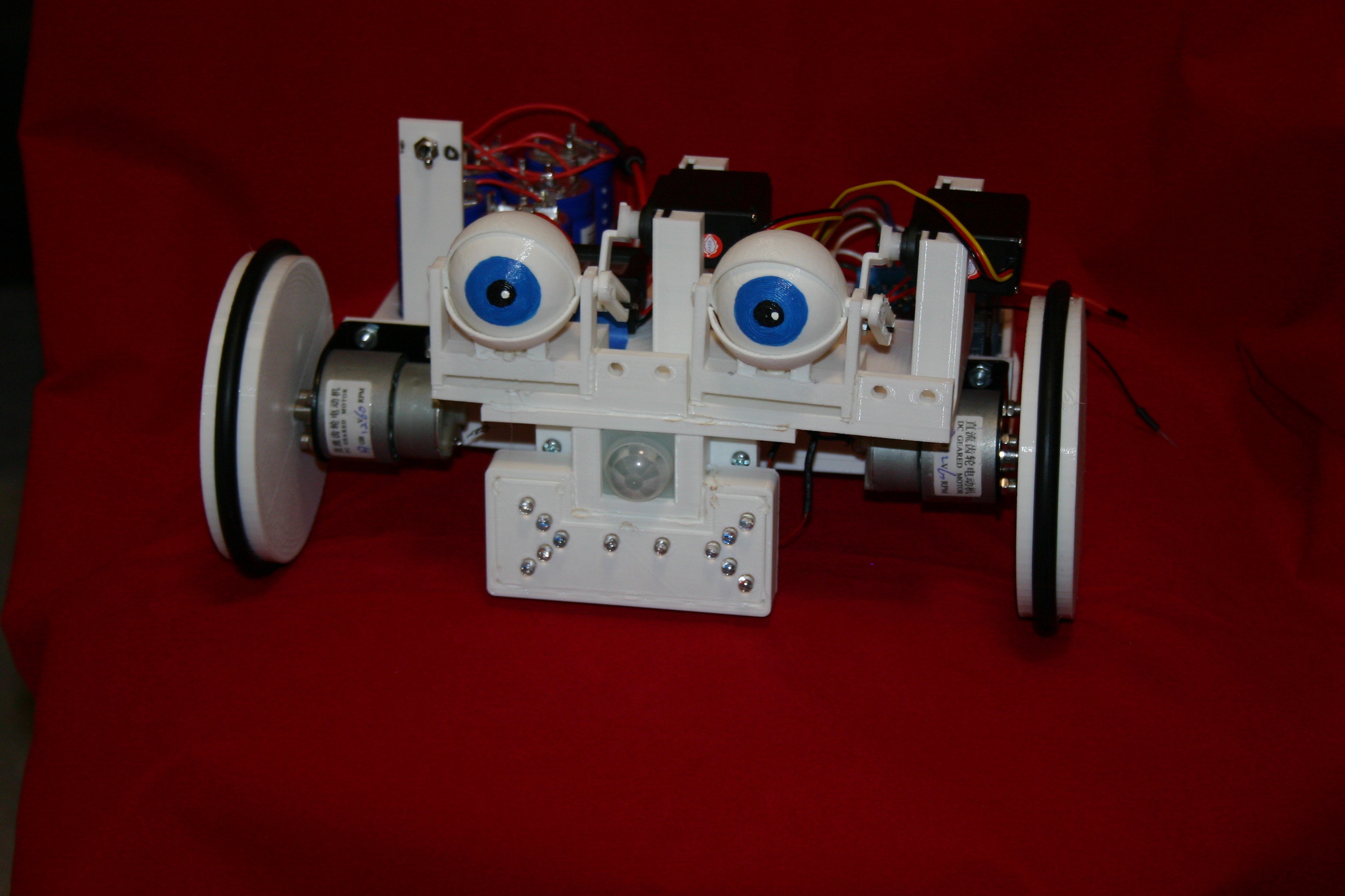
Mato should run with a smile on her face that turns to a frown when she bumps into something. Occasionally, she will blink.If it has been a while since a “bump” occurs, she will half close her eyes for a few seconds of rest. If someone walks past (PIR active), she will smile, wink and move forward.
Mato will run until the capacitor voltage reaches about 3.5 volts, but I usually stop for a recharge at 4 volts. Using a bench power supply, set the voltage for 12.8 volts and the amps for 4.5 (my supply is only good for 5 amps—more amps would charge faster).

Discussions
Become a Hackaday.io Member
Create an account to leave a comment. Already have an account? Log In.