 Sergei V. Bogdanov
We make some simple model to test the math.
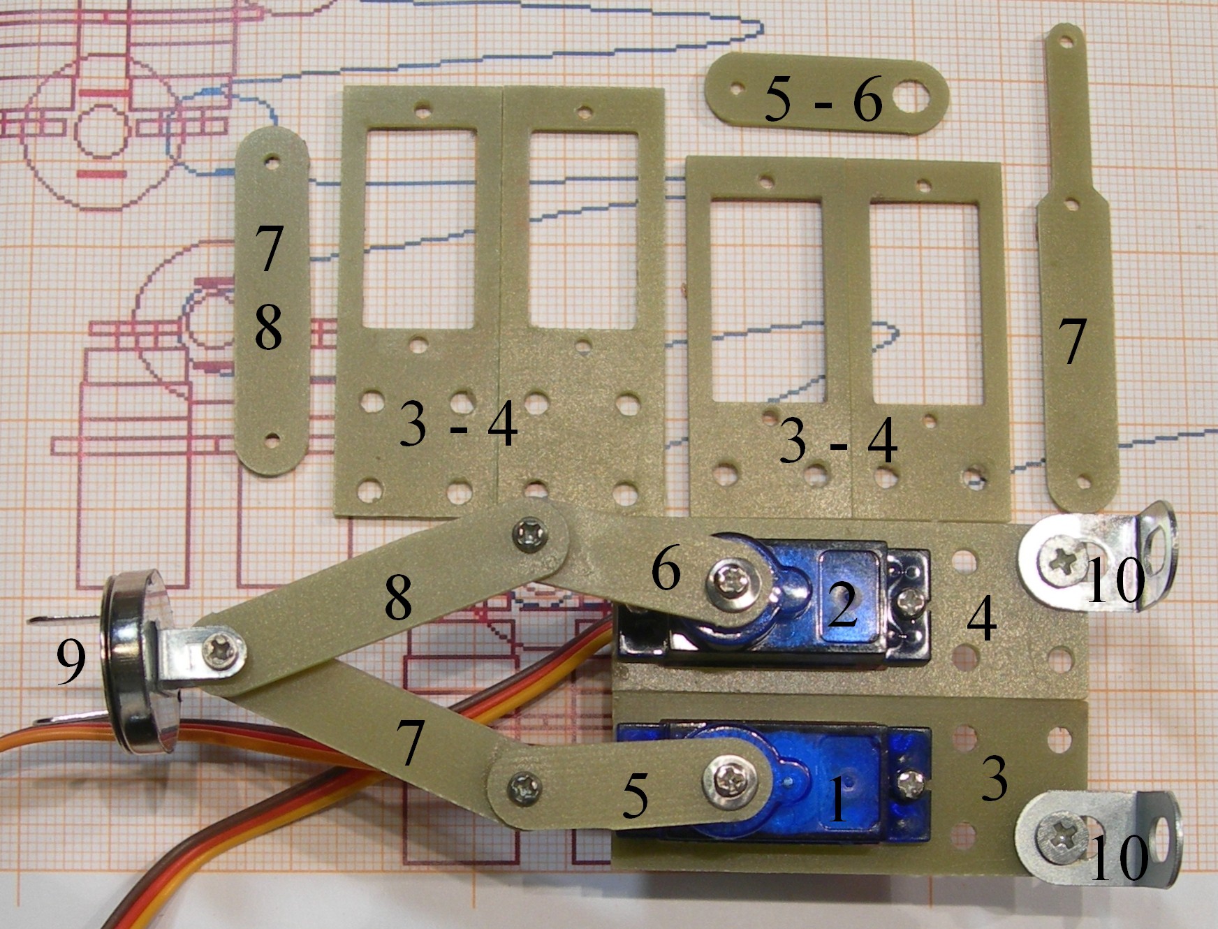
1, 2 – Servo S9G
3,4 – Servo brackets
5,6 – Low levers of FLM
7,8 – Upper levers of FLM
9 - Central hinge with pusher.
10,11 – Servo brackets holders
And the example of upper lever with Q=20, number 7 right up.
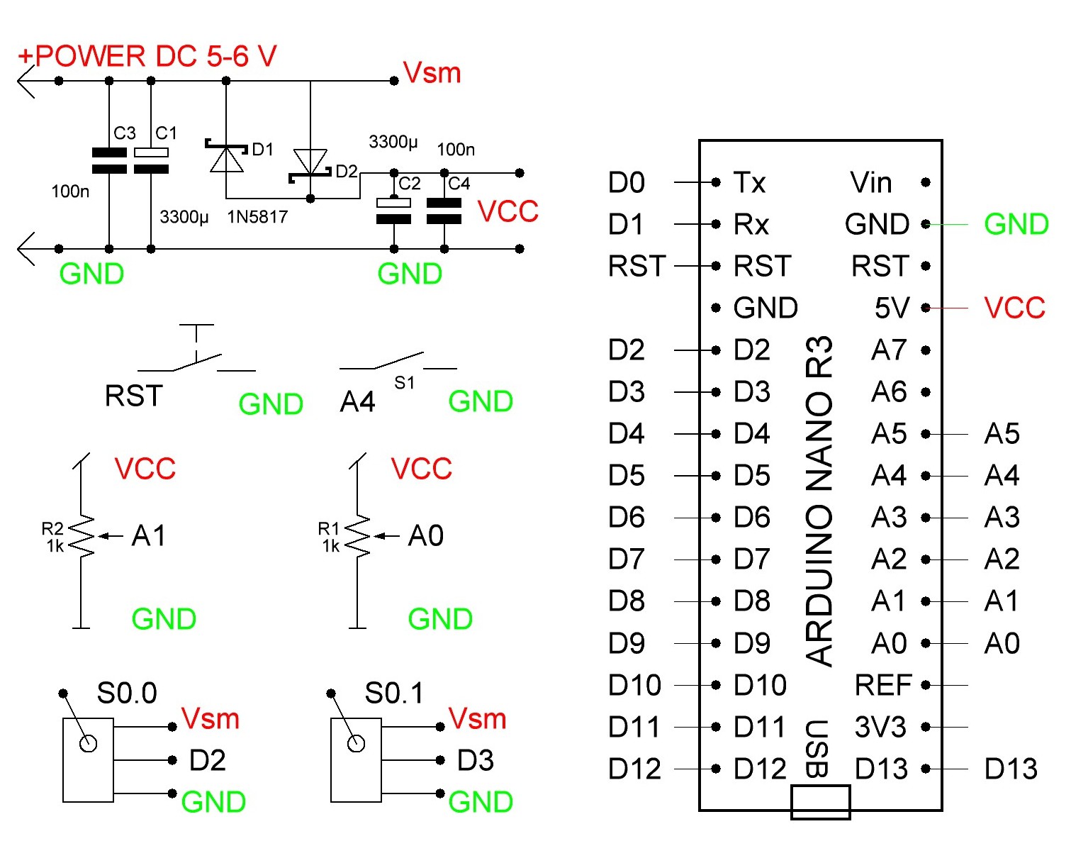
And the schematics for two servo and two potentiometers. See the program code for Arduino in "files".
Discussions
Become a Hackaday.io Member
Create an account to leave a comment. Already have an account? Log In.