 Chris
ChrisWhile a simple clock drive can track an object once it has been sighted, it is not capable of performing a GoTo to a object, so while it would be an option I'd like to be available in a complete system, I am not wanting to include it in this portion of the design.
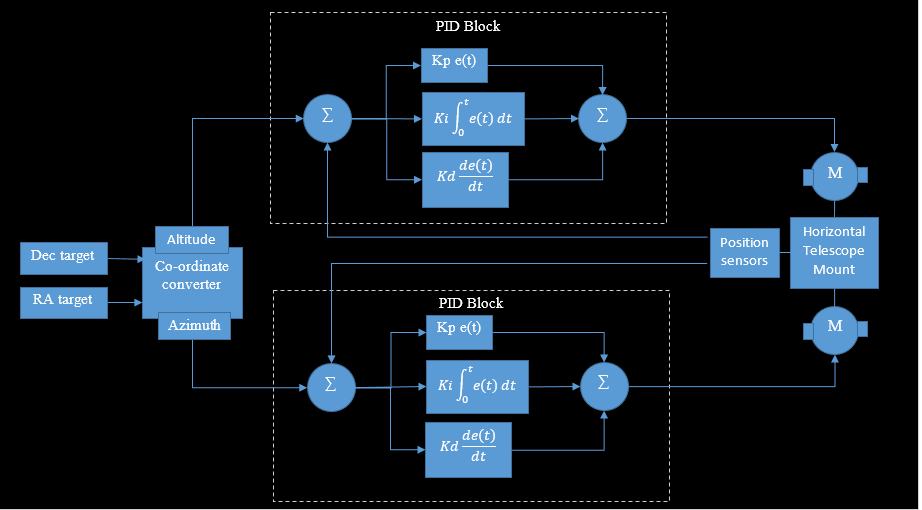
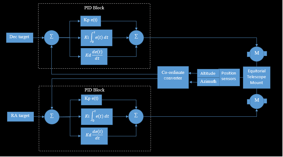
Of the existing projects for Telescope tracking, I've found that most of the control schemes use an open loop system of calibrating on one or more existing reference points, then counting steps of a stepper motor to give the desired position. This is susceptible to errors from mechanical components and some systems do allow you to compensate for backlash and such, but this requires a level of knowledge from the user to be able to do so. I'd like to close the loop and try to provide a system that is simple to set up and use. To do this I'm wanting to use a DC motor and use the sensors as the feedback for a PID loop as follows:
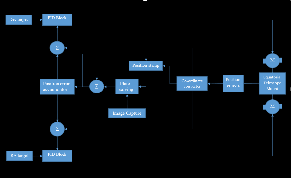
The latest image captured is tagged with the position and passed to the plate solving. The error between the position from the plate solving and the stamp is then used to correct the position from the sensors. Since I expect the plate solving to take a while and previous values of correction factor need to be included in the factor, it is fed into an accumulator before being used.
I'd like to figure out what instabilities this second correction factor has and if this can be dampened out, but I'm hoping that since the movements of the telescope are slow during tracking that they won't affect the picture quality.
Discussions
Become a Hackaday.io Member
Create an account to leave a comment. Already have an account? Log In.