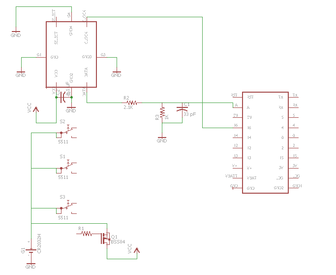
Getting started on the schematic. I'm using a microphone on a chip with a PDM output, fed through a low pass filter into the ESP's analog input with the ESP providing the clock signal. You'll also see a start on the circuit that provides the power supply, which can come in through either a hold signal supplied by the ESP or through the three input buttons. This way, the device will turn on when any button is pressed and will remain on as long as the ESP holds the signal low.
Too bad the microphone on a chip devices are only available in surface mount, and with weird pad arrangements at that. Some need circular pads or beveled pads - no SOICs or other convenient things that would be in EAGLE's library. A through hole one would make prototyping a bit easier. Well, that's what they make hot plates for, isn't it?
 dodgedart270
Discussions
Become a Hackaday.io Member
Create an account to leave a comment. Already have an account? Log In.