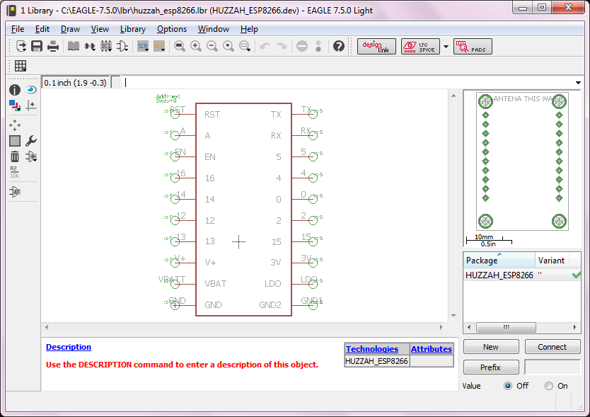
So, it's time to start the real design work. I use WinQCAD at work for PCB design, but it's no longer available, so I have decided to draw this one up in EAGLE. First order of business is to create a CAD file for the Huzzah ESP8266 breakout module footprint. Sure, there's probably a few out there, but making my own is a good exercise in learning the new software. I generally prefer to have my CAD symbols put the pins about where the real device has its pins, so I can better visualize how the routing will work while I draw the schematic. So my module symbol puts the pins in the same order as on the actual device.

In addition, I've created an MIT-licensed GitHub page to store CAD files that I might use across several projects and might be useful for others, so they are free to use by anyone (even commercial products) without worrying about GPL restrictions. The Huzzah footprint is the first file I've uploaded there.
 dodgedart270
Discussions
Become a Hackaday.io Member
Create an account to leave a comment. Already have an account? Log In.