Close
0%
0%

Wireless Navigation Sensor

A Wireless, Solar Powered GPS & Compass Dongle using Bluetooth Low Energy

Similar projects worth following
This will be a small solar powered device with GPS and an electronic compass, which can send its position over Bluetooth Low Energy (BLE).
Since it doesn't need external power, and uses Bluetooth radio to send its information it can be completely wireless and maintenance free.
It is originally intended for use on a sailboat.
It uses the standard Bluetooth Location and Navigation (LN) service.
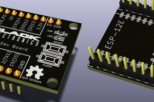
This is a spinoff from the PiChart project (https://hackaday.io/project/9471-pi-chart), building a chart plotter with a sunlight readable Pixel Qi display. It will use the nRF51822 Core Protoboard (https://hackaday.io/project/9967-nrf51822-core-protoboard)

Main components

  • NRF51822 based BLE microcontroller, €4.69
  • GPS module including accellerometer, €9.27
  • Electronic compass €4.03
  • 800 mAh Li Ion battery €4.48
  • Solar cell €1.27
  • Solar charging circuit: Undecided

Main BOM cost: €23.74

Power Budget

GPS: 11 mA @ 3.3V = 36 mW

Compass: 500 nW

nRF BLE CPU & Radio: about 1 mA @ 3.3V when active: 3.3 mW.

Total when active: about 40 mW. An 800 mAh LiPo battery would power it for 74 active hours, or about 9 days of 8 hour use with no added power.

I have bought 0.6W solar cells. Even if they deliver a fraction of the rated power, it should be sufficient to keep the battery charged.

Communication

There is a standard Bluetooth Low Energy profile called "Location and Navigation" which we can use.
Core51822-Schematic.pdf

The schematic for the Core 51822 boards that are quite cheap on E-bay.

Adobe Portable Document Format - 70.11 kB - 03/20/2016 at 22:07

Preview

u-blox6_ReceiverDescrProtSpec_(GPS.G6-SW-10018)_Public.pdf

Manual for the chip on the GPS board.

Adobe Portable Document Format - 3.71 MB - 03/20/2016 at 21:27

Preview

  • 1 × NEO-6M GPS
  • 1 × nRF51822-Core Microcontroller and Blueotooth Radio
  • 1 × 800 mAh LiPo battery
  • 1 × GY-511 LSM303DLHC 3-axis electronic compass with accelerometer
  • 1 × 600 mW solar cell From E-Bay

  • Board assembled, Appears to Work (the woes of QFN soldering)

    Erland Lewin05/13/2016 at 19:55 0 comments

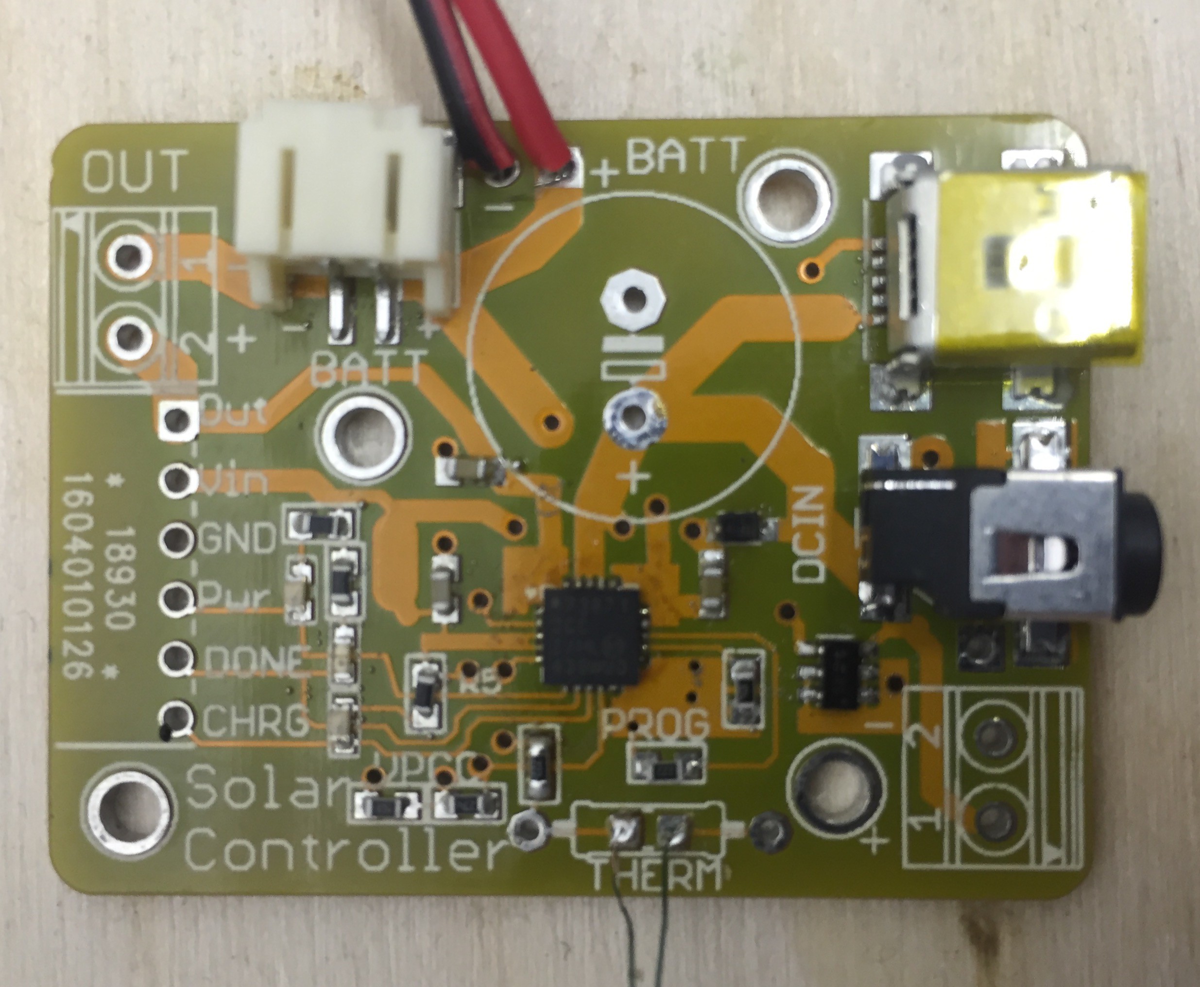
    I got the nice yellow PCBs for the solar charger board from OSHPark, and soldered a board (on a hot plate).

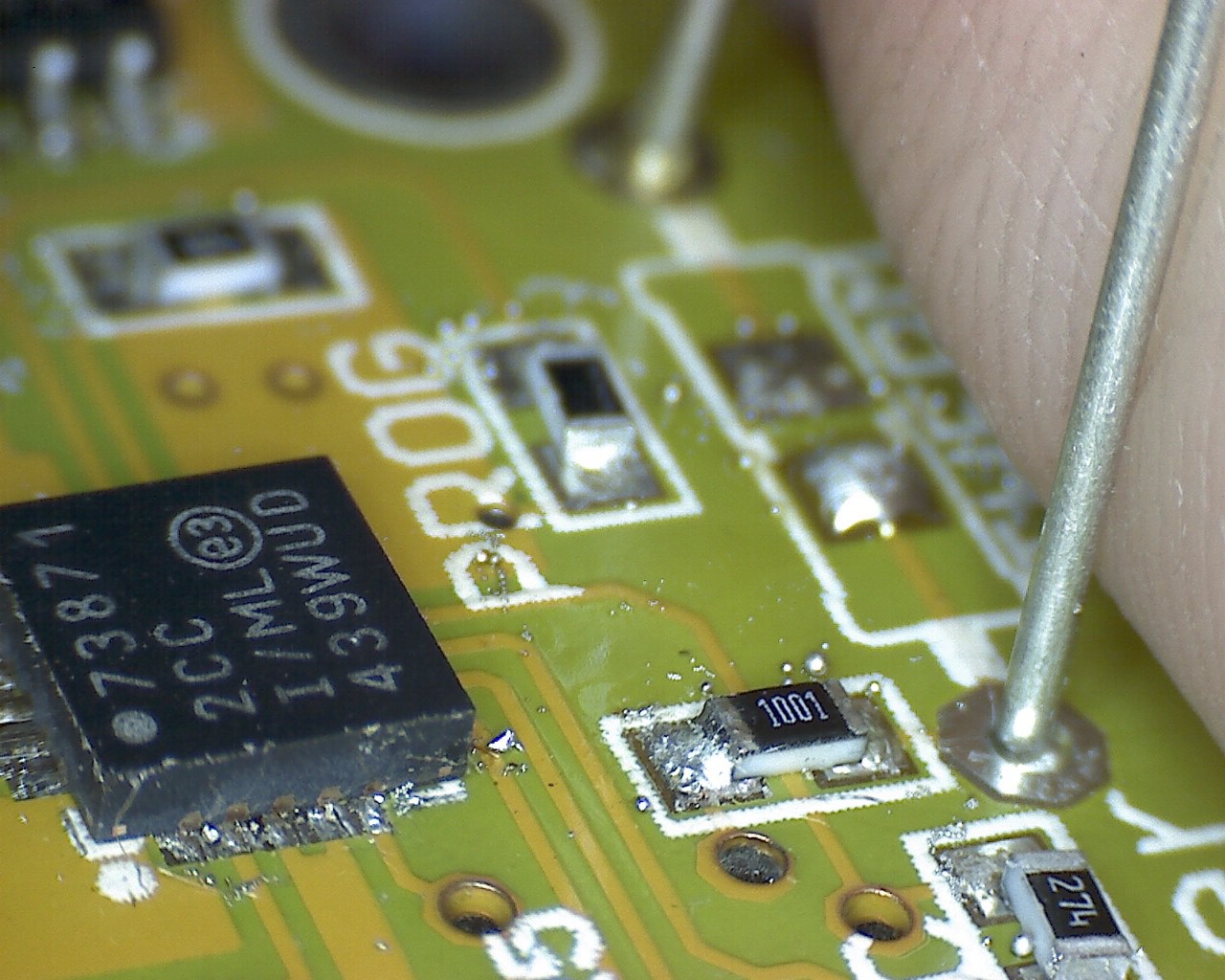
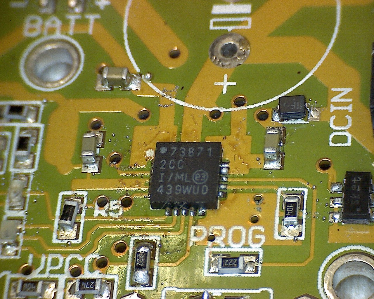
    The MCP73871 chip was really hard to solder. It is a 20 lead QFN, 4 x 4 mm with 0.25 mm wide pads on the bottom of the chip and a big ground pad in the center.

    For my first attempt, I mixed some lead free solder paste with flux, and applied it to the pads on the board using a simple USB microscope to see. I then placed the chip on the board, and reflow-soldered it on a hotplate. Then I mounted the rest of the components, reflow-soldered it again, and tested it. It did not work properly. I suspect the soldering of the QFN chip. I tried touching it up with a soldering iron, but without success.

    Today I made a second board. I cleaned the footprint with Isopropyl Alcohol (IPA), the applied solder paste to the pads on the board. Then I heated the board so that the solder paste melted on the pads. While the solder was liquid I poked at it so that there were no bridges. Then I took the board off the hotplate and let it cool. I had previously tried putting solder on the pads with a soldering iron, but I could not put solder on the exposed ground pad without creating a 'tip' where I removed the iron. I feared that this difference in height might ruin things.

    Then I put a dab of solder flux paste on the ground pad on the board, and carefully placed and aligned the QFN chip on the solidified solder on the pads. I used the USB microscope again to see that the alignment was good.

    Then I reflowed the board with the IC on it. When the solder melted, I again adjusted the position of the IC so that the pads were aligned (you can see a bit of the pads on the sides of the chip). Then I led the chip cool. Then I placed paste and the rest of components and reflowed the board.

    Now this second attempt works (the LEDs light up properly, and it seems like it is raising the battery voltage properly, and only works when the thermistor is connected, like it should).

    Here are two photos of the QFN chip through the USB microscope (an indispensable tool! I just bought it a week or so ago.). The resistors and capacitors are 0603-size (0.8 x 1.6 mm). The huge scary pinkish thing on the right side of the second photo is a part of my finger. The second photo is from my first, failed board. You can see that the pads are not perfectly aligned with the traces.

  • Solar Charge Controller board designed and ordered

    Erland Lewin03/31/2016 at 20:40 0 comments

    I realized the current limited DC/DC converted I had intended to connect the solar cells to wouldn't work well (the input voltage was too low, and it might pull the solar cell voltage too low for it to be efficient.

    What I really need is something like Adafruit's USB / DC / Solar Lithium Ion/Polymer charger - v2. The design notes for it are very interesting.

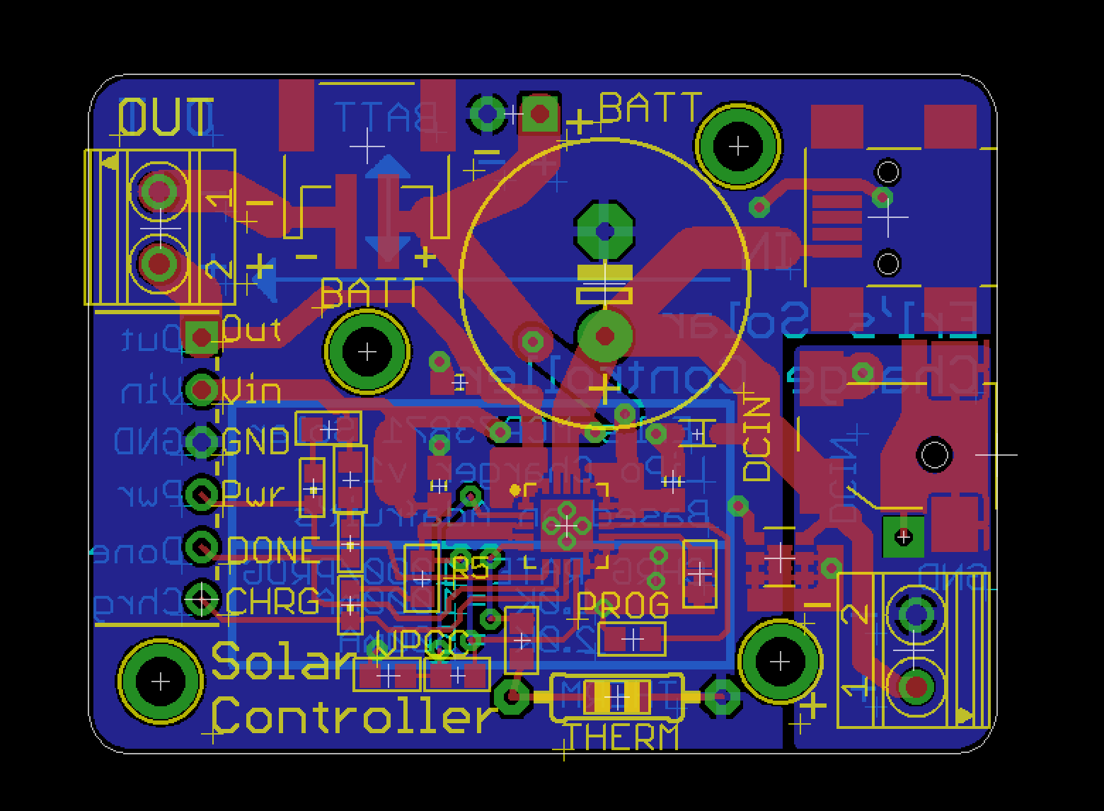
    However, the board seems to be out of stock at all English language sites in Europe, and not available on E-bay, so I decided to make my own version. It's available as a fork of Adafruit's GIthub project.

    I added a zener diode on the input to protect against overvoltage from the solar panel (over 7V fries the IC), changed the input voltage reversal protection diode to a Mosfet, changed the connectors a bit, and improved the routing.

    I ordered it today from Dirty PCBs (first try, before I've always used Seeed Fusion).

  • Source Code on GitHub

    Erland Lewin03/20/2016 at 21:24 0 comments

    I just pushed the code to GitHub. It probably needs some tweaking to build - don't hesitate to ask how to build it and I'll write some docs ;-)

    I use Nordic's SDK 10.0.0, and SoftDevice S110, using makefiles under OS X. See this log entry in the PiChart project about setting up the development environment.

View all 3 project logs

Enjoy this project?

Share

Discussions

Similar Projects

Does this project spark your interest?

Become a member to follow this project and never miss any updates