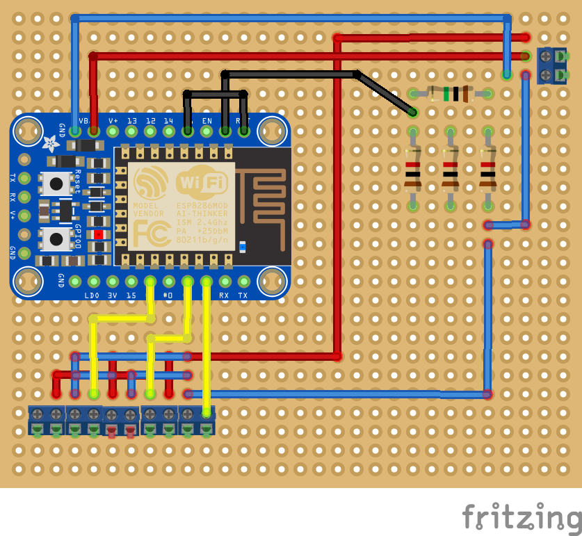
For those interested, here's a Fritzing approximating my build. It doesn't show all the back-of-the-board solder connections or the twin rows of headers for mounting the breakout board. It also shows 5x2pin screw terminal blocks for the DHT22s instead of the 3x3pin terminal blocks I really used.
The voltage divider upper right is wired in series on the underside of the board as is just about everything wired in parallel.

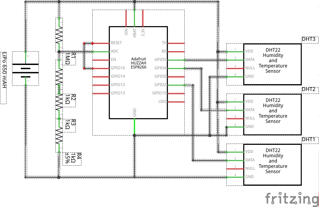
Here's a schematic showing how simple it really is. My Fritzing-fu is weak but I think it's readable.
- GPIO16 is jumpered to RESET to allow for sleeping
- The voltage divider limits the input to the ADC to a bit less than one volt
- The DTH22s are connected to battery power and ground. Next time I'll connecting them to 3.3V out on the breakout board
- DHT22 signal pins are connected to GPIO2, GPIO4, and GPIO5,
The code is the more interesting part of this but that's for a different log entry.

 Don R-Crenshaw
Discussions
Become a Hackaday.io Member
Create an account to leave a comment. Already have an account? Log In.