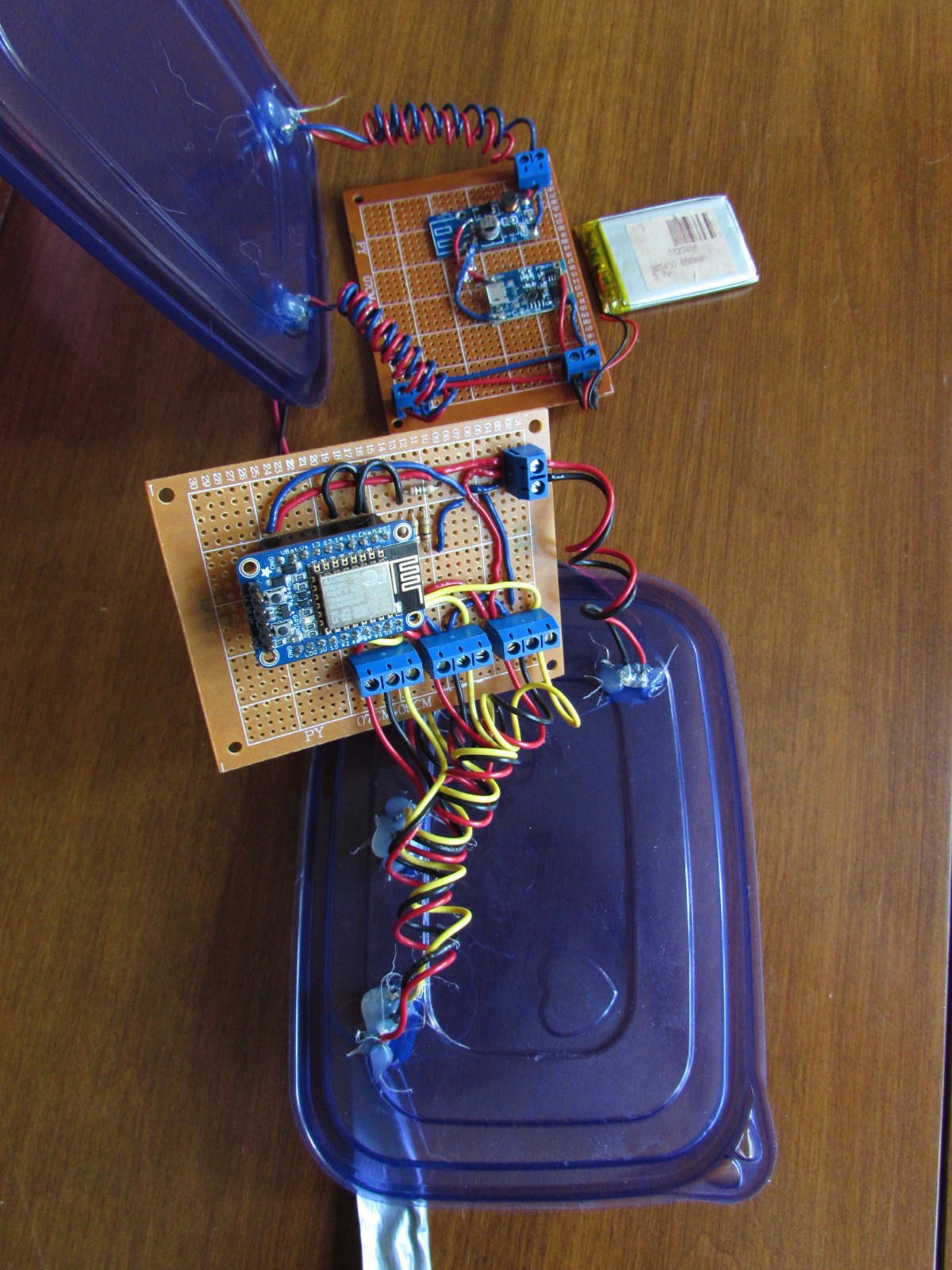
Lots to update. Let's start with the change of ESP8266 boards. It's relatively inexpensive ($10 US) and draws almost no power in deep sleep mode. In the image below, you can see it plugged into a couple rows of headers that are soldered to the relevant pins.
- VCC to the battery
- GND to the battery
- ADC though a voltage divider 1MR | 3kR
- Pin 16 jumpered to RST for sleep mode
- D2 D4 and D5 connected to signal from the three DHT22s
- DHT22 Power connected to battery (they only draw 50 nano Amps when sleeping).
Next iteration will connect them to 3.3V out on the ESP8266.
 Don R-Crenshaw
Discussions
Become a Hackaday.io Member
Create an account to leave a comment. Already have an account? Log In.