HV Joule Thief
A joule thief that can produce a high voltage output for powering neon bulbs
A joule thief that can produce a high voltage output for powering neon bulbs
To make the experience fit your profile, pick a username and tell us what interests you.
We found and based on your interests.
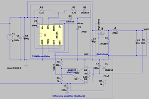
At this point I have built this circuit according to the schematic. It works well enough to drive single neon bulbs off a single AA cell, though I have only tested with 1.23V minimum as that is the lowest voltage that my crude bench supply can provide. For phosphor coated bulbs or with multiple bulbs connected it is usually necessary to increase the input to 1.5V or so.
When I increase the input voltage I get an increased HV output, which is nice. However, once I increase the input voltage high enough, the circuit will stop operating correctly and won't provide enough output voltage anymore. My goal right now is to understand why this happens and if possible, find a solution for this problem. It is nice that this circuit could run off a single cell battery, but I would like to be able to run it on better power sources if I want more output. I will try to get more information about this issue with my oscilloscope, and I will post an update with some scope captures.
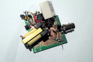
Here's how I built this circuit. If you wish to make your own, you may need to do things differently depending on what materials you have.
At this point you should be able to power up the circuit and check the voltage of the capacitor on the secondary. You could do this with a multimeter but I prefer to use an oscilloscope to get more information. If your circuit has no output or it is very low, the polarity of the secondary could be incorrect. Swap the ends of the coil around on your breadboard and try again. With my circuit I was getting an output of about 40V for 1.5V input. Interesting, but not enough to drive a neon bulb. There are a couple solutions to this. By tuning the circuit I was able to get the output closer to 70V, still not enough but a big improvement. I solved this issue by winding another coil of fine magnet wire on top of the secondary. This gives you two HV coils, which you can wire up in series to get higher output voltage. I recommend insulation between these two HV coils, such as the Corona Dope coating I mentioned before. With the two HV coils and proper tuning I was about to get up to 200V output using 2.8V input. I will describe the tuning process next.
Create an account to leave a comment. Already have an account? Log In.
You mean balanced AC? I rectify the secondary into a capacitor so it's fairly smooth, but it is DC. I'll post the schematic tonight
Yes, I mean balanced AC, so the same RMS current flows in both direction, which keeps the electrodes from deteriorating. This is why CCFL's electronic ballasts have a 2-transistor oscillator with a 3-windings transformer.
I must have a CCFL inverter somewhere with a single transistor but it uses a 3-windings transformer too, one for low-voltage power input, the other for high voltage ouput (many thin wires) and a 3rd for voltage sense.
How many BJT did I kill with bad design of my "experimental Joule thieves" ? :-)
Interesting. I never knew that. I wonder if that's what limits the lifetime of nixie tubes?
Maybe. I was thinking about them while writing. However they work at lower power levels and their electrodes are probably different. Neon bulbs however are meant for AC.
Nixie tubes are essentially neon lamps. In a neon lamp only the negative electrode lights up. This is what you want for a nixie. If you drive a neon lamp with AC, both electrodes light up (alternating). You do not want this in a nixie tube, so you can not drive it with AC.
Most sensitive to DC drive are fluorescent tubes with oxide coated electrodes, which can sputter away. But there are small hand held 8W fluorescent tube working lights with a DC drive voltage doubler circuit and often no electrode preheating. Yes they have lower lifetime than AC drive, but they work for relatively long time. It is less than ideal, but CHEAP.
If you have a CCFL in a display, it is not replaceable. So you really want the longest possible lifetime and drive it with high frequency AC.
BTW You might have seen my project: https://hackaday.io/project/2138-discrete-inverter-for-led
I bumped up the efficiency by using a BJT/MOSFET hybrid to increase the efficiency and also implement a voltage feedback.
LEDs are polarized elements so the issue of AC is not present there.
But yeah, nice circuit :-)
I have designs for driving VFD filament, but it is in the pipeline. The new design uses a single ended driver, but more or less balanced AC due to the resonant design.
Cool project! I've seen some hybrid circuits before but I've never built one.
Become a member to follow this project and never miss any updates

 Vedran

 Jenny List
 Burkhard Kainka
Hi ! Just a little note : HV lights like neon bulbs require alternating, balanced voltage to prevent electromigration and breakdown of the electrodes. However the typical Joule thief is unbalanced so it's not suitable for long term use...
But yeah, I love the Joule thief too ;-)