Christoph
-
"Divide and Conquer"ing seems to work, sort of
06/19/2014 at 22:38 • 0 commentsThis is a follow-up to an earlier project log. I decided to divide the celestial sphere into 1280 patches (20*4³) instead of the 2880 I chose to use earlier, but that's not really important.
Important is that this actually works as intended. My goal was to be able to have a center patch whose centroid is closest to the telescope's viewing direction and a list of the corresponding neighbour patches. The distance between the viewing direction and the centroid of a patch is the great-circle distance, and some hysteresis (1°) is introduced to avoid jumping back and forth near the boundary between two patches.
A patch manager class keeps track of all this and has an update method with the only argument being the current viewing direction. It calculates the distance between the center patch and the viewing direction and the distances between the neighbours and the viewing direction. If a neighbour's distance is smaller than the center's distance, this neighbour becomes the new center. This is repeated until no more improvement was made.
With the current patch size, traversing from the zenith to the horizon is done in 10 steps and takes about 100 ms (10 ms per step). That includes all the great-circle distance comparisons and reading from the SD card for fetching the next set of neighbours. This is surely fast enough for "normal" hand-operated usage.
-
Added the CC3000
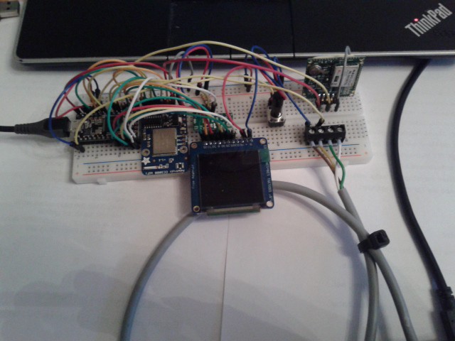
06/19/2014 at 16:57 • 0 commentsI added the CC3000 breakout board to my breadboard and ran the examples that come with the adafruit library. I powered it from 3.3V first and wondered why it didn't initialize, but it did after I gave it 5V. It's getting a bit crowded:
![]() The input device's screw terminals moved to the right, where the GPS is. The CC3000 board is between the display and the Teensy because I wanted to have the SPI devices close to the controller.
The input device's screw terminals moved to the right, where the GPS is. The CC3000 board is between the display and the Teensy because I wanted to have the SPI devices close to the controller.I'll now have to figure out how to mix all those different SPI drivers for the Display (my own DMA SPI driver), the SD card (SdFat) and WiFi (CC3000 driver). I expect that to be quite painful.
-
So let's connect this...somehow
06/18/2014 at 09:08 • 0 commentsYay! My CC3000 module arrived so I can start tinkering with it and think about ways to get this device into the net. In a meaningful way - that's probably the hardest part.
I could
- upload usage data (like location, target, how long a target was in view)
- download object catalogues
- download current ephemerides for solar system bodies
- update firmware (this would surely be a nightmare to debug)
- ...
- really, I need ideas.
-
Divide and conquer
06/14/2014 at 16:17 • 0 commentsUntil I have figured out what catalogues I want to include in my device's database, I can work on the representation of the celestial sphere as a number of patches. In a system with very limited memory and low CPU power (even though the mk20dx256 has lots more than the AVRs I worked with earlier), I need to partition the data.
Starting with an icosahedron, I will divide the sphere into a number of patches (triangles), from 20 upwards. Refining it by dividing each patch into 4 (or 9, that works as well) new triangles, I can get a larger number of smaller patches, and so on - resulting in 80, 320, ... - you get the idea.
What level of refinement is "right"? That is subject to the following considerations:
- I can/will have to handle more than one patch at a time.
- A center patch, which includes the coordinate that is pointed at by the telescope, can have a number of neighbours. A neighbour is one that shares at least one point (not a line) with the center patch, so the center patch will have 12 neighbours - I need to manage 13 patches.
- During panning, the telescope's view will eventually leave the center patch, and move into an already "loaded" (whatever that means, I don't know yet) neighbour. That will become the new center patch.
- That means that the center+neighbour patches should cover at least the displyed area of about 10° x 10°, a bit more won't hurt.
- The area covered by one triangle of an icosahedron is about 1/20th of the sphere's surface, and I need to display a spherical cap that is about 14° across (that's the display's diagonal).
And now it's time for some math. The surface ratio between a spherical cap and the whole sphere is
![]()
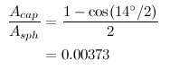
Putting in the display's diagonal yields
![]()
for h, so we get
![]()
which means that the device display 1/268th of the sky. This now must be divided by the number of patches we display at a time, which is 13. One patch must therefore cover 1/3484th of the sky - that's a lot of patches! A possible icosahedron refinement that gets close to this is 20x4x4x9 = 2880. I'll go for that.
If you find seríous errors in the above, please tell me!
Each patch will be stored in a file on the SD card. The information stored per patch is:
- the neighbour indices,
- the indices of objects that are in that patch,
- the patch center coordinate. I need that to tell if it's the center patch
-
Input device: Partially finished and connected, and I have a working menu
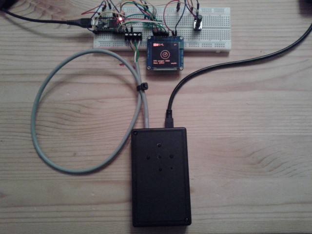
06/09/2014 at 10:12 • 0 commentsI finished the input device's enclosure yesterday to get rid of the second breadboard. It doesn't have a touch wheel yet, but it happily reads buttons and send button press events to the main device. Here's a picture of both:
![]()
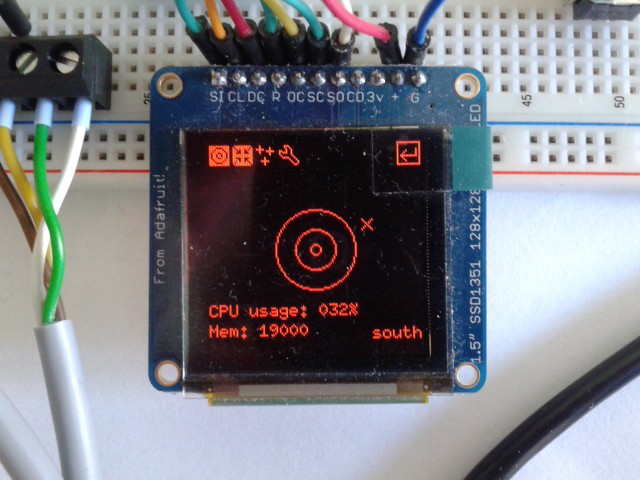
Both devices are still powered over USB until the input device gets a battery added. It will then supply both, and it will contain a charger circuit. I'll add a good pair of connectors so that it can be detached from the main device for charging. Here's a closeup of the display:
![]() In the above picture, the display is showing some icons along the top edge. It is an overlay that can be shown by pressing the center button. The two leftmost icons activate the telrad circles and the target marker. The rightmost icon has a frame drawn around it to indicate that it has focus. It is the "return" button that would close the menu again, and the other two icons are not yet functional (they will be used for the nearby objects display and a settings screen).
In the above picture, the display is showing some icons along the top edge. It is an overlay that can be shown by pressing the center button. The two leftmost icons activate the telrad circles and the target marker. The rightmost icon has a frame drawn around it to indicate that it has focus. It is the "return" button that would close the menu again, and the other two icons are not yet functional (they will be used for the nearby objects display and a settings screen).CPU and memory usage will of course disappear from the main screen later.
-
Object Databases
06/03/2014 at 00:03 • 0 commentsI started to create a kind of object database for the explorad. The first kind are the Messier Objects. Why those? When Charles Messier started to look out for deep sky objects, he didn't have the technology we have now, so the set of objects he listed is quite short (112 items). This amount is quite easy to handle, but it's enough to demonstrate that the object database will be quite complex and large for such a simple system like the Teensy 3.1.
I used the table from this site to generate a text file with raw messier object data, parsed that with a simple C++ program I quickly hacked together and saved the result on the SD card that sits behind the OLED display. Each Messier Object is 19 bytes long. That doesn't sound like a lot, but the overall amount of data for those 112 objects is 2128 bytes already. And that's just a tiny amount of what we can see up there!
Anyway, the explorad now knows about the Messier Object's
- number,
- "proxy" name (used for links to other catalogues like the NGC and WNC),
- parent constellation (don't know if I'm going to use that...),
- type (might be useful for filtering displayed objects),
- coordinates (right ascension and declination)
- and magnitude (also a candidate for filtering).
I'll now figure out and implement a system that allows me to populate a list of objects that will actually be shown in the explorad's display. This list will most probably be far too big for the amount of RAM I have left, so there must be some kind of tiling, dynamic loading and unloading of tiles, filtering, and so on.
Also, more object types should be included. Solar system bodies (planets and such) are definitely a candidate for this. Or the International Space Station. Unfortunately, the coordinates of the planets around us are far more dynamic than those of e.g. the Andromedy galaxy. That's going to be interesting.
-
Split breadboards into main and input device
05/31/2014 at 13:14 • 0 commentsThe buttons were moved to an external input device (currently breadboarded), which now sits next to the main breadboard:
![]() The Teensy 3.1's inputs are 5V tolerant, so I can safely connect the Teensy 2.0's Tx pin to the Teensy 3.1's Rx pin without additional hardware. However, I should add some protection before things blow up anyway. Fortunately, I still have a spare 3.1 somewhere.
The Teensy 3.1's inputs are 5V tolerant, so I can safely connect the Teensy 2.0's Tx pin to the Teensy 3.1's Rx pin without additional hardware. However, I should add some protection before things blow up anyway. Fortunately, I still have a spare 3.1 somewhere.The two devices are still powered individually until I finally decide which side will have the battery.
-
External input device
05/27/2014 at 17:52 • 0 commentsI decided to build an external input device to process the button inputs and (hopefully) a touch wheel. It acts as a standalone unit and might be useful for a number of different projects, so I moved it to its own project page.
It is based on a Teensy 2.0 AVR prototyping board and will be powered by the explorad (or the other way around, I'm not sure yet).
-
Accelerometer and Perspective Projection work
05/21/2014 at 19:15 • 0 commentsI can now read the accelerometer and convert the readings to pitch and roll. In terms of horizontal spherical coordinates, pitch is equivalent to altitude. Roll is important as well, but in another context: When the explorad is attached to a telescope, we don't know if it is tilted around its viewing axis. Measuring roll can thus be used to rotate the displayed objects and the target marker around the viewing axis to compensate roll.
I have not yet built the hardware for measuring the device's azimuth, so I simply attached a potentiometer to my Teensy. When I turn it, the mount driver turns the reading into a fictional azimuth for testing.
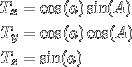
The projection of horizontal (azimuth, altitude) to cartesian (x,y,z) to display coordinates (x, y) is more or less straight forward. I use the Eigen library for matrix calculations, which might seem to be overkill, but it's convenient and I can do linear regression with it, which I might need later.
Here's a picture with the target being south (azimuth = 0) at the horizon (altitude = 0), with the device pointing slightly to the west (azimuth = 2.6°), below the horizon (-0.9°) and tilted counter-clockwise by 7.2°:
![]() The X mark shows where the target is and you can also see the three standard telrad circles with 0.5°, 2° and 4° diameter. The small square with circles in it at the upper left corner is a button I can use to toggle visibility of the telrad circles. The "dummy azimuth" potentiometer is right beside the buttons.
The X mark shows where the target is and you can also see the three standard telrad circles with 0.5°, 2° and 4° diameter. The small square with circles in it at the upper left corner is a button I can use to toggle visibility of the telrad circles. The "dummy azimuth" potentiometer is right beside the buttons.Next on the list: Add a GPS and suitable widgets for GPS/manual location and time input.
-
I just discovered mathurl
05/19/2014 at 14:20 • 1 commentneat.
![]()
Alternative with a white background:
![]()
More readable imho.
explorad
Work in progress: The explorad combines a microcontroller, a display, and star charts in a head-up display for astronomical telescopes.
 The input device's screw terminals moved to the right, where the GPS is. The CC3000 board is between the display and the Teensy because I wanted to have the SPI devices close to the controller.
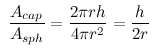

 In the above picture, the display is showing some icons along the top edge. It is an overlay that can be shown by pressing the center button. The two leftmost icons activate the telrad circles and the target marker. The rightmost icon has a frame drawn around it to indicate that it has focus. It is the "return" button that would close the menu again, and the other two icons are not yet functional (they will be used for the nearby objects display and a settings screen).
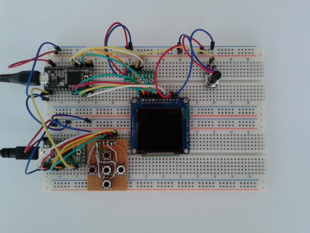 The Teensy 3.1's inputs are 5V tolerant, so I can safely connect the Teensy 2.0's Tx pin to the Teensy 3.1's Rx pin without additional hardware. However, I should add some protection before things blow up anyway. Fortunately, I still have a spare 3.1 somewhere.
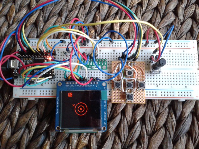 The X mark shows where the target is and you can also see the three standard telrad circles with 0.5°, 2° and 4° diameter. The small square with circles in it at the upper left corner is a button I can use to toggle visibility of the telrad circles. The "dummy azimuth" potentiometer is right beside the buttons.