 Alex Hunt
Although there has been radio silence for a few weeks, I have been working hard(ish) on the project. Today I designed my very first PCB, which is the sensor part of the project.
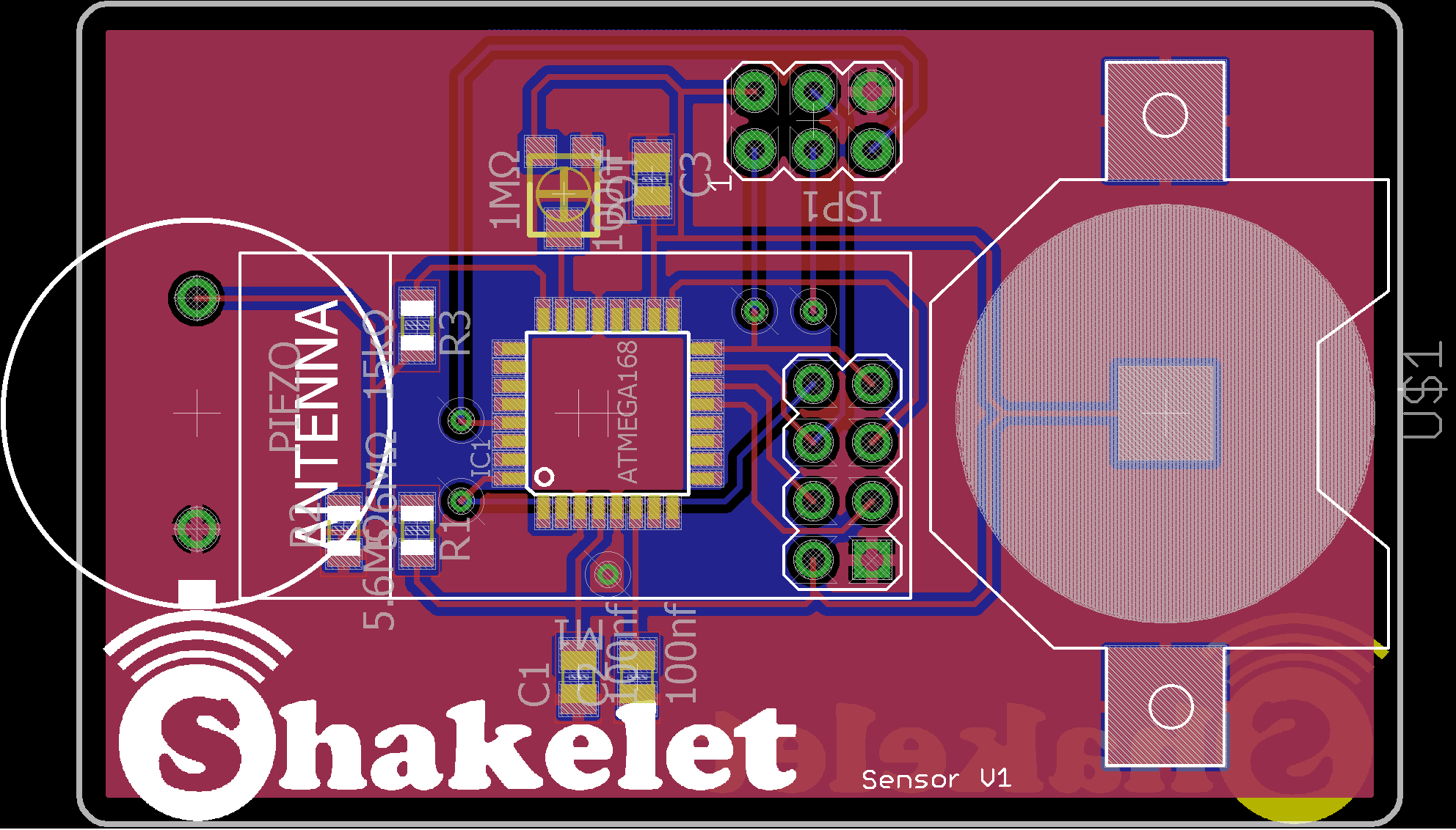
The full PCB file can be found in the documents section and I would love and feedback anybody would care to give! In particular, I'm slightly concerned that pin 6 isn't connected to ground, although Eagle did not throw up any errors.
One addition to the circuit is a potentiometer in the top right. I am using this to provide a threshold to the AVR to use for sensitivity adjustments. The code is now much improved and I will upload in the next couple of weeks.
Next step, the bracelet PCB!
Discussions
Become a Hackaday.io Member
Create an account to leave a comment. Already have an account? Log In.